Upload BOM & Gerber

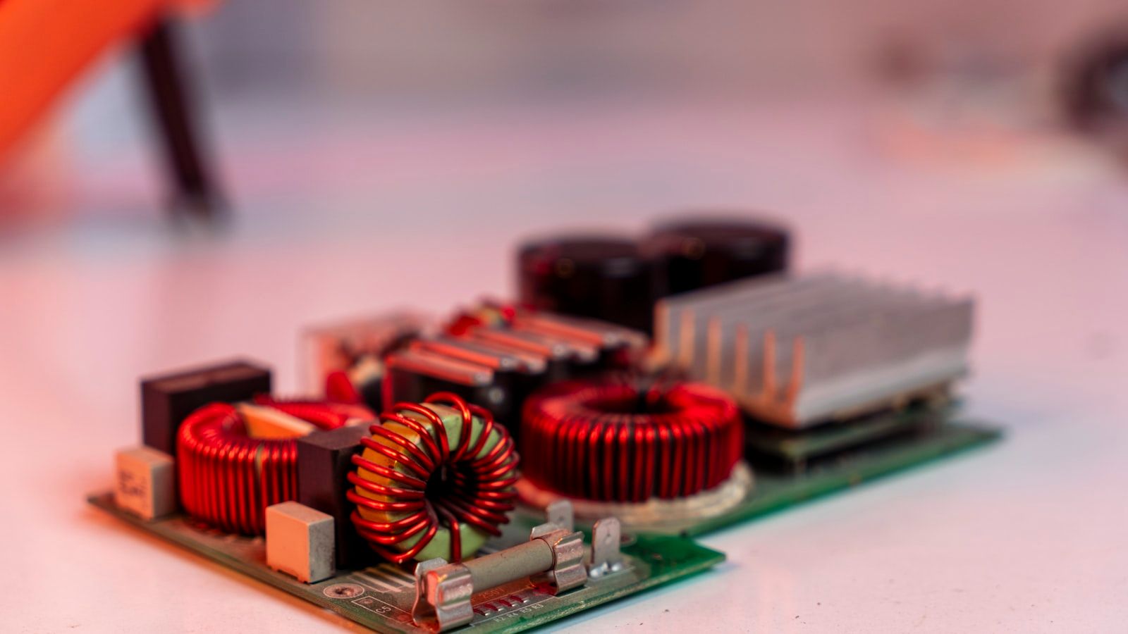
Industrial PCB fabrication is a controlled process for the manufacture of printed circuit boards and assemblies for industrial applications (e.g., automation controllers, electric motor drives, power conversion systems, measuring instruments, networking equipment, and infrastructure electronics). The term does not describe one fixed board type or one universal reliability class. The proper design, manufacturing processes, inspection methods, and validation documentation requirements for industrial PCB assemblies depend upon the product electrical load, operating environment, service life, failure consequences, and contractual acceptance requirements.
The final design, material system, fabrication data, component configuration, assembly process, firmware, test limits, deviations, and trace records must all match to define a single product state.
- Determine the operating conditions and failure risks prior to selecting the materials, copper, stack-up, coatings, and test severity levels.
- Look at DFM, manufacturing, assembly, inspection, programming, and product testing as linked process controls rather than as isolated activities.
Contents
show
What Is Industrial PCB Production?
Production of a PCB for Industrial Electronics involves the steps of design transfer, material preparation, board fabrication, assembly of electronic components, inspection, testing, and release controls. Products manufactured for industrial electronics can include only a bare PCB, an assembled PCBA, a programmed controller, a tested subassembly, or a completely integrated electronic unit. The production boundary must be clearly defined before the manufacturer can determine what records are required and which acceptance criteria will apply.
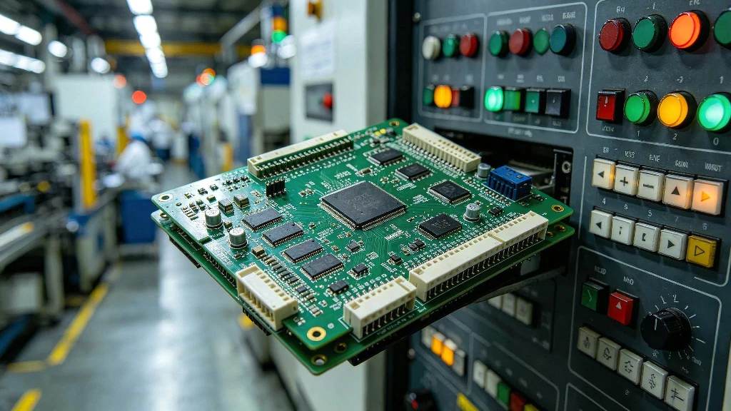
The term “Industrial” does not mean that the material has to be the most durable, use the thickest copper, be conformal coated, or meet IPC Class 3. IPC-6012F defines rigid printed circuit board performance classifications as being based on customer or end-use requirements. Deviations from the performance standard may be agreed between the user and supplier. Therefore, the practical issue for the customer is not whether a printed circuit board is labeled “Industrial,” but whether it has the construction and production controls to meet the application and its basis for acceptance.
By making this distinction, the customer avoids two extremes: 1) over-engineering a low-risk controller with costly materials or requirements for which there is no demonstrated reliability benefit; and 2) under-specifying a demanding product because a general capability table appears to meet the minimum specification. The operating conditions, critical characteristics, process capability, and acceptance evidence should be connected from the beginning.
What Makes Industrial PCB Production Different?
Industrial electronic products are typically required to operate for long periods of time while subjected to thermal loads, frequent switching of electrical power, mechanical stress, long cable interfaces, environmental exposure, or restricted maintenance. Engineering issues that affect Industrial Electronics products include signal integrity, mechanical stability, thermal management, and EMC.
A sealed sensor node, motor-drive controller, and laboratory instrument can all be industrial products while needing different material, spacing, thermal, and test controls. Fixed temperature ranges, product lifetimes, and copper weights should be treated as product-specific requirements, not definitions of the industrial category.
Materials and PCB Technologies for Industrial Equipment
When selecting materials and PCB architecture for an industrial product, the electrical, thermal, and mechanical requirements, as well as manufacturing requirements, should be considered. A useful basis of comparison is what problem the construction solves and what the supplier must demonstrate for that construction.
A High-Tg laminate should only be selected when there is an application requirement that includes the assembly profile, exposure to higher temperatures, or reliability analysis that warrants such a selection; therefore, Tg alone does not determine the temperature rating for field-installed boards. Heavy copper can improve current-carrying and heat-spreading capability, but it also alters other processes such as etching, spacing, plating, thermal balance, and assembly behavior. You must release the controlled construction, not the broad material family.
Industrial PCB Production Process
Stage 2 is the point in the process when using verbal flexibility poses the most downstream risk. If an “approved alternative” laminate or copper specification was included in the approval process but was only identified in an email thread and not in the released stackup note, it cannot be enforced if a different line or shift runs the job — there will be nothing in the controlled data identifying that it was an agreed-upon substitution, and therefore no one downstream will know.
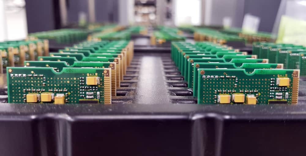
To see examples of how fabrication sequencing and production control interrelate, refer to the SUGA-PCBA bare-board manufacturing overview.
Design Considerations That Affect Industrial Production
High Current and Power
High-current or high-power switching devices, such as motor controllers, in close proximity to sensitive low-power control electronics create unique industrial design challenges. High-current paths must be designed based on allowable temperature rise, voltage drop, copper geometry, layer location, environmental conditions, and cooling assumptions. No arbitrary copper-weight standard can define a high-current path. High-power components, switching loops, connectors, and current return paths must be arranged so that they limit noise injection into low-power signals, such as analog sensing signals, and reduce unnecessary thermal coupling or noise in low-power circuits, such as timing circuits.
Heavier copper, copper inlays, large copper planes, and closely spaced vias change copper etching, solder-mask definition, lamination balance, drilling and plating requirements, and the heating required for reflow soldering. Therefore, supplier capability statements should be reviewed to verify that they match the actual conductor widths, copper thicknesses, spacing requirements, via structure, and panel construction used for the released design.
Thermal Management
Thermal design should follow the path from the junction through the package, PCB copper, vias, heat spreader or chassis, and finally to ambient air. You can improve heat spreading on your PCB by using additional copper, but the result depends on the geometry of the design. To study this further, TI compared two 3 × 3 inch, 2-layer PCBs that were identical except for the weight of the copper on the bottom layer. In the experiment, TI found that the thermal resistance from junction to ambient for the PCB with 1 oz of copper on the bottom layer measured 28.3°C/W, while it measured 21.2°C/W for the PCB with 2 oz of copper on the bottom layer. This demonstrates approximately a 25% reduction in thermal resistance under the stated test conditions. While this data supports improved copper spreading, it is not a blanket 25% rule for industrial PCBs.
In the TI application report, TI calculated a value of approximately 261°C/W for a typical 12 mil plated thermal via in one of the examples provided. By using a 4 × 4 array of 16 thermal vias under a 3.1 × 3.2 mm exposed pad, the parallel thermal resistance is reduced to approximately 16.3°C/W. Again, while this demonstrates improved thermal performance, the value stated here depends on the board thickness, hole geometry, plating, spacing between thermal vias, and connection to the copper layers. The production requirement is to control the actual via and copper geometry that created the validated thermal path.
EMI, EMC, and Signal Integrity
Industrial systems typically incorporate longer cable runs, switching power supplies, motors, relay contacts, high-speed interfaces, and sensitive measurement channels. Poor signal integrity in these environments can result in inaccurate or corrupted data, instability, and potentially complete system failure, while excessive emissions or susceptibility can create EMC failures. To produce PCBs reliably, one needs to implement a stackup and routing strategy that provides continuous return paths, separates noisy power structures from sensitive nodes, controls impedance where required, and incorporates filtering or shielding interfaces as part of the released design.
Production records must confirm the stackup, material, trace geometry, reference planes, connector configuration, and any controlled-impedance characteristics used by the validated design. An earlier hardware version passing EMC is weak evidence for the current design if any of the following has changed between designs: board supplier, stackup, cable interface, shielding arrangement, firmware behavior, or filter population.
High Voltage, Creepage, and Clearance
The required creepage and clearance for high voltage cannot be reduced to a single generic industrial value; instead, they depend on many factors including working voltage, insulation function, pollution degree, material group, altitude, transient conditions, coating or enclosure assumptions, and the applicable product safety standard for the equipment. Therefore, the design package should identify the governing requirement and the features within the design that implement it, while the fabrication drawing and inspection procedure for the PCB ensure that the stipulated creepage and clearance distances are maintained through manufacturing tolerances.
Mechanical and Environmental Protection
Reliability factors such as vibration, shock, heavy components, connector insertion forces, humidity, condensation, dust, and chemical exposure are influenced by component placement, board support, connector mechanics, mounting-hole strain, cleaning, coating, potting, and enclosure sealing. Therefore, the type of protection required for a given product design is determined based on its failure mechanisms. Conformal coating is one method of environmental protection, but it is not a universal requirement for industrial PCB production. While coating can provide improved resistance against contamination or moisture in some applications, the use of conformal coating affects inspection, rework, test access, material compatibility, and repair strategy.
When a design incorporates environmental protection, production records must state the material, preparation steps, coverage or process limitations, curing conditions, inspection methods, and rework controls required to establish acceptance. A coating name without production controls is not equivalent to verified environmental protection.
Define the Production Object and Acceptance Boundary
Industrial production can end at a variety of deliverables; therefore, naming the production object accurately defines the acceptance boundary for an industrial PCB. A bare-board inspection result should not be used as proof of assembly quality, and an assembly-workmanship result should not be used as proof of product function.
The failure to achieve the objective of establishing a common production baseline often occurs because the acceptance boundary is not captured in writing. At incoming inspection, for example, a bare board passing dimensional and continuity tests may lead to the assumption that the device is ready for power-on even though the firmware has not been loaded and test points have not been exercised under load. The acceptance boundary intended to prevent this assumption was never documented.
Is the Production Baseline Internally Consistent?
A production baseline can be used only when all released inputs represent the same product state. Therefore, having a fabrication drawing that is accurate while having an obsolete BOM means that a controlled release cannot be issued. Furthermore, having a current test specification that specifies an old firmware revision is also inconsistent with a controlled release. ISO 10007:2017 remains the current published ISO guidance for configuration management in 2026, although a future edition is under development. The lifecycle principles established under these guidelines — Configuration Identification, Change Control, Status Accounting, and Audit — support the review below without creating a PCB-specific checklist.
IPC-2581C includes structured design and production data, including BOM, ECAD, approved-vendor, logistics, and history content, but it is optional and does not resolve conflicting revisions, ownership, or release status. The same baseline checks can be applied to develop an RFQ package. An RFQ should contain the production object, released fabrication documentation and stack-up, BOM/AVL, assembly and programming documentation, test specifications, quantities, acceptance criteria, traceability expectations, approved alternatives, and open deviations. Comparing quotes from suppliers is difficult when each supplier may be making different assumptions regarding source materials, special processes, tooling, testing obligations, or change terms; the assumptions from each quote must be clearly stated.
Cost and Quotation Factors
Factors that influence the cost and quotations of PCB production are not related to the fact that they are manufactured for industrial use; they are determined by the actual construction of the PCB and the level of evidence required for production. The costs may be higher for PCBs with heavier copper, HDI or microvias, low-loss or high-temperature laminates, controlled impedance, tighter tolerances, and special finishes, as well as due to the increased costs associated with additional inspection requirements, X-ray, dedicated tooling, programming, functional testing, validation against a defined environmental specification, traceability, or low-volume setup costs. To perform an apples-to-apples comparison of quotes, you should compare the same released configuration, inspection and testing scopes, setup work, retained evidence, and revalidation requirements, rather than only compare pricing on a unit basis.
Can the Supplier Demonstrate Process Capability?
An equipment list, certification logo, or capability matrix is not sufficient to demonstrate that a supplier can control critical characteristics. The path for strong evidence includes the following: defining the requirement, understanding the manufacturing process for that requirement, establishing proven operating ranges, documenting the method for measurement, determining the relevant sample or lot context, identifying any known exceptions, and identifying the acceptance authority. All of these must refer to the same construction and production site.
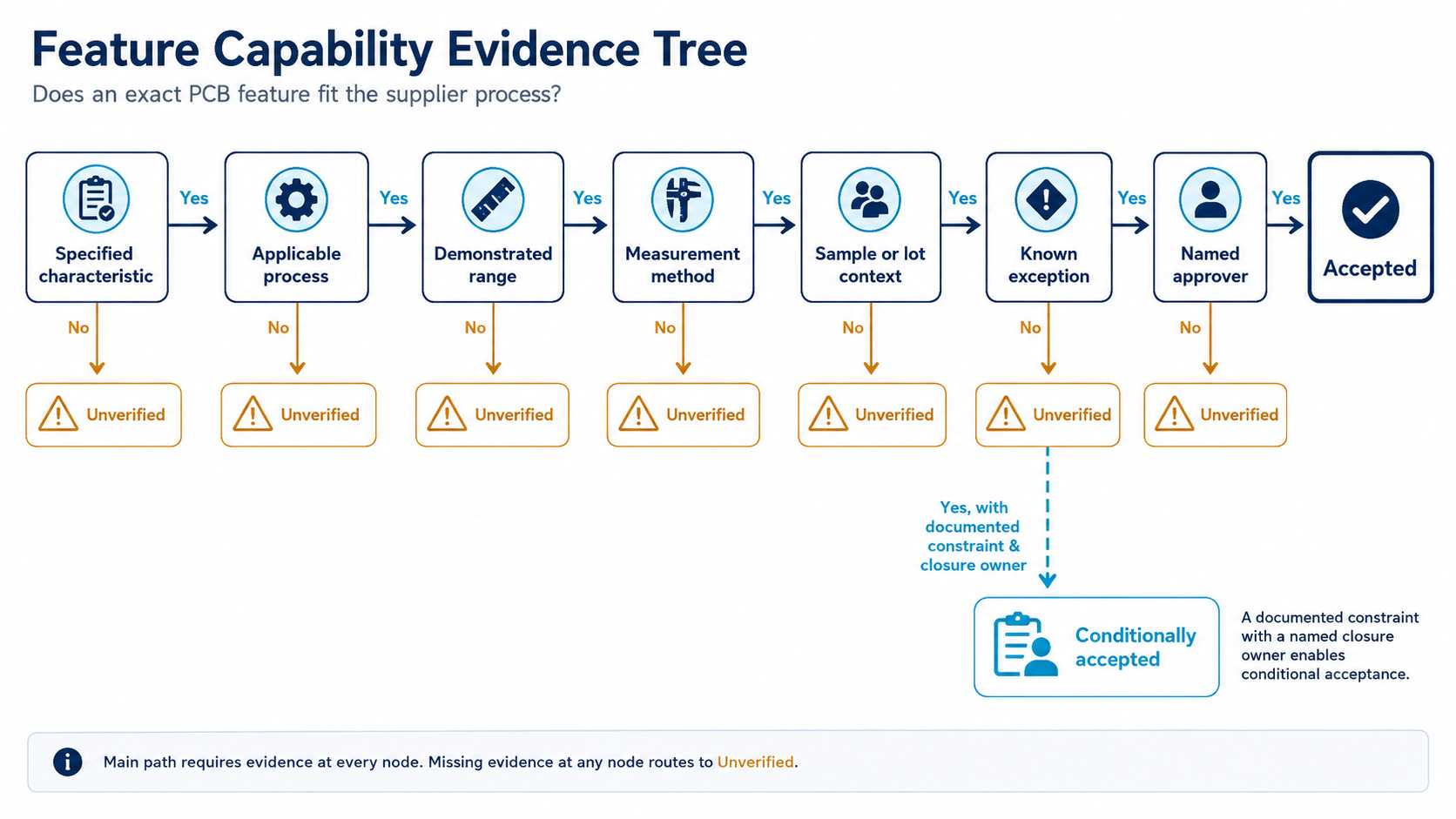
- Accepted: evidence exists that demonstrates that the characteristic meets both the defined process and acceptance method.
- Conditionally accepted: evidence exists that can be used, but only under specific constraints, with the closure owner and trigger named.
- Unverified: there is insufficient evidence for the issuance of production authorization.
Having produced similar boards previously may not be sufficient to substantiate process capability with respect to new products. Therefore, the supplier may need to provide additional evidence to establish capability for products featuring heavy copper, tight spacing, unusual via geometry, low-loss material, selective plating, or densely assembled components. Capability should also be established at the feature level for the released product.
Standards and What They Actually Prove
Each of the various standards used in industrial PCB production supports a different evidence layer and cannot replace the specific electrical, mechanical, thermal, software, or functional acceptance limits established for the product.
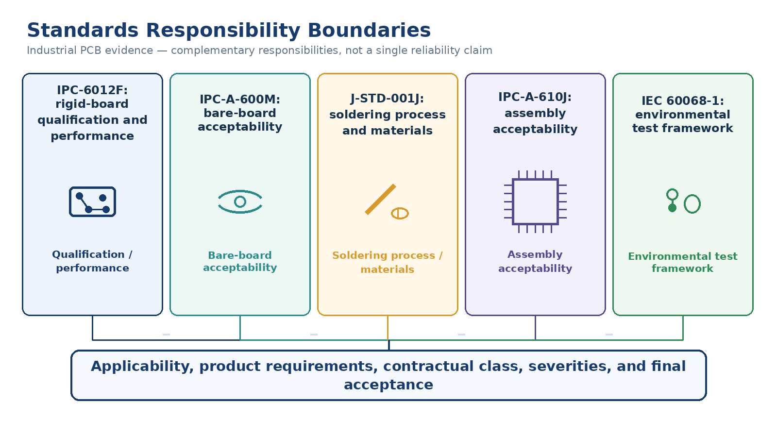
Visual acceptance on its own does not guarantee process control or finished-product function. According to IEC 60068-1:2013, environmental testing should be tailored to the expected conditions of transport, storage, and use, rather than to one level of industrial severity that applies universally. A major failure in interpretation can occur when these documents are combined incorrectly; i.e., quoting a J-STD-001J solder-process qualification and an IPC-A-600M Bare Board Visual Pass as sufficient proof of IPC-A-610J Assembly Acceptance, without providing the intermediate evidence that the actual post-assembly workmanship met the contracted criteria.
Pilot Evidence Before Volume Release
A prototype is primarily concerned with testing whether the concept can function as intended. A production-intent pilot is focused on determining if the planned baseline, site, tools, programs, materials, controls, inspection route, and acceptance method can produce repeatable evidence. The pilot quantity should be based on the questions that are being answered and the sampling basis. Using a single fixed number would fail to address the level of product risk, process maturity, or relevant characteristics being evaluated.
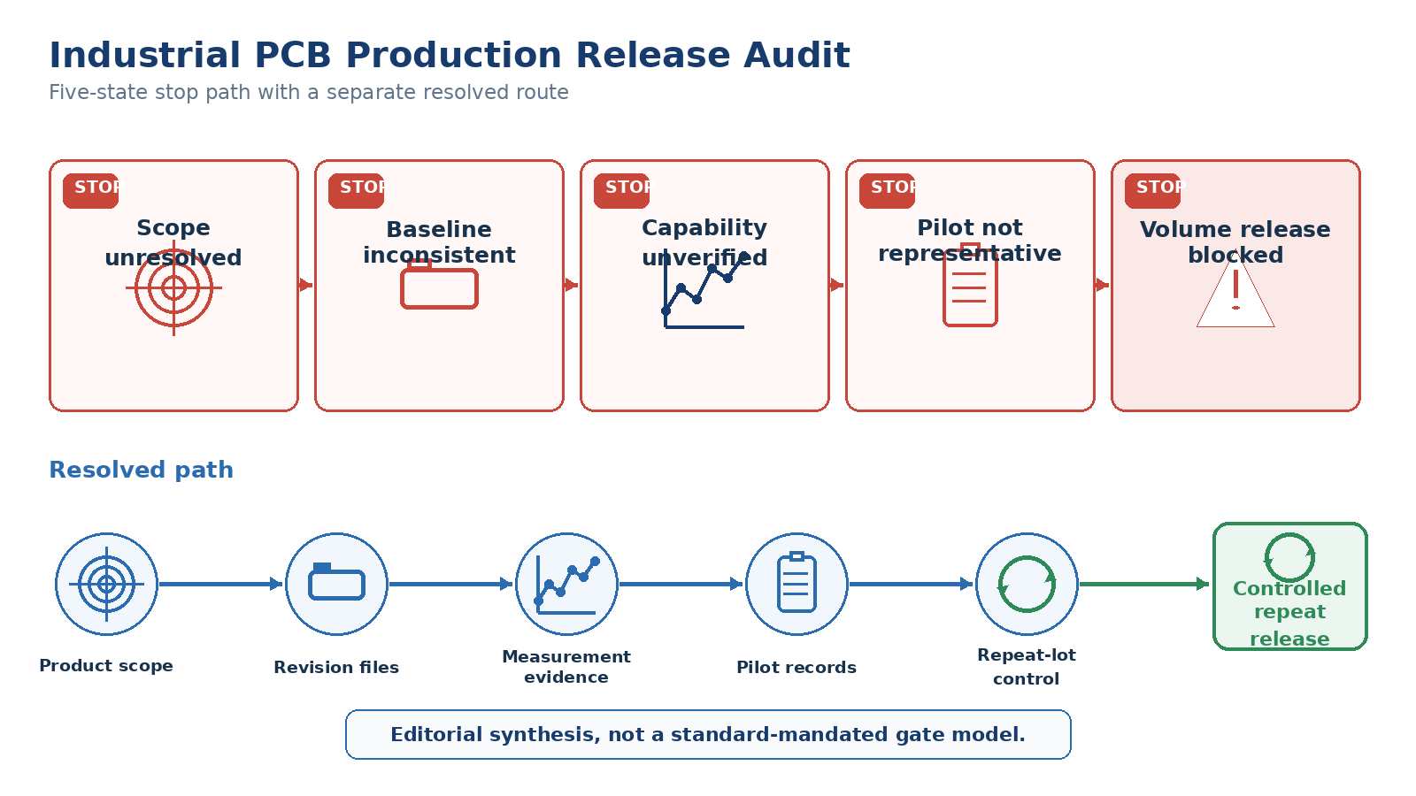
While a reworked unit may be acceptable as evidence for that unit’s disposition if it passes, it does not automatically validate that the unchanged process that created the unit will produce the same results when that process is repeated. Pilot evidence is not representative of full production until it has been verified to match the intended production state and any deviations are fully controlled and understood.
Does the Process Stay Stable Across Repeat Lots?
The fact that a sample meets the conformance requirements does not necessarily mean that the process will continue to be stable across production lots. NIST’s e-Handbook places process stability before capability analysis; process capability indices such as Cp and Cpk are only useful when the process assumptions and stability are understood.
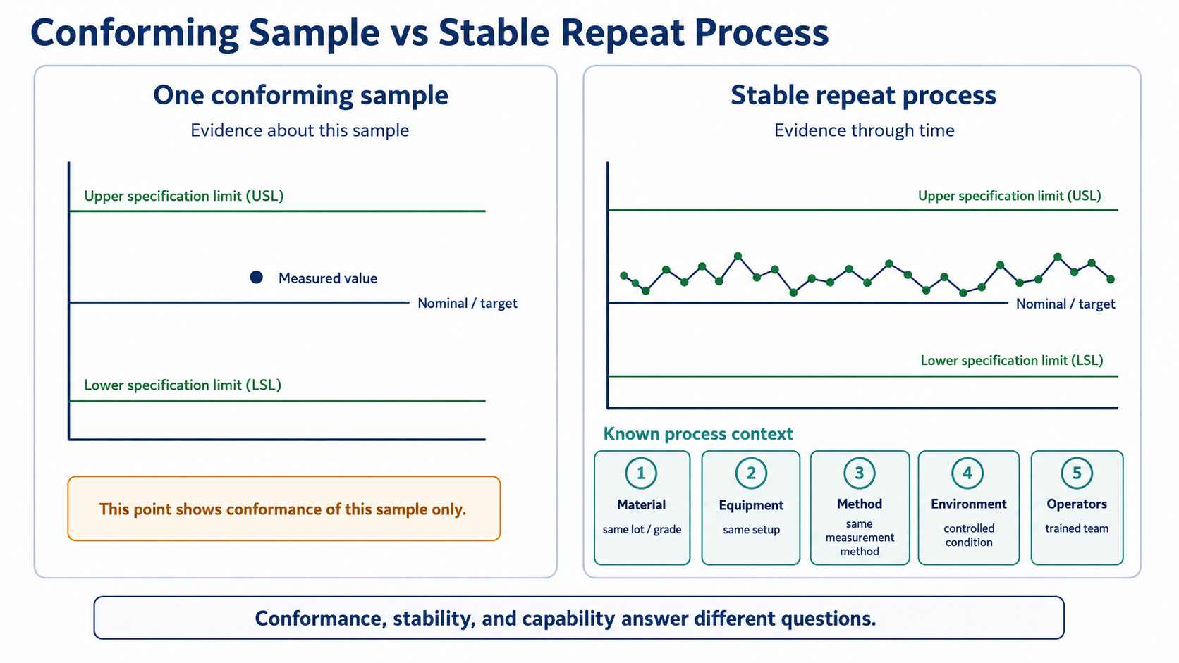
In determining the stability of a process, the time sequence must be preserved, known changes to the process must be identified, measured and sampled parameters must be documented, and a reaction plan with an assigned owner must be developed to address any unusual behaviour. To illustrate the importance of having sufficient observations over time, NIST’s example has more than 100 independent samples collected over a sufficiently long period. However, this is not a requirement for all manufacturers to collect the same number of samples. Each manufacturer should use sampling appropriate to the characteristics, measurement systems, production volume, risk, and contractual acceptance method.
Traceability links each unit or lot to the released configuration, material identity, production site, relevant process state, program, test result, deviation, and final disposition. IPC-2591 CFX Version 2.0, released in 2025, can support richer structured factory data, including information about PCB-vendor identification and recipe changes, but it is optional; the required outcome is still a traceable production record.
Changes to materials, components, suppliers, sites, panelisation, tooling, programs, production routes, or test methods are all capable of invalidating previously generated evidence. The manufacturer’s control plan should specify whether each of these changes requires document review, targeted revalidation, a new pilot, or a hold. As per IEC 62402:2019, obsolescence management is part of the overall lifecycle process; thus, replacement parts require an approved resolution and the required verification evidence instead of simply purchasing replacements.
Industrial PCB Applications
Factory Automation and Motor Control
Electronics used to automate factories include MCS, PLC, VFD, Servo Control Systems, Machine Control Packages, Safety I/O, Robotic Motion Control, and other Motor Control applications. When designing PCBs for motors and MCS products, designers may be faced with many varying characteristics that include switching power, electrical noise generated by motors, the length of field wiring, and sensitive control or communication circuitry. The PCB must be designed to handle these current paths, return currents, isolation requirements, thermal loads, connector stress, and EMC while remaining readily maintainable throughout the entire product lifecycle. The validation evidence from production should include stackup details, copper design, spacing between conductors, critical components, firmware, and functional testing associated with the released configuration. If changes occur in the Power Stage, Connector, Gate Drive Circuit, Filter, or Field Interface components, the revalidation plan must clearly identify which Thermal, EMC, Safety, or Functional validation evidence will be affected by the changes, rather than assuming that a replacement component will satisfy the same functional requirements simply because it physically fits.
Power Conversion and Energy Systems
Power electronics used in Industry include PSUs, DC/DC Power Converters, Inverters, Uninterruptible Power Supplies, Battery Charging Systems, and Energy Management equipment. Decisions regarding PCB design for these applications are typically driven by Current Density, Switching Frequency, Voltage Stress, Magnetic Components, Thermal Cycling, and Protection Characteristics. Although wider conductors or heavier copper can help to minimize electrical and thermal losses, this reduction in loss needs to be verified against the actual Cooling Path and physical geometry of the PCB. Design decisions regarding spacing and insulation for High Voltage areas on the PCB must comply with the appropriate Safety Standards, and switching nodes must also use layout controls to minimize EMI and overshoot.
The manufacturer’s production process should include a systematic means of tracking critical components, thermal interfaces, magnetics, firmware limits, protection thresholds, and functional load tests, as even seemingly inconsequential substitutions may significantly alter thermal performance, loss characteristics, transient response, or compliance margins.
Sensors, Measurement, and Industrial Networking
The coexistence of low-level analog signals with processors, isolated power sources, high-speed serial links, or long cables located near electrically noisy plant equipment can make signal integrity, grounding, filtering, controlled impedance, isolation, leakage, connector protection, and calibration more significant than raw copper thickness. It is recommended that the production environment preserve the validated PCB stackups and routing designs, identify accuracy-critical or calibration-sensitive components, and associate each PCB with the corresponding firmware version and test limits defined by the manufacturer. If the performance of the PCB requires impedance, timing, analog gain, isolation, or calibration, inspection alone is not sufficient to demonstrate proper functionality; therefore, the evidence of acceptance must include measurements taken to demonstrate those requirements.
Transportation and Infrastructure
Rail equipment, charging infrastructure, traffic systems, building control systems, remote monitoring systems, and related equipment can subject electronic devices and components to temperature cycling, vibration, extended time between maintenance, power disturbances, and long service lives. For this reason, production should preserve the configuration and manufacturing controls that supported the initial environmental, EMC, safety, and functional acceptance rather than assuming that later lots remain equivalent automatically. Materials, connectors, mounting, coating or sealing strategies, power protection, and environmental validation should match the actual installation rather than a generic industrial profile.
Because of the extended service life of these products, the probability of components being discontinued or suppliers changing is much greater, so the approval process should include identifying approved alternative components, maintaining traceability for components used in production, procedures to address component obsolescence, and the process for revalidating changes when required.
Release, Hold, or Rework the Production Plan
Volume production is justified only when the following are closed together: Requirements; Production Object; Baseline Reconciliation; Critical Feature Capability; Representative Pilot Evidence; Repeat Controls; and Change Rules.
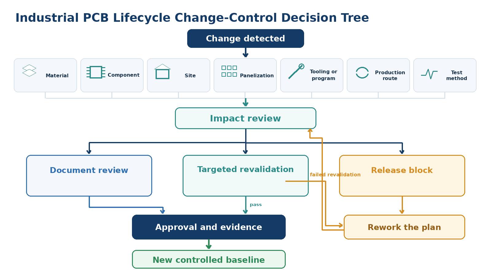
The release logic for both in-house production and outsourced production remains consistent regardless of who performs the actions or which company performs them. OEMs, EMS providers, contract manufacturers, board fabricators, software teams, and test owners may have a variety of responsibilities throughout the lifecycle of a product; therefore, while responsibility is shared among them, acceptance boundaries and ownership of acceptance evidence must remain clearly defined.
SUGA-PCBA provides a corresponding perspective on manufacturing support for production programs where assembly is also being done by an external supplier.
References & Sources
- IPC-6012F, Qualification and Performance Specification for Rigid Printed Boards – IPC
- IPC Status of Standardization – IPC-A-600M, Acceptability of Printed Boards (May 2025) – IPC
- IPC Releases J Revisions to J-STD-001 and IPC-A-610 – IPC
- ISO 10007:2017, Quality management – Guidelines for configuration management – ISO
- IPC-2581C, Printed Board Assembly Product Manufacturing Description Data and Transfer Methodology – IPC
- IEC 60068-1:2013, Environmental testing – Part 1: General and guidance – IEC
- NIST/SEMATECH e-Handbook: Assessing Process Stability – NIST/SEMATECH
- NIST/SEMATECH e-Handbook: What is Process Capability? – NIST/SEMATECH
- IPC-2591 Connected Factory Exchange (CFX) Version 2.0 release – IPC
- IEC 62402:2019, Obsolescence management – IEC
- Texas Instruments AN-2020, Thermal Design By Insight, Not Hindsight – Texas Instruments
- How Millions Of Printed Circuit Board Are Made Inside Mass Production Factory – The Factoran