Upload BOM & Gerber
-
Mobile: +86 13312967631
-
Email: sales@sugaintl.com

Low Volume PCB Assembly Services
China Low-Volume PCB Assembly Factory for OEM Small-Batch PCBA
Low volume PCB assembly gives engineering and purchasing teams a controlled way to move from design qualification into repeat production without committing to mass-production quantities. We coordinate engineering data, component sourcing, mixed SMT/THT assembly, inspection, FCT, and batch traceability through one coordinated manufacturing sequence.
1–250 Unit Batches
Repeat Production Beyond 5,000
±30 μm Placement
0.2 mm BGA Pitch
What Is Low-Volume PCB Assembly?
Low-volume PCB assembly gives control over PCBA production to engineering teams and purchasing teams so they can individualize their PCBAs at the proper point in the design qualification process. It supports product variations in small volumes (pilot demand, bridge supply) while allowing for repeatable production through a history of production records.
Typical Batch Range
Typical low-volume batches of PCBAs range from 1–250 units per batch. Repeat production of the same PCBA can be executed in excess of 5,000 units while using the same BOM, process, testing, and batch tracking procedures as the previous low-volume production.
What Makes a Batch High-Mix?
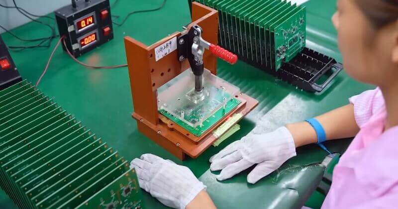
A 100-board production run with one stable BOM and a common reusable test program can behave like repeat production. The same quantity spread across ten different BOMs, various component differences, and different firmware versions creates a high-mix batch and will have a dramatic effect on productivity and manufacturing efficiency. While the actual quantity produced is important, the variations in production methods and the reusability of materials and test programs are more important.
With production-grade repeatability, SUGA designs each order around the nature of the mix and the time required to prepare, rather than the actual number of boards.
Production-Grade Repeatability
Production-quality low-volume assembly differs from one-off prototype soldering in that the line data, material identification, first-piece results, inspection programs, and test limits must all be related to a repeatable configuration.
A low-volume batch can demonstrate repeatable assembly, known defect modes, and usable test coverage. However, it is not sufficient to establish full product certification, long-term field life, system-level operation, or sustained high-volume throughput. These determinations must be supported by separate product, reliability, regulatory, or capacity evidence.
How Does Low-Volume PCB Assembly Work?
Low-volume PCB assembly progresses through four controlled stages: manufacturing data alignment, engineering analysis, component kitting, and configured production. During each of these stages, the materials, programs, inspection, and test results are all tied to the same product version so that valid production assets can support the next order.
Manufacturing Data Package
The Manufacturing Data Package must also describe the same product version (Gerber or ODB++ files, BOM, centroid file, assembly drawing, quantity, firmware, test instructions, labels, packing information, cable or enclosure data, etc.). Misalignment in the centroid file can result in correct parts being placed in the wrong locations. An old BOM may also allow the inclusion of components that no longer align with the current firmware.
When Engineering has one controlled set of manufacturing data, it can perform accurate CAM processing, purchase components, and develop the appropriate tooling, programming, and inspection based on that controlled data. This will also prevent late document changes from impacting only a single production team.
Engineering Data Analysis
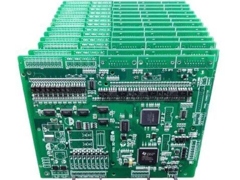
Engineers analyze footprints against BOM packages, check polarity and orientation, assess tooling and panel constraints, identify conflicts with assembly or electrical access, and convert discrepancies into production instructions before materials and tooling are committed.
Component Kitting
Low-volume orders may combine customer-supplied parts with parts sourced by SUGA. The BOM is the point of material control. All authorized alternates, lot identification, incoming condition, shortages, and excess material are linked to each line item.
Moisture-sensitive devices, for instance, must be handled correctly, and substitutions must be documented with proper authorization.
There is no uniform distribution of material exposure across the BOM. Standard available parts will fit within the normal lot control system. Long-lead or allocation parts require a supply commitment, and there must be identifiable and approved alternatives. Single-source or end-of-life parts require a continuity decision. Critical consigned parts require setup allowance, attrition allowance, and storage conditions.
Unused components can be returned at the end of an order, held in reserve for a repeat batch, or used towards a future agreed-upon quantity. If a customer-supplied kit is short, production can proceed only on the basis of an agreed-upon partial quantity, supplementary sourcing, or revised scheduling.
Production Sequence
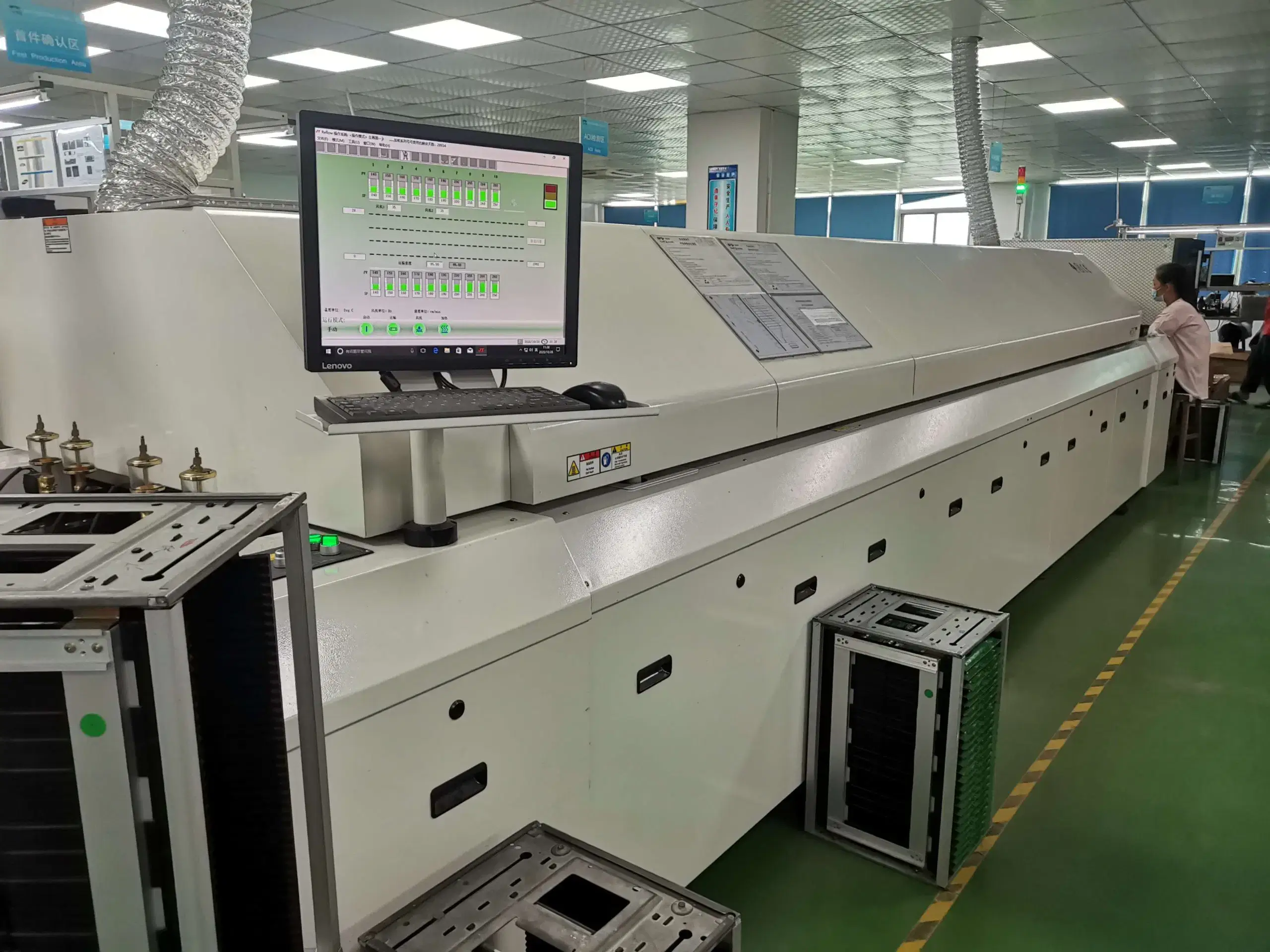
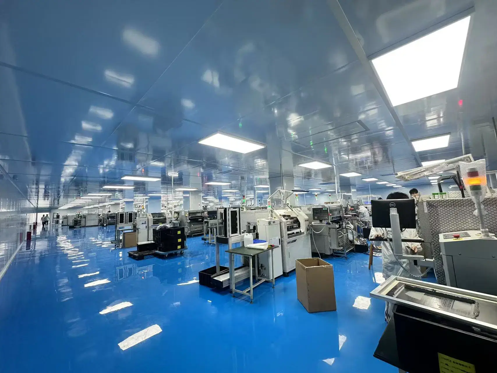
When engineering and material status are clear, production prepares the stencil, machine programs, feeders, work instructions, and first-piece inspection. SMT placement, reflow, THT insertion, selective or manual soldering, inspection, electrical testing, FCT, programming, labeling, and packing will proceed in accordance with the defined assembly sequence.
A small-batch failure generally originates from outside the soldering process; for example, an initial unit might have a temporary wire modification that is not entered into the manufacturing data. In addition, the test assets may not arrive until after assembly, or a deviation from the prior batch may carry into the new version of the product. Each exception must continue to be linked to the current batch so that it cannot become an undocumented standard.
From Prototype To Repeat Production
| Production Type | Primary Objective | Data Maturity | Process Control | Test Results | Change Tolerance |
|---|---|---|---|---|---|
| Prototype | Demonstrate circuit function, interfaces and firmware | Frequently changing | Adaptive setup with fast engineering feedback | Basic inspection, programming and defined functional checks | Highest; changes are expected between builds |
| Pilot Production | Demonstrate manufacturability and repeatable assembly | Partially controlled | First article, process-window confirmation and controlled deviations | Repeatable inspection and test records | Controlled; changes require documented analysis |
| Bridge Production | Supply early or uncertain demand before dedicated volume production | Mostly stable | Repeatable production setup with material-risk and capacity planning | Batch-comparable results and defect history | Limited; only necessary changes should enter the batch |
| Repeat Production | Maintain recurring small-batch supply | Stable production data | Reusable programs, tooling, controlled BOM and test assets | Comparable batch results and deviation history | Formal ECO control |
Prototype PCB Assembly
The first boards manufactured reveal potential problems due to schematic errors, a poorly designed layout, unexpected thermal performance, and connector problems that cannot be isolated through simulation. In the prototype phase of manufacturing, rapid iterations will help keep findings associated with design modifications separate from production evidence while the design is still changing.
Pilot Production
During the pilot production phase, the outputs from the engineering work related to the prototypes are compiled into a repeatable process, along with supporting metrics for manufacturing success or failure. A functional first board does not show that engineering has produced a repeatable process, as evidenced by differences in component placement, soldering methods, and test results.
A good pilot production plan should closely match the intended repeat-production configuration. This includes PCB material, finishes, solder alloys, their sources, the support provided to the PCB panel, stencil design, the programming method to be used, and the test interfaces to be used with the final product. Engineering learning through the use of temporary fly wires, lab-only substitute parts, manual placement of components, and experimental test limits supports pilot production; however, these must be kept separate from the evidence that establishes repeatable manufacturing processes.
Bridge Production
Bridge production continues with pilot setups while manufacturers begin to consume material inventory and production capacity due to actual demand for the product. To establish repeatable manufacturing processes, it is necessary to compare the next production run with the evidence from the previous production run to separate remaining product changes from manufacturing variation before moving to dedicated volume manufacturing.
Repeat Production
When PCB data, BOM, centroid, assembly drawing, firmware, and test methods are synchronized, moving from small-batch production to repeat production is appropriate. Rework is no longer supporting unstable yields, corrective actions for recurring defects have been closed, and critical parts and alternates are stable; therefore, the same process conditions can be used to produce similar results on the next lot. No single yield percentage defines that transition for every product.
High-Mix Low-Volume Production
The high-mix low-volume production model is successful when controlled setups enable multiple variants, rather than when operators use memory for setup.
| Production Area | Supported Range | Project Condition |
|---|---|---|
| Order / production range | 1–250 units, supports 5,000+ | Configure capacity by variant mix and repeat schedule. |
| Packages / placement | 0201, QFN, BGA, CSP, PoP, fine-pitch; BGA 0.2 mm pitch and QFP 0.15 mm lead width | Align land pattern, stencil, paste, inspection, and rework access. |
| Placement Accuracy | ±30 μm at 3σ | Use calibrated placement programs, board support, and package-specific setup. |
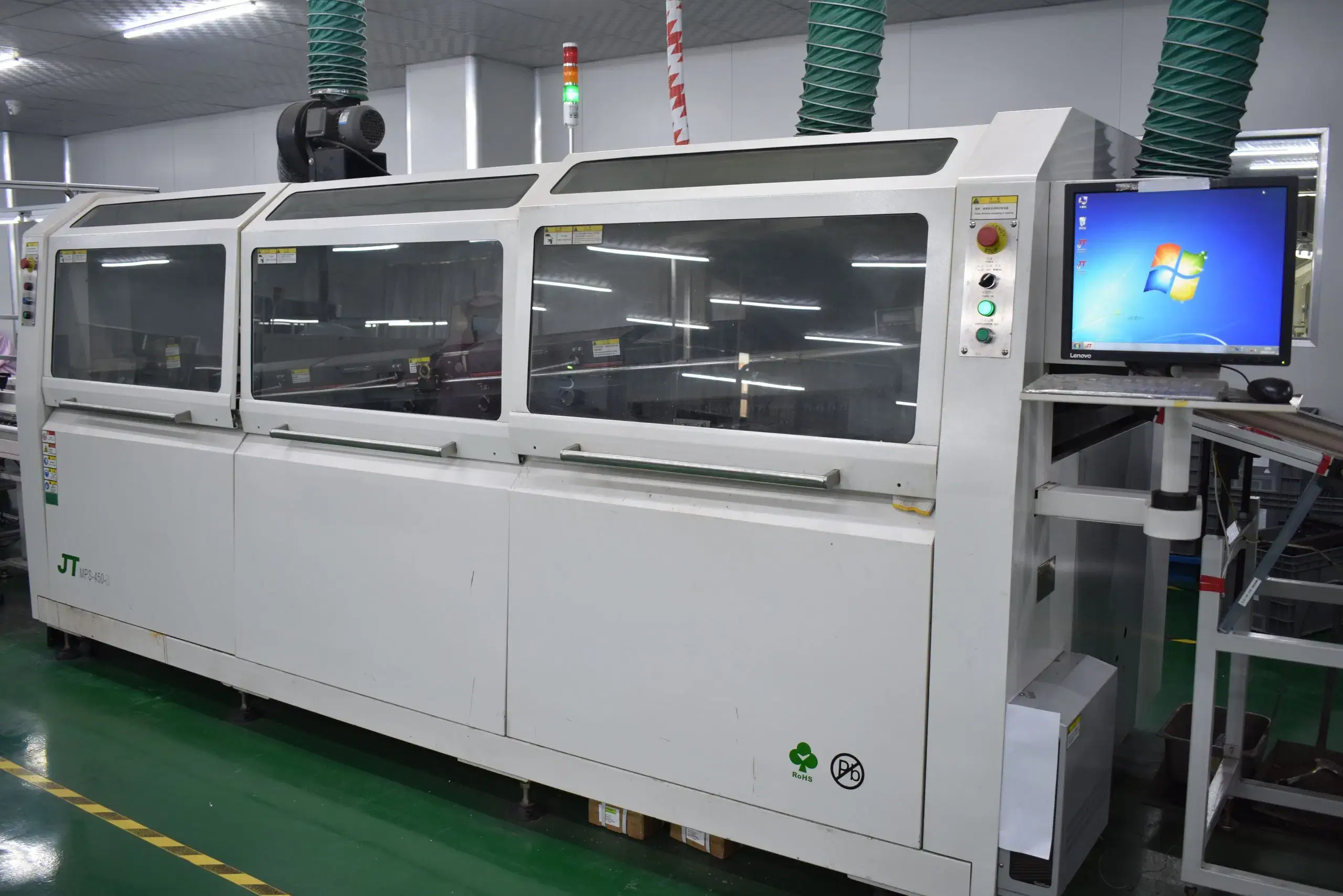
| Assembly methods | SMT, PTH/THT, mixed technology, single/double-sided, BGA on both sides | Sequence heat-sensitive and mechanically loaded parts deliberately. |
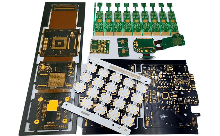
| Board Compatibility | Rigid, flex and rigid-flex boards; supported odd shapes, cut-outs and board-specific carrier requirements | Panel support, tooling clearance, warpage, connector overhang and carrier design determine the setup. |
| Stencil And Soldering | Laser-cut stainless-steel stencils; lead-free and leaded soldering; selective soldering and controlled hand soldering | Select solder alloy, flux, profile and manual operations according to component limits and the defined workmanship class. |
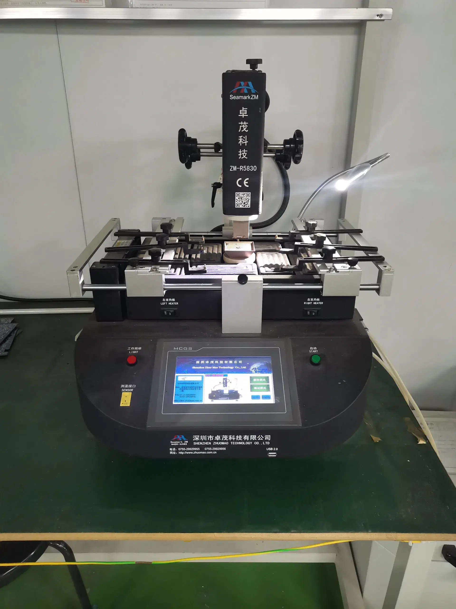
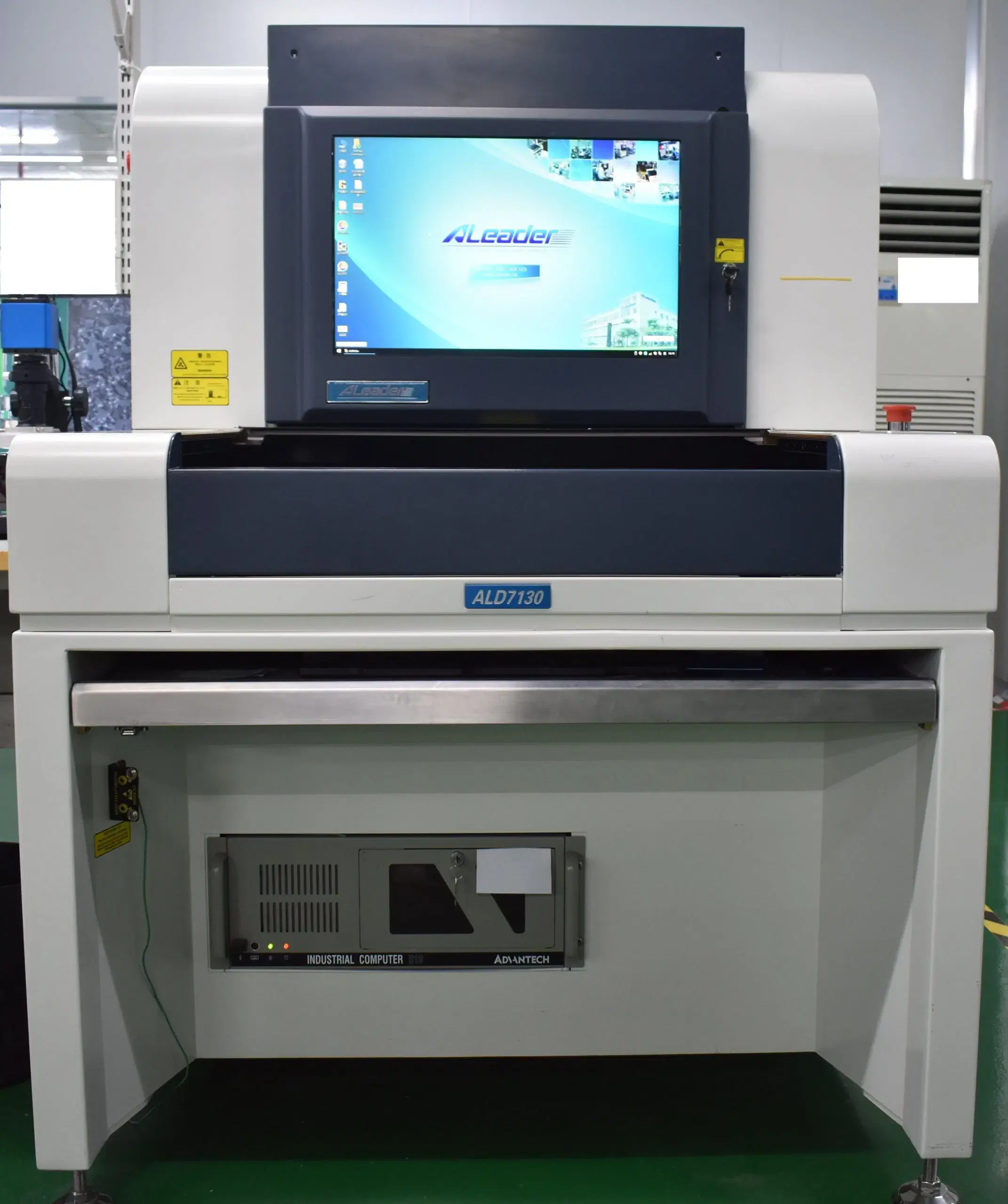
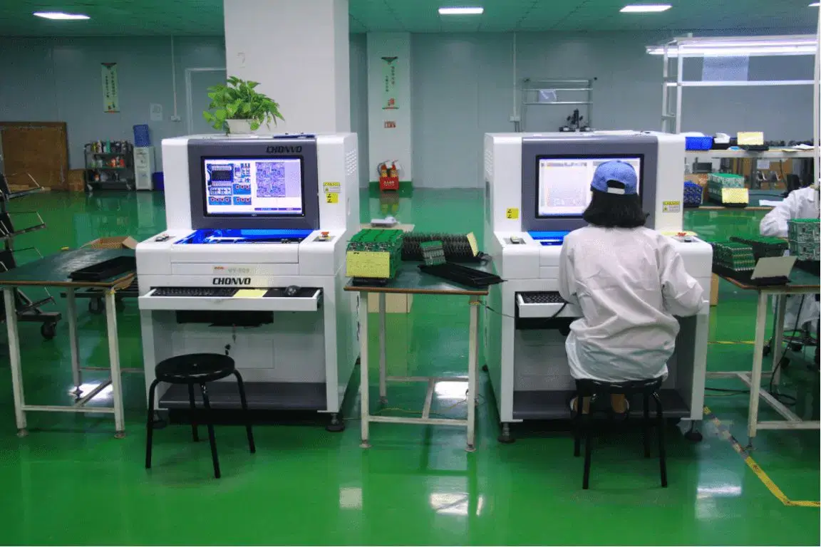
| Inspection And Testing | 100% visual inspection; AOI, SPI, X-ray, flying probe, ICT, FCT and programming assigned by board construction and test coverage | Match each method to the target defect and required results. |
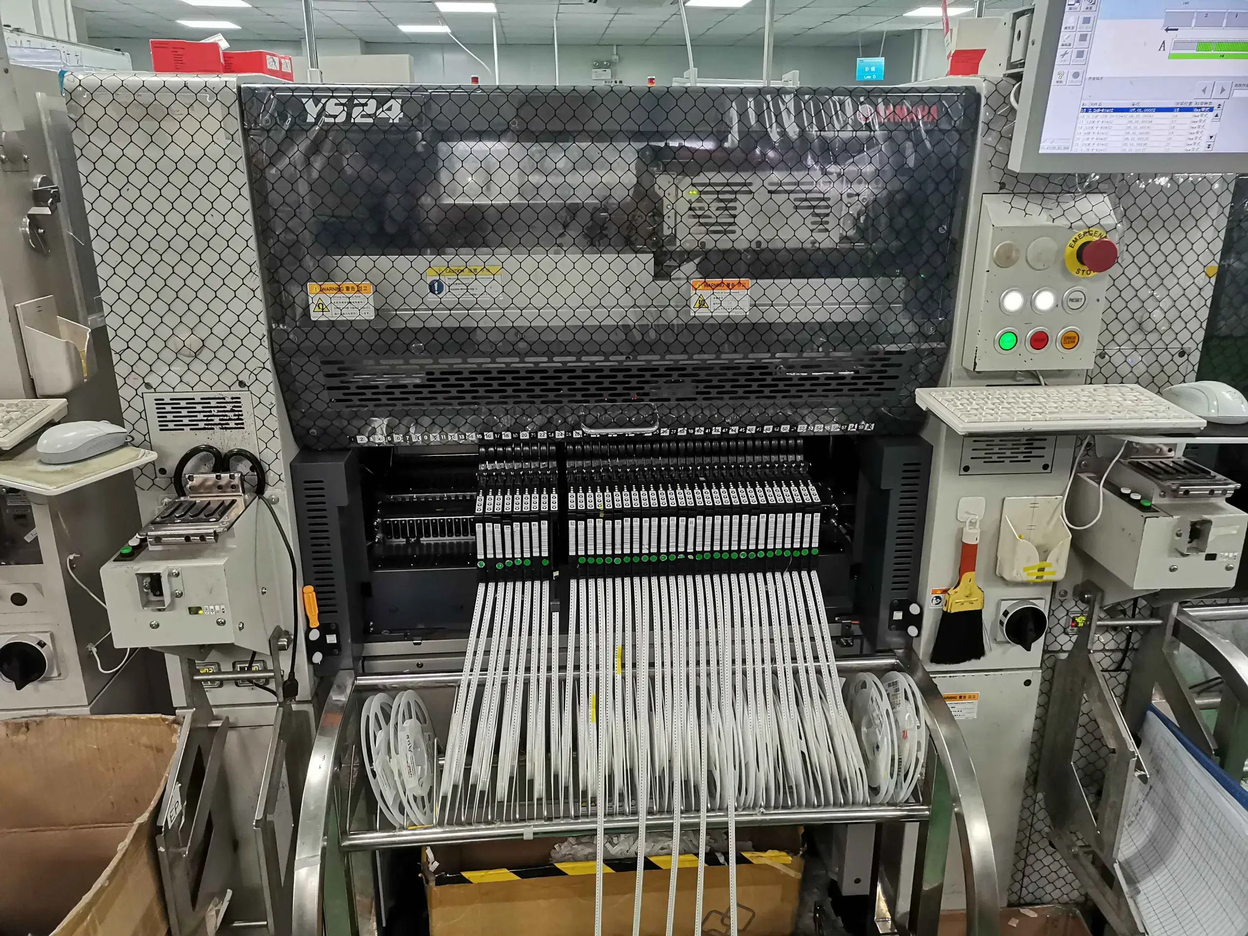
Feeder Changeovers
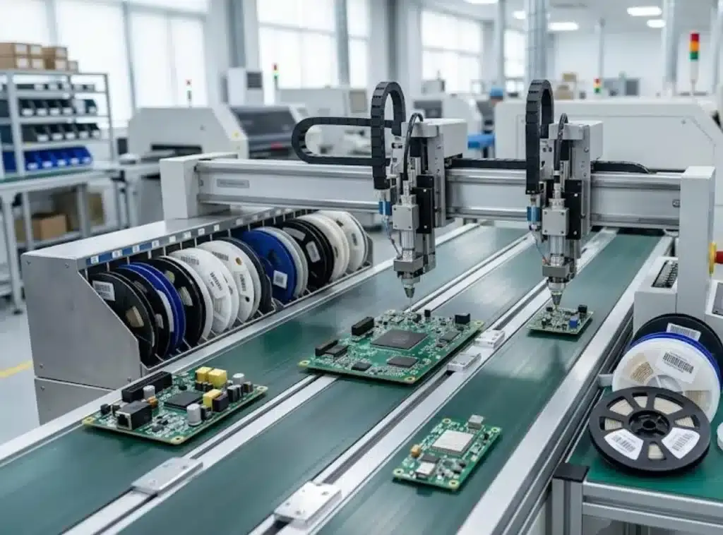
When changing a variant, numerous parameters may change, such as the BOM, feeder map, stencil, placement program, inspection program, or soldering sequence. If a feeder change is completed from memory rather than from a verified checklist, an operator may not remove a reel from the previous variant. The assembly appears correctly populated, and the error may appear only during electrical testing or after shipment if that position falls outside the test plan. Operators clear the previous setup, load materials and programs for the new run, and compare the first piece against the work instructions before proceeding.
Which Packages Need Fine-Pitch Process Control?
The nominal placement accuracy considers only component positioning, not the complete fine-pitch process window. For example, at 0.2 mm BGA pitch or 0.15 mm QFP lead width, a stencil aperture sized correctly for one footprint may under-release paste on an adjacent footprint, and the adjacent joints may be too close together for selective rework; thus, a bridge created by this geometry will require replacing the entire component rather than touching up one lead. Solder deposition, board stability, inspection visibility, and rework feasibility must be qualified together and not assumed based solely on component placement accuracy.
Board Support Across Assembly Types
The geometry of a PCB will determine how that board is supported throughout all assembly processes, i.e., printing, placement, reflow, insertion, and separation. During reflow, a panel that contains cut-outs or unsupported areas may flex by a fraction of a millimeter, creating enough variation in solder height along one edge of a BGA to open a joint that had no defect upon placement. The carrier, tooling clearance, and panel support must be established based on board geometry, rather than using one standard fixture for all products.
Variant And Revision Control
The BOM, centroid file, stencil, feeder setup, placement program, work instructions, and inspection program must all reflect the same current production revision. Simply loading the correct component against an old centroid does not constitute a correct production process. In addition to traceability back to a specific production revision, revision-to-batch traceability provides a means of identifying the cause of the problem before products from two different variants become mixed.
Variant control includes firmware, label content, test limits, enclosure pairing, and packing identification. Physically separating the products, using separate work instructions, identifying the products by barcode or traveler, and maintaining line-clearance records will reduce the chance of two visually similar assemblies being placed in the same tray or shipment. The only assets that move to the new revision are those impacted by the variant change, while all other shared assets remain unchanged and traceable.
PCB Assembly Inspection And Testing
No single inspection method will confirm all aspects of PCB assembly quality. Each method identifies different types of defects; therefore, the inspection and testing sequence should follow the joint geometry, electrical access, firmware, functional risk, and defined pass/fail limits of the assembly.
| Assessment Area | What It Confirms | Production Purpose |
|---|---|---|
| DFM/DFA/DFT | Pad, mask, stencil, polarity, panel, assembly access, test-point, and programming-access risks are addressed | Prevent problems before production. |
| SPI and AOI | Paste deposition and visible placement or solder defects are detected | Separate visible defects from under-package joints. |
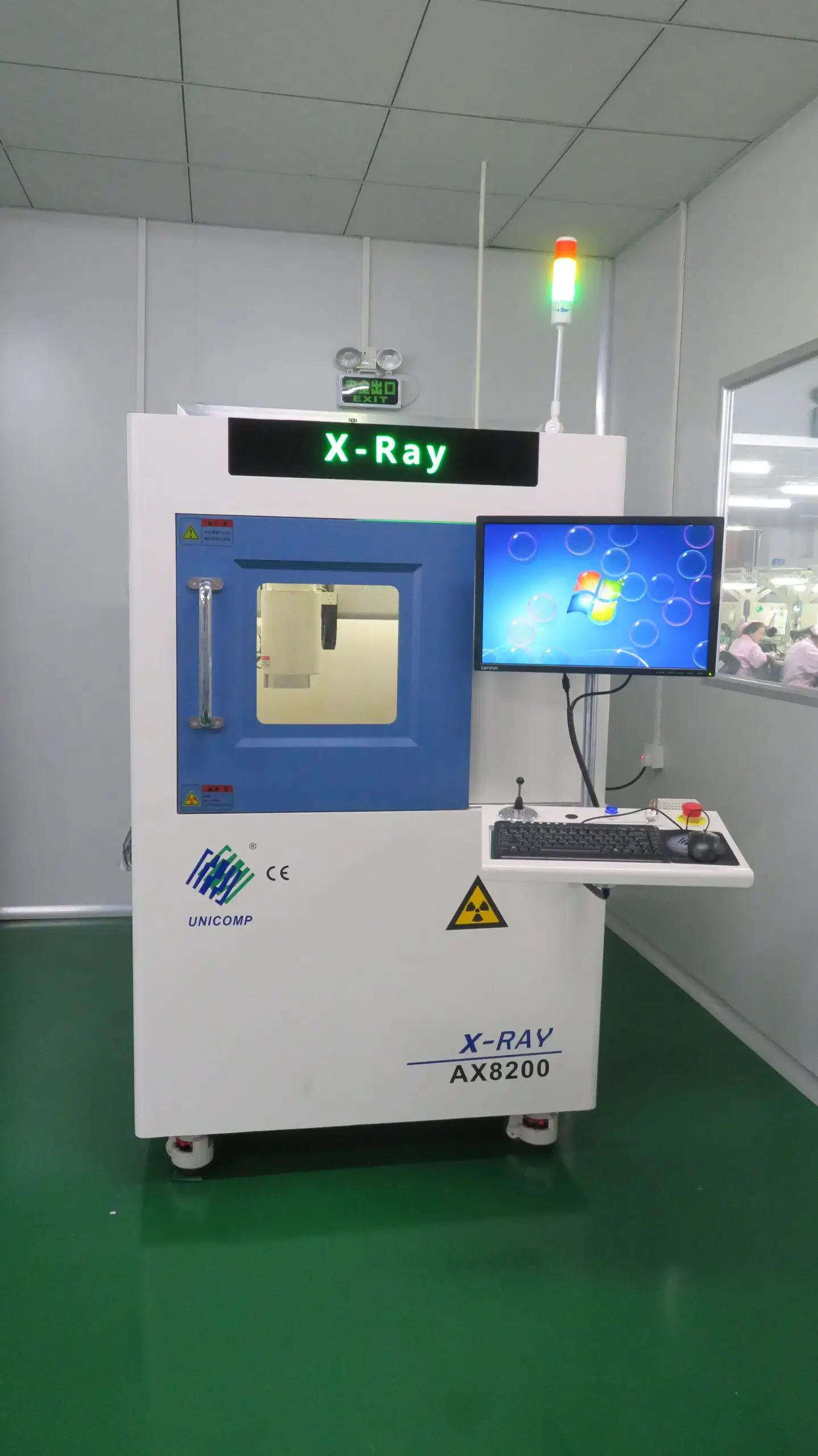
| X-ray | BGA/QFN/LGA under-package joints can be assessed for opens, bridges, and void signatures | Apply defined pass/fail limits. |
| Flying probe / ICT | Network continuity, shorts, opens, and configured electrical points are checked | Select by access, quantity, fixture economics, and coverage. |
| FCT and programming | Interfaces, firmware, loads, and functional logic are tested | Use the defined test plan and pass/fail limits. |
| First article and batch record | Component lot, inspection result, test result, deviation, and corrective action remain connected | Keep results specific to the batch identity. |
How Does DFM Reduce Assembly Risk?
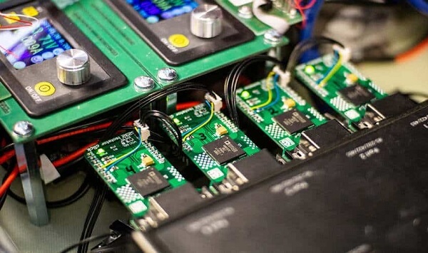
DFM verifies the compatibility of the pads, solder mask, panelization, and manufacturing process with the physical constraints of the assembly. DFA verifies that the assembly can be accessed, properly oriented with respect to polarity, easily supported from a mechanical standpoint, and processed in the most logical order. DFT verifies the presence of and access to test points, programming access, fixture interfaces, and measurable pass/fail conditions. Together, they allow us to eliminate preventable defects before beginning the setup.
Solder Paste Inspection
SPI evaluates solder paste deposition before components hide the pads. The subsequent operation is AOI, which evaluates visible placement, orientation (polarity), completeness (missing parts), positional alignment, and solder-joint characteristics. AOI cannot view beneath BGAs during visual inspection; therefore, it cannot provide proof of all solder connections.
Under-Package Inspection
X-ray provides a means to detect density changes in areas beneath surface-mount BGA, QFN, and LGA packages. X-ray can also be used to identify signs of opens, solder bridges, insufficient solder, and voiding. Engineers apply defined pass/fail criteria to those images because simply seeing a void does not automatically render it a failure.
Electrical Test Coverage
Electrical test coverage options depend on test-point accessibility, the economic viability of fixtures, the quantity of assembled PCB boards, product risk, and the amount of information that needs to be collected before shipment.
Flying probe electrical testing is typically more practical when quantities are small and documentation is changing because the cost of dedicated fixtures is prohibitive and cannot be spread over future orders. Conversely, if a single stable version returns multiple times, that version begins to become attractive for ICT when test points are available and test speed affects batch efficiency. FCT is needed when testing for network continuity alone is not enough to provide evidence that firmware, interface, load, sensor, communication, or control behavior is functioning correctly.
Flying probe and ICT electrical testing can identify an open circuit or a short circuit without verifying the full operational capabilities of the assembly. FCT can demonstrate that the processes identified by an operational procedure, such as a complete power-up sequence, are valid without locating every solder defect. Combining test options based on board layout and the consequences of a defect provides a better chance of achieving useful test coverage than always using a specific test type by default.
Batch Quality Records
The first article in a batch can contain information relating to component identification and orientation, critical package placement, solder paste and visible-joint results, firmware version, power-up current, and interface responses. The first article can contain information on how the batch was labeled, as well as the revision of the board.
Batch records include first-pass yield, rework quantities, retest results, repeated defect categories, and final dispositions. If defects are observed multiple times, the remaining assemblies will be held while the defect is investigated through the placement program, solder paste stencil, materials, work instructions, testing processes, or design documentation to determine how to correct the issue. The correction becomes part of the record for the current production run, so the next order does not restart from the same failure.
SUGA assembles PCBs under ISO 9001:2015-based controls, and acceptance criteria for assemblies are based on IPC-A-610J. The materials and processes used for soldering follow IPC J-STD-001J, IPC-7711/21D establishes the authorized procedures for rework, and IPC/WHMA-A-620F establishes the criteria for cable and harness assembly integration. All boards are subject to visual inspection.
Low-Volume PCB Assembly Cost Drivers
Low-volume PCB assembly unit costs increase when fixed preparation work is distributed across fewer accepted boards. The core calculation is: Contribution of NRE to each unit = Total Fixed Preparation Cost ÷ Accepted Production Quantity
| Cost Driver | Cost Mechanism | Cost Response |
|---|---|---|
| Setup, stencil, programming, feeder/line preparation | Fixed work is divided across fewer boards | Reuse only assets that match the current product version. |
| Components and sourcing | MOQ, long-lead supply, alternates, channel, and consigned handling affect landed cost | Coordinate material through one BOM. |
| Testing and fixtures | Per-board test, fixture, software, and operator time vary by coverage | Match coverage to product risk and reusable test strategy. |
| Rework, failure analysis, and scrap | Defects and engineering changes consume material and skilled labor | Contain defects before full-lot production. |
Fixed Setup Cost
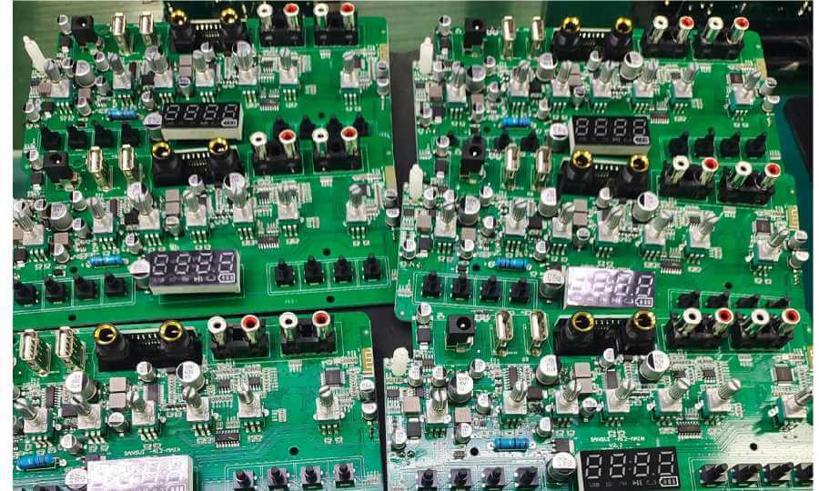
The fixed setup cost of a product is incurred once per setup and makes a decreasing contribution per unit as the quantity of accepted product increases. The fixed setup cost cannot be eliminated by rushing or removing the preparation component of a fixed setup process; instead, the risk is transferred to defects, rework, and schedule losses.
Reductions in cost can occur without eliminating the controls associated with a fixed setup process by scheduling variants with similar materials next to each other, combining forecast demand into planned batches, and using panel configurations that provide a stable method for handling and separating materials.
Component Sourcing Cost
The landed sourcing cost of components is based on the total cost to purchase, store, and control material. In addition to distributor pricing, the landed sourcing cost may also take into account available customer stock, SUGA sourcing under one BOM, moisture handling, and shortage exposure associated with the affected BOM line items.
Purchasing shared packages and approved parts can reduce fragmented purchases and feeder changes resulting from different part-number systems. By grouping forecast demand, supplier MOQ can be distributed across several planned batches instead of forcing each small order to carry the full excess quantity. Conversely, complex and lifecycle-sensitive parts introduced late in the production process may not provide savings because of the additional engineering, programming, testing, and traceability costs incurred by introducing a substitute material at that point.
Testing And Rework Cost
The cost of testing and rework is largely a matter of how early the defect is identified. By applying the required inspection and test coverage before full-batch production, companies can greatly reduce the material, rework time, and shipping capacity consumed by one defect.
Low-Volume PCB Assembly Lead Time
The last unresolved critical-path item will dictate the delivery date. Other parallel activities, such as material availability, engineering closure, stencil and program preparation, production-slot assignment, and test completion, allow partial overlap, but any missing dependency will put the entire batch on hold.
A typical expedited prototype-quantity assembly is performed within 24–72 hours after all required files have been received and the necessary materials and inspection requirements are ready. After engineering closure is complete, kitting has been accomplished, production capacity has been assigned, and test preparation is complete, standard low-volume assembly will be performed within 5–7 working days. Complex sourcing or fixture-dependent products should follow the material and test-preparation schedule.
Material Availability
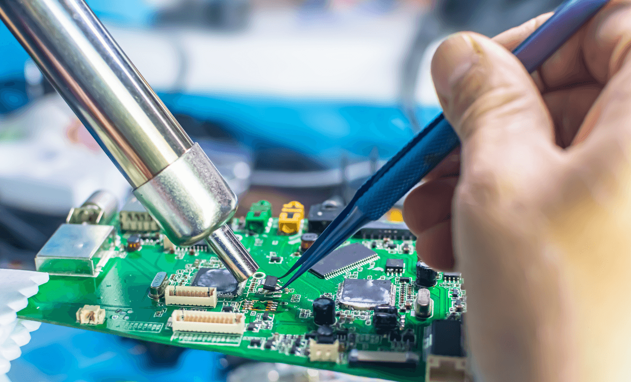
Material that is in stock will immediately proceed through incoming control and the kitting process. Materials with long lead times, incomplete consigned kits, or unauthorized alternatives cause scheduling delays. Once the BOM has stabilized, the supply chain can proceed with SUGA sourcing and customer-material checks concurrently.
A kit that is 98% complete can hold up the production process if it is dependent upon the remaining 2% for one or more processors, connectors, programmed devices, or other components required on all boards being assembled. Therefore, material readiness is dependent upon board-critical lines rather than just the number of BOM lines.
What Delays Production Scheduling?
Open footprint issues, ECOs, polarity conflicts, and changes in electrical access can all prevent the completion of stencil and program preparation. Once these issues have been resolved, tooling preparation and line-slot coordination become predictable. A nominally open line does not reduce production delivery time if the production data are still being modified.
Test Preparation Time
Fixture preparation, programming, test-software preparation, acceptance-limit definition, inspection-coverage preparation, and failed-unit handling procedures all consume calendar time. A short assembly cycle can still result in delayed shipment because of incomplete shipment records.
When interface definitions, firmware, expected loads, pass/fail limits, and sample data have been identified and are stable, test preparation and material procurement can run in parallel. If these items arrive after assembly, the finished boards will be delayed until the test software, test adapters, test fixtures, or engineering interpretation is available. The delay then falls under test definition rather than placement capacity.
Repeat-Order Scheduling
Preparation work for repeat-order items can be reduced if a valid stencil, machine program, controlled BOM, and test plan exist. Engineering can validate each asset against the current product version and identify any deviations from the previously tested product. Reuse will save time if it retains the same configuration as the previous time it was used.
Repeat-order scheduling can be improved further if the expected frequency of a given order, material reservations, remaining consigned stock, fixture condition, and known lifecycle changes are visible before the next demand date. This allows reusable assets to be put into use earlier in the preparation cycle, while critical items and test resources are assigned early enough to prevent assembly from becoming the only completed part of the order.
Low-Volume PCB Assembly Applications

Industrial Control Systems
Industrial control systems usually consist of a common platform used across multiple types of PLC components. These components generally include PLC I/O boards, sensor-interface boards, relay boards, terminal boards, and motor-control PCBs. While the same platform is typically used for multiple types of PLC boards, they may differ in channel count or connector set.
Substantial connector stress combined with field wiring can create a significant risk of failure in a joint that passed AOI and ICT. Thus, repeat-order records for these products can be more meaningful than the pass rate alone.

Medical Electronics
Medical electronics include patient-monitor interface boards, diagnostic sensor boards, and laboratory control boards, with many production-run assemblies being produced in low volumes. In most cases, the PCB assembly contains components specified for multiple versions or configurations of the same PCB. Therefore, component-lot identification, under-package solder inspection, device programming, and interface or sensor-response testing must remain aligned with the applicable build version.

Communication Equipment
Communication equipment, such as electronic-security boards, combines several different types of hardware, including high-speed connectors and interface circuits, clock or timing sections, programmed devices, and powered connections to communication sources. A substituted capacitor or crystal may pass FCT but still shift clock jitter or rail noise under load. Alignment and interface tests need lot-specific acceptance conditions.
Aerospace And Defense Electronics
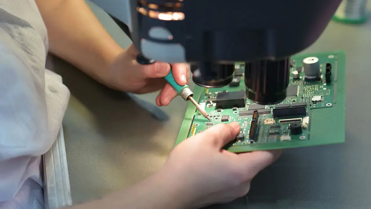
Electronics used in the aerospace and defense industries are often associated with limited production demand but require a thorough and stringent level of traceability to respective design changes. Connector retention, coating requirements, thermal exposure, and vibration-oriented conditions can change the required inspection and FCT coverage, while change-specific records remain associated with each manufacturing lot.

Automotive Electronics
ECU development boards, control modules, and sensor boards go through numerous ECOs before advancing toward repeat production. Controlled pilot and bridge assemblies maintain consistency in connector continuity, firmware programming, power-up current, I/O response, FCT, and ECO history; as such, documentation from the initial build can remain applicable to a repeat-production lot.
Power And Energy Control
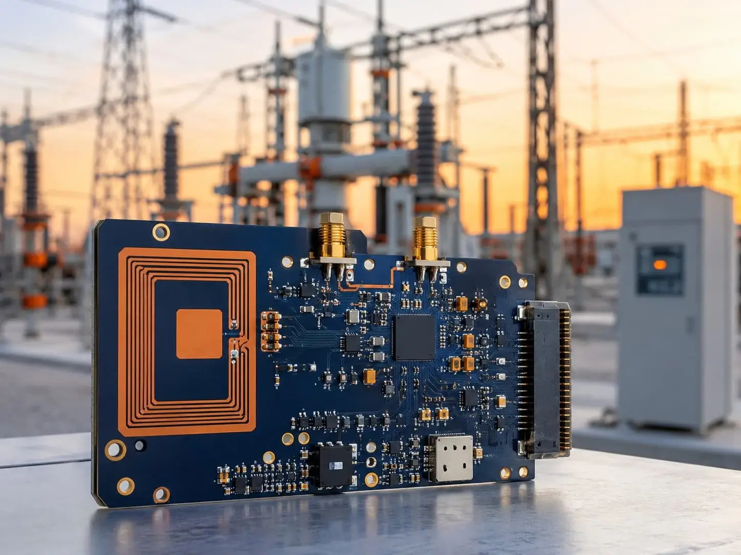
Power-conversion and energy-control boards contain components that handle high currents and are therefore subject to thermal and electrical constraints during assembly. Assembly requires attention to solder alloy, copper heat spreading, component clearance, thermal inspection, and load testing. Inspection of a newly assembled board may not guarantee operation under its intended load.

Connected Home And IoT Devices
Connected-home and IoT device electronics use small electronic boards, wireless communication systems, low-power devices, and periodic releases of new or updated features. Low-volume PCBA supports programming and interface testing while hardware and firmware changes remain active. The production record allows the radio module, firmware image, and enclosure variant to remain synchronized.
Scientific Instrumentation
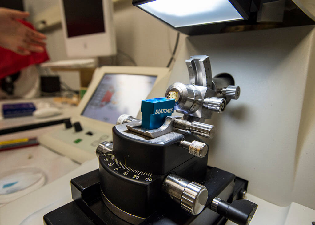
Scientific instruments consist of sensor acquisition, measurement interfaces, calibration connections, and limited yearly demand.
Although an alternate component may match every electrical parameter, the calibration curve may shift because of differences in packaging or parasitic effects.
Low-noise handling and connector integrity are more important than raw line speed.
Long-Lifecycle Equipment
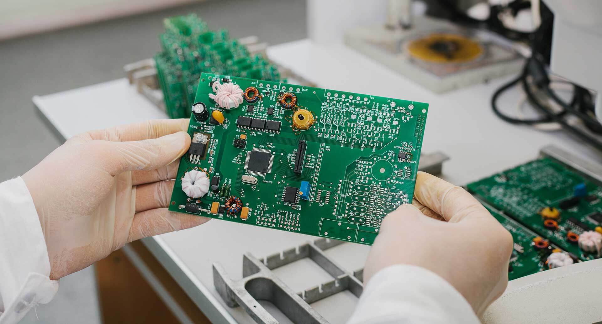
HVAC, transportation, and specialized B2B equipment will require only small lots of replacement parts over an extended period.
For equipment with multiple maintained versions, authorized substitutes, older tooling, and spare-part continuity must remain connected so that replacement boards stay aligned with the original installation.
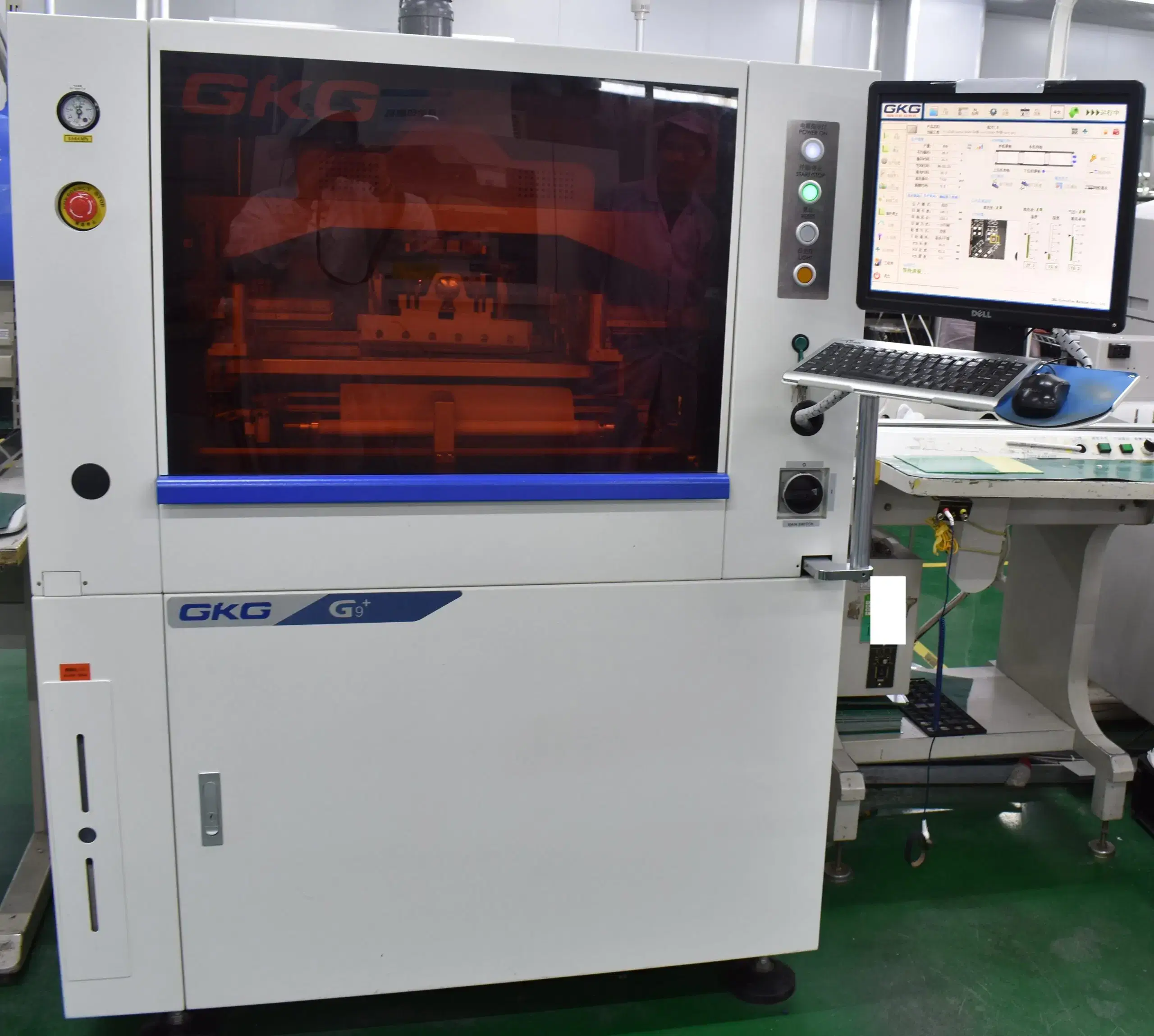
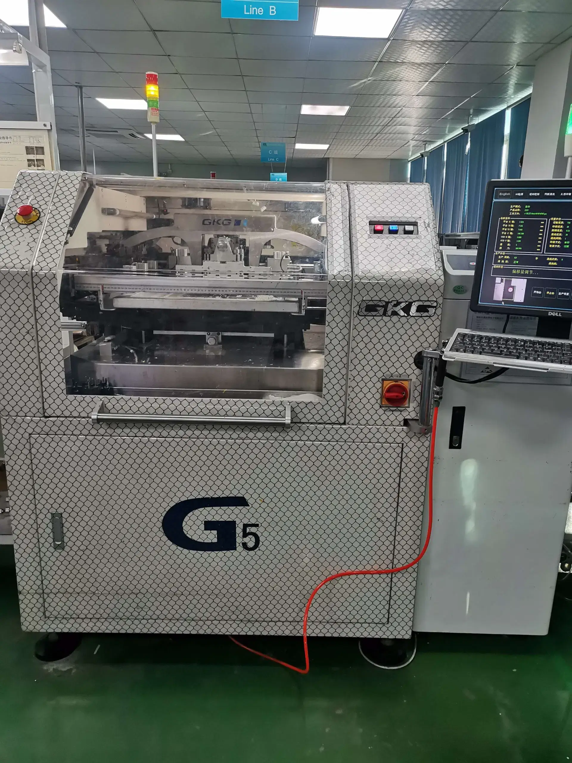
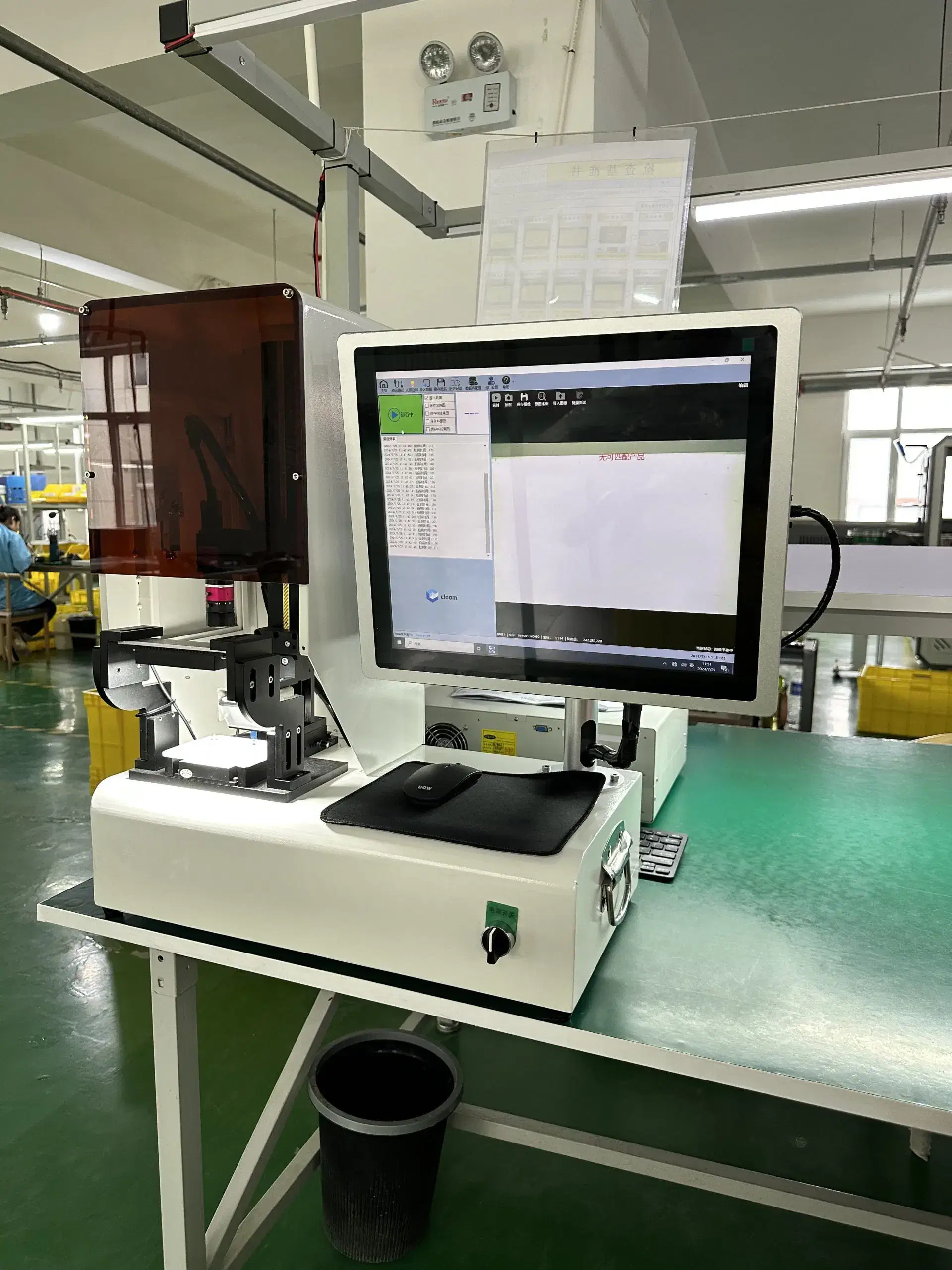
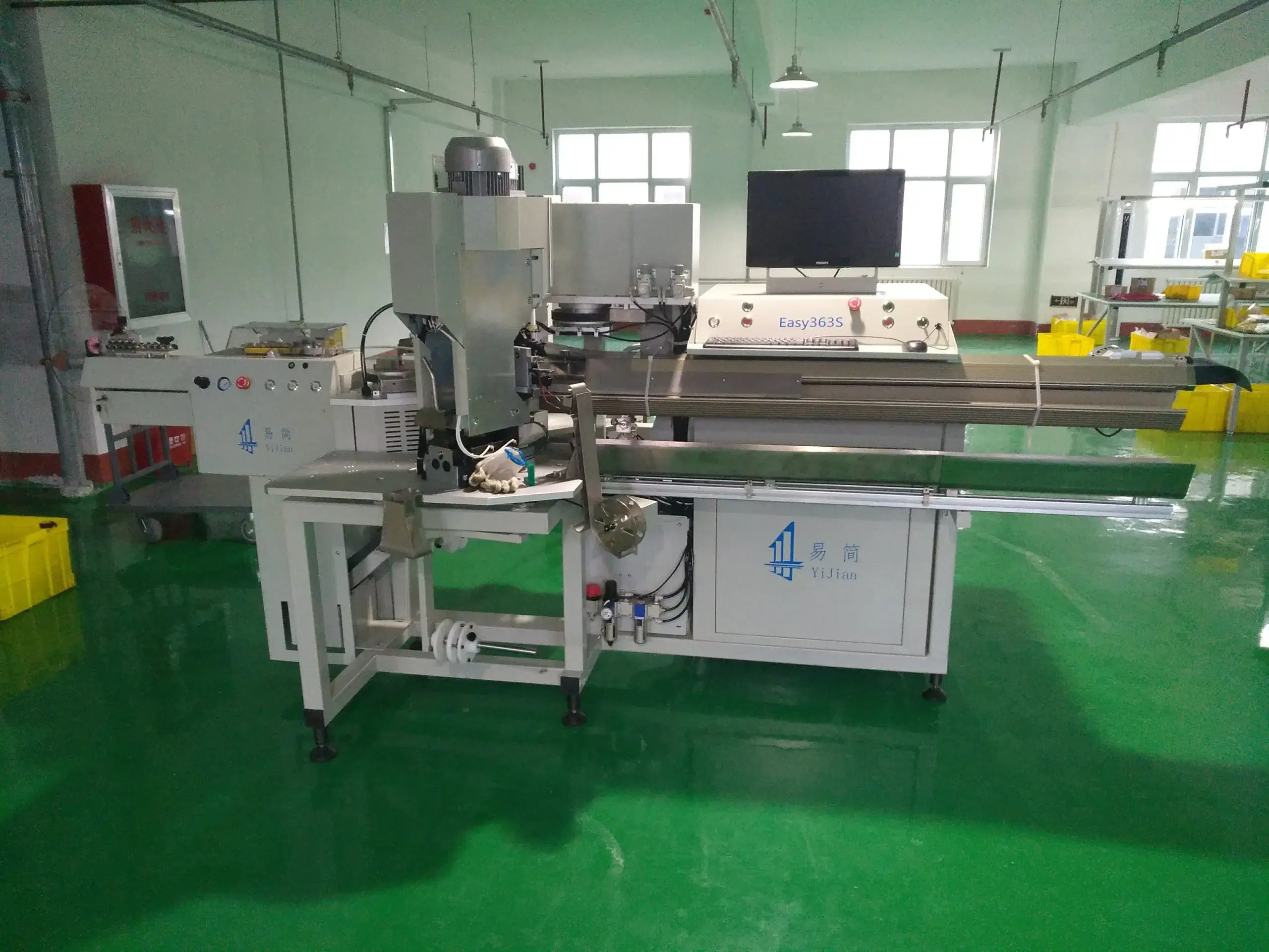
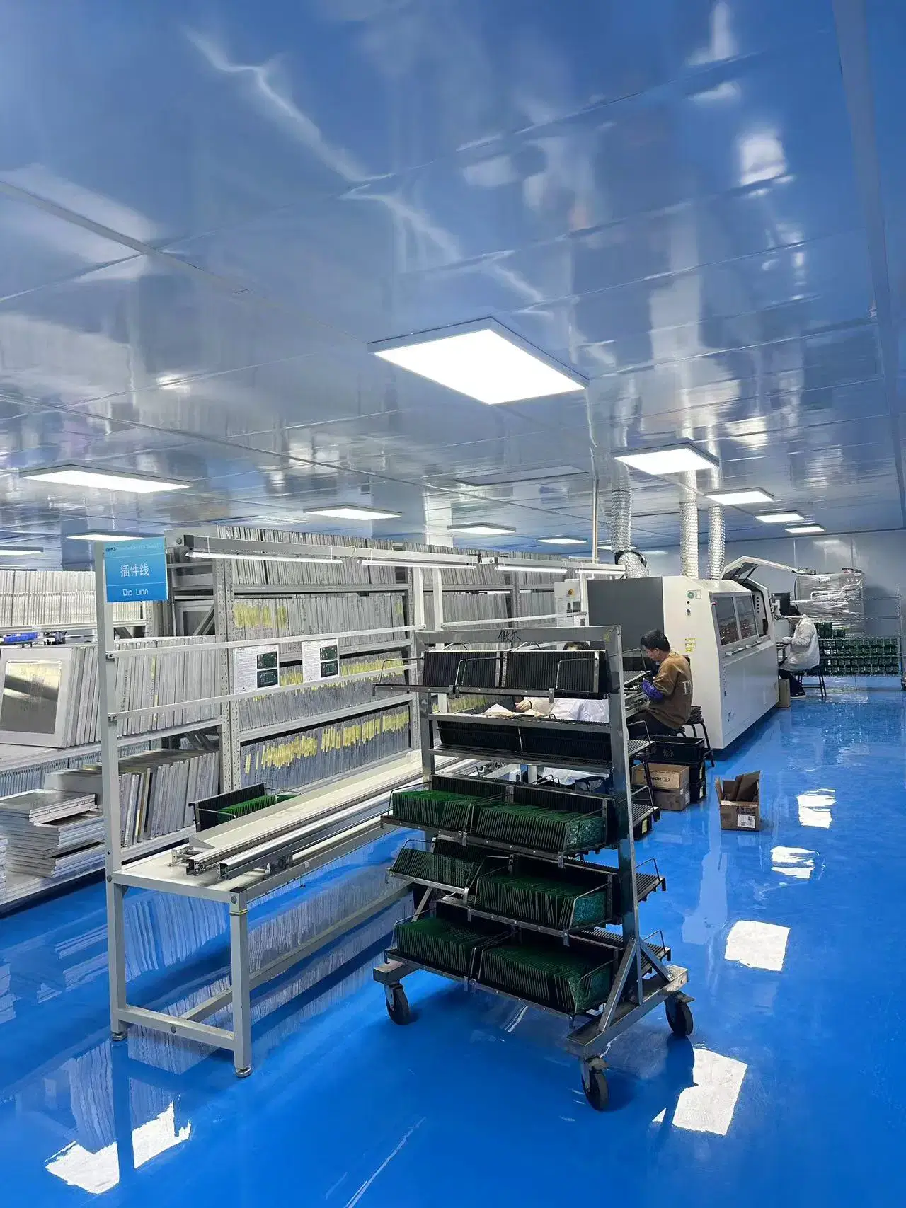
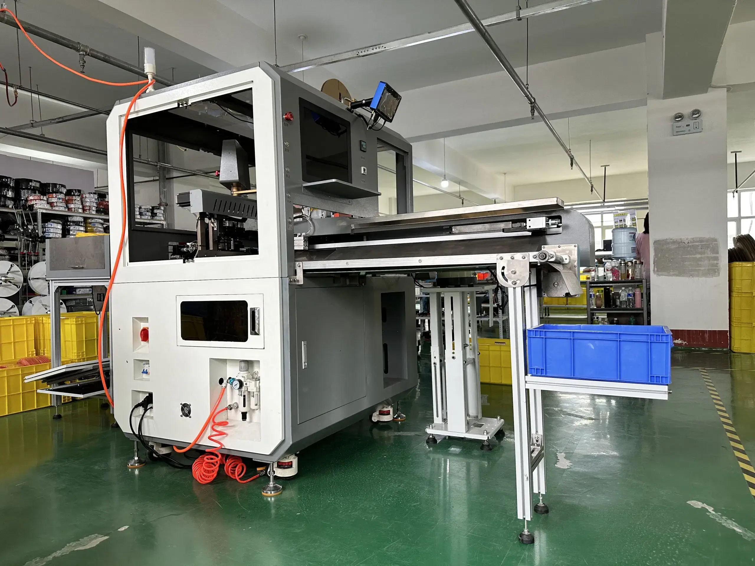
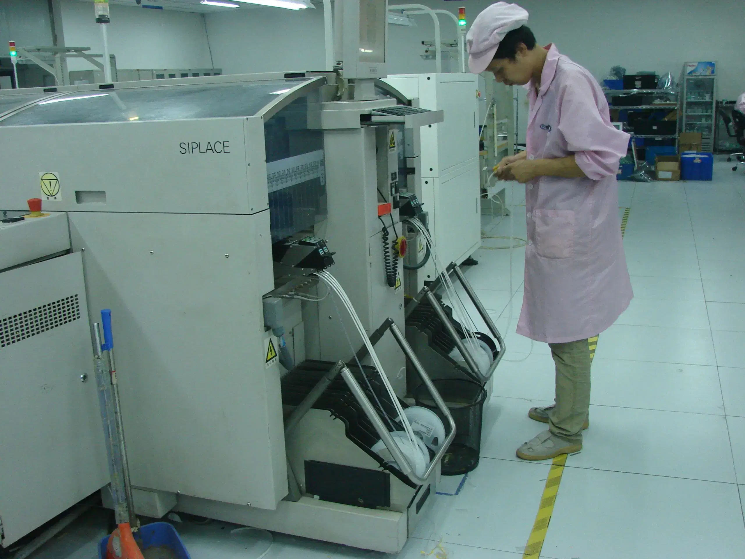
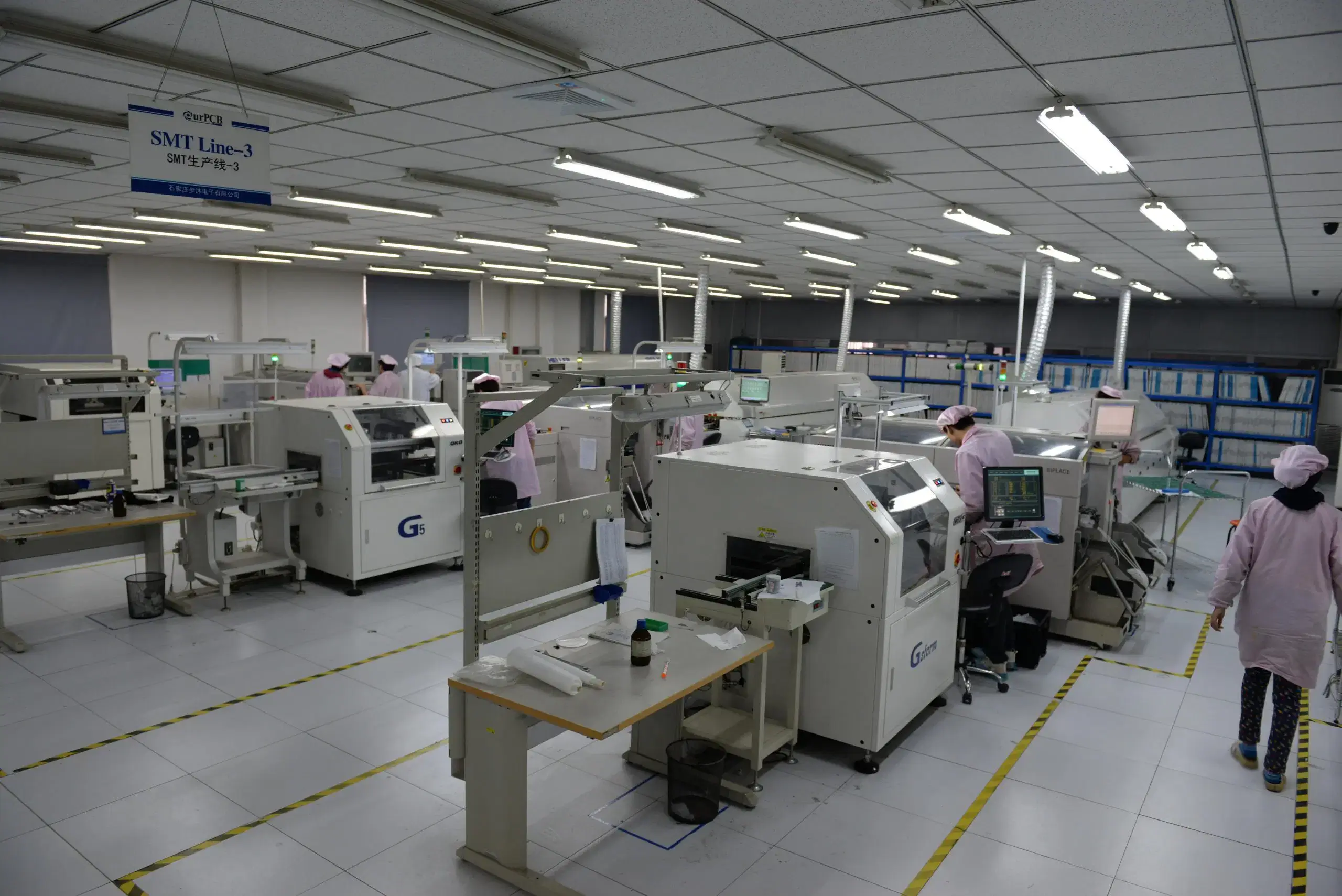
Our PCB Factory Gallery
Frequently Asked Questions
Yes. The BOM can be set up to assign ownership by line item while maintaining incoming inspection, shortage and excess responsibilities, authorized substitutes, lot identification, cost assumptions, and scheduling requirements under the same controlled BOM.
A synchronized file set typically consists of Gerber X2/Extended Gerber or ODB++, a BOM, centroid file, assembly drawing, a netlist when available, firmware, testing information, and packaging instructions. Any missing or conflicting revision within this file set may delay controlled production.
The authorization process for alternate parts involves engineering examination of electrical functionality, package, footprint, operating temperature range, lifecycle, source, and customer restrictions before the alternate part is approved. The approved alternate is then included in the controlled BOM revision and material records.
Yes, provided the fixture interface, software, acceptance and rejection limits, golden units where applicable, maintenance, ownership, and result correlation are defined.
Yes, provided the controlled instructions specify the firmware version, connector access, label placement, mechanical information, and pass/fail criteria.
Controlled rework is appropriate only after a defect receives an authorized engineering disposition and the board remains eligible for repair. IPC-7711/21D procedures apply to controlled rework, followed by post-rework inspection or testing to maintain batch-linked traceability.
The order must indicate which RoHS requirement applies to the specific assembly, and the BOM, PCB finish, solder, component information, exemption documentation, and target markets must be configured accordingly. One declaration does not automatically extend to all products or markets.
Current fabrication and assembly data, authorized alternates, stencils, machine programs, test plans, and prior deviations may be reused. Engineering first matches each asset to the current product version so an outdated setup does not enter the new batch.