Upload BOM & Gerber
-
Mobile: +86 13312967631
-
Email: sales@sugaintl.com

Full Turnkey PCB Assembly Services
One-Stop Full and Partial Turnkey PCBA Manufacturer in China
There is one place to get your boards built from your BOM through the entire process of PCB fabrication, sourcing, SMT/THT assembly, inspection, and testing. You keep design control over your boards while SUGA eliminates the separate vendor coordination.
3–5 DaysPrototype Assembly
10M Points/DaySMT Capacity (18 Lines)
01005Fine-Pitch Placement
IPC-A-610Workmanship Standard
What Is Turnkey PCB Assembly?
Turnkey PCB assembly is a managed service that takes your approved manufacturing data through to inspected and delivered PCB assemblies (PCBAs) through one supplier. Your design inputs — Gerber data, BOMs, CPLs, and assembly drawings — are turned into fabricated PCBs using sourced components, and then assembled using SMT/THT, inspected, tested, packaged, and delivered by one vendor.
Turnkey assembly shifts all coordination for manufactured boards onto SUGA. You maintain engineering judgment, BOM selection, approvals, and acceptance criteria. SUGA eliminates the need for multiple separate vendors that could break the build.

Multi-Vendor PCB Production Failure Points
The point of failure is not typically within any one vendor's process; it occurs at the point of handoff. A board could pass AOI at the assembly house and subsequently fail in the field because the copper thickness tolerance provided by the fabricator has not been checked against the assembler's reflow profile.
This cross-check needs to be done by the same team before fabrication, sourcing, and assembly split across teams. Turnkey service closes the gap between fabrication, sourcing, assembly, and testing because everything is part of one build record, reducing miscommunication and accountability gaps from three separate sign-offs.

Turnkey PCB Assembly Service Coverage
A turnkey PCB assembly service may include PCB fabrication, component sourcing, SMT/THT assembly, inspection, testing, packaging, and delivery. Exact coverage depends on the project files, approved BOM, substitution preferences, and test criteria.
For a simple PCB, the service may provide standard fabrication, normal sourcing, SMT placement, AOI, and delivery. For a dense PCB board, additional items may include fine-pitch placement setup, X-ray inspection, functional test preparation, or stricter sourcing controls.
The term turnkey PCBA is often used when discussing the assembled product at the PCB level, while box build or enclosure-level assembly is also related. The focus is primarily on the PCB-level turnkey service.
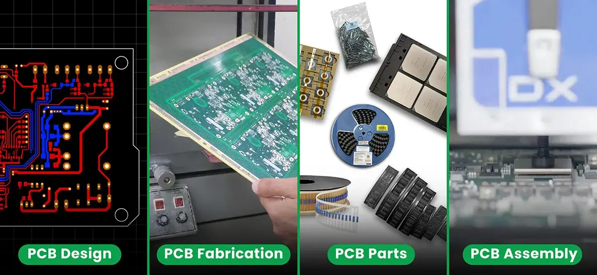
What Stays With the Customer?
As the customer, you should identify ownership of the BOM, who is purchasing the parts, how the boards are inspected, and what procedures are in place for the transition from prototype to production. These items ultimately determine the actual turnkey service and should be compared with the process provided by the supplier.
Items such as BOM choice, preferred AVL, substitute part approvals, firmware readiness, testing expectations, and acceptance criteria still define what constitutes a successful build. If a specific part must not be substituted, indicate this before procurement. If a functional test will rely on firmware, then the firmware and pass/fail criteria must be prepared before the test plan can be completed.
Full Turnkey vs. Partial Turnkey Assembly
The primary differences between full, partial, and consigned turnkey assembly are the responsibilities assigned to each party. Full turnkey service covers sourcing, BOM management, board fabrication, board assembly, testing, and shipment. Partial turnkey service might allow the customer to provide selected components while the supplier completes the rest of the sourcing and manufacturing process. Consigned assembly places most kit-accuracy responsibility on the customer.
The main decision in any turnkey assembly project is which organization will be responsible for controlling component sourcing.
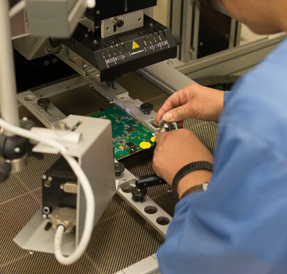
| Feature | Full turnkey | Partial turnkey | Consigned kit | Decision value |
|---|---|---|---|---|
| Component sourcing | SUGA handles all procurement | Customer supplies selected components; SUGA sources the rest | Customer provides the kit inventory | Choose based on who controls component availability and approved sourcing. |
| PCB fabrication | Managed by SUGA | Managed by SUGA | Depends on the agreed kit and board supply plan | Board source must match assembly, testing, and delivery needs. |
| Assembly services | Complete SMT, THT, or mixed assembly | Complete assembly still provided | Assembly depends on kit completeness | Assembly setup needs correct part identity, packaging, and overage. |
| BOM management | SUGA-managed | Shared responsibility | Customer-owned kit accuracy becomes central | BOM mismatch affects sourcing, placement, inspection, and delivery. |
| Inventory requirement | Minimal customer inventory | Customer may keep preferred or approved stock | Customer owns component availability | Inventory control protects approved parts but needs clean kit management. |
| Best suited for | Startups, OEMs, fully outsourced manufacturing | Buyers with existing stock or approved supplier relationships | Buyers with complete, controlled component kits | The best model follows sourcing control before price. |
Full Turnkey Model
The full turnkey model suits clients seeking a single supplier for the complete assembly process, from BOM through to tested boards. Before entering into a contract, request clarification of "SUGA manages sourcing" through a number of discussions and possible scenarios, such as: How does SUGA approve alternative parts when a component goes end-of-life during production? How frequently does SUGA provide clients with updates regarding sourcing? Can a locked AVL change without initiating a new approval process? The responses to these three inquiries will provide greater insight into a client's ability to rely on a full turnkey partner than their stated commitment to inventory ownership.
Partial Turnkey and Customer-Supplied Parts
The partial turnkey model is a collaborative sourcing arrangement whereby customers control some or all aspects of sourcing. This collaborative sourcing model enables customers to supply their own stock, inventory, or parts they specify, while SUGA manages the remaining sourcing, fabrication, assembly, testing, and shipping.
Customers are responsible for supplying clean manufacturer part numbers, package data, quantities, labels, packaging conditions, and overage quantities of the customer-supplied materials. An accurate part can still halt the assembly process if it is in an incorrect package. Similarly, if a kit does not contain sufficient overage to allow additional feeder setup or rework, assembly will also stop.
Partial turnkey arrangements work best when a customer has a specific need to maintain control over the selected parts, such as approved inventory or a relationship with a preferred supplier.
Turnkey or Consigned Kit
In a consigned assembly arrangement, responsibility for the component kit is transferred to the customer. The customer will provide a complete component kit for the assembly process to proceed based on the accuracy, labeling, packaging, and completeness of that kit.
The distinction between a turnkey and consigned PCB assembly is not a matter of cost; rather, it relates to who assumes responsibility for sourcing risk before placement starts.
If a customer has an established relationship with an approved supplier and wishes to maintain control over selected parts, then the partial turnkey model is appropriate. Conversely, if a customer desires a single supplier from BOM through to tested boards, then the full turnkey model may be appropriate. If a customer already possesses a complete verified component kit, then the consigned assembly model may be appropriate.
Turnkey PCB Manufacturing and Assembly Process
The production process flows through multiple stages beginning with an engineering file check, which verifies that the files are consistent with DFM/DFA standards, continuing through the PCB fabrication process, and sourcing of components, through to the assembly processes, both SMT and THT, followed by inspection/testing and the provision of visibility of the production process, and concluding with release, packaging, and shipment of the finished boards. Each stage provides distinct opportunities for control — even after the engineering file has been verified as correct, the boards must still clear every inspection, test, and release requirement before production is completed.

| Step | Required project data | SUGA coverage | Production output | Control value |
|---|---|---|---|---|
| Engineering file check | Gerber, BOM, CPL, assembly drawings | Review manufacturing, sourcing, placement, and assembly data before production | Usable manufacturing file set | Aligns fabrication, purchasing, placement, and inspection. |
| DFM and DFA analysis | PCB layout, stack-up intent, assembly data | Identify fabrication or assembly issues before manufacturing; 24-hour DFM feedback marker | Engineering comments | Catches spacing, pad, polarity, panelization, stencil, or soldering issues early. |
| PCB fabrication | Board specs, layer count, material, surface finish | Fabricate bare PCBs before assembly | Fabricated boards ready for placement | Confirms the bare boards are ready for assembly. |
| Component procurement | BOM, MPNs, approved alternates, AVL preference | Source components through approved or traceable channels | Components ready for SMT/THT assembly | Makes shortages, alternates, and lead times visible. |
| SMT and THT assembly | Placement data, polarity notes, component kits | Pick-and-place, solder paste printing, reflow, wave/selective or manual soldering | Assembled boards | Matches soldering sequence to board design. |
| Inspection and testing | Test expectations, fixture needs, firmware status, acceptance criteria | AOI, X-ray, ICT, FCT, functional or electrical testing by project need | Tested boards and issue findings | Matches testing to board risk. |
| Production visibility | Project stage, timing need, issue priority | Track production progress and communicate issue points | Stage progress and production notes | Keeps timing and issue points visible. |
| Final release, packaging, shipment | Delivery requirement, labeling rules, packaging preference | Pack and ship finished boards after final checks | Finished boards delivered | Aligns labels, packaging, final records, and delivery. |
Engineering File Check
The decision to proceed to production relies on the Gerber files, BOM, CPL, and assembly drawings. The Gerber files drive board fabrication, the BOM drives component procurement, the CPL tells pick-and-place machines where to place parts, and the assembly drawings help prevent polarity, orientation, and mechanical issues during assembly.
The file check identifies potential problems before component procurement and line setup. It can prevent delays that would occur if a package field is missing, polarity is unclear, or the information in the BOM and placement data does not match.
Where Do DFM Issues Surface?
DFM issues surface during fabrication; spacing, pad design, material selection, stack-up, panelization, and other fabrication-related concerns are included in DFM. DFA issues surface during assembly; component fit, stencil requirements, component polarity, component access, and soldering feasibility are included in DFA.
Although 24-hour DFM feedback matters, timely feedback lets designers resolve comments while the design can still change without triggering rework or schedule delay.
From Bare Board Fabrication to SMT/THT Assembly
A bare PCB fabrication run must include the appropriate stack-up, layer count, thickness, surface finish, and panelization. The board fabrication plan must also match the later SMT/THT assembly process. SMT devices are typically smaller than THT devices; a mixed PCB must have a soldering process that accommodates both methods. This helps production move smoothly into placement and soldering for all components involved.
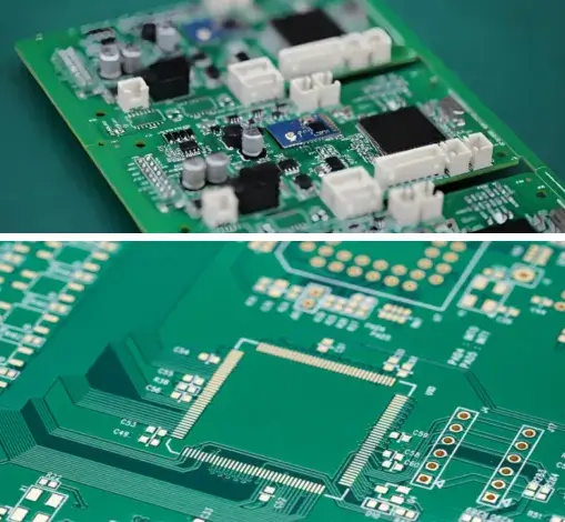
Final Release, Packaging, and Acceptance
Finished boards should agree with approved inspection results, expected test results, labeling requirements, packaging parameters, and acceptance criteria before release. Boards are protected from damage during shipment through packaging, while labels allow identification of the correct batch and project, and delivery notes provide a link between shipped boards, batch, project, and downstream build.
Component Sourcing and BOM Control
BOM control within turnkey PCB assembly connects component identity, traceable sourcing, availability verification, accepted alternates, MSL/ESD handling, package-level extra quantity, and procurement timing before assembly starts. A fast assembly schedule is only possible when the BOM information is sufficient and available.
| BOM control item | Risk level | Control value | Available evidence | Production impact |
|---|---|---|---|---|
| Authorized or traceable source check | High | Keeps component identity and sourcing traceability clear | DigiKey, Mouser, LCSC, Avnet | Reduces counterfeit, unapproved, or mismatched component risk. |
| BOM verification | High | Checks MPN, package, quantity, alternates, and completeness | BOM verification within 24 hours | Prevents sourcing or placement errors before procurement and assembly. |
| Availability check | High | Confirms whether BOM lines are ready to purchase or need alternates | Component availability / warehouse inventory | Keeps sourcing condition clear before SMT/THT scheduling. |
| Substitution approval | Medium | Matches alternates to electrical, package, lifecycle, and project requirements | Hard-to-source parts support | Keeps substitute decisions aligned with design intent. |
| MSL, ESD, packaging condition | Medium | Keeps ICs, BGAs, fine-pitch, and moisture-sensitive parts ready for assembly | MSL / ESD / package control | Prevents handling, storage, and reflow-related assembly defects. |
| Extra parts by package size | Medium | Provides enough overage for placement loss and setup needs | Package-size overage table | Improves assembly continuity for small packages and high-density boards. |
| Procurement timing | Medium | Separates sourcing time from assembly time | 2–8 weeks parts procurement | Long-lead components are planned before fast build schedules are set. |
How Is Component Authenticity Checked?
Controlled sourcing is the start of authenticating parts, but every component listed in the BOM must also be checked line by line. Each MPN, package, quantity, lifecycle status, approved alternate, and sourcing requirement on the BOM must correlate with the design intent of the finished product. If the BOM has an accurate MPN but the component is in the wrong package for assembly, the assembly line can stop.
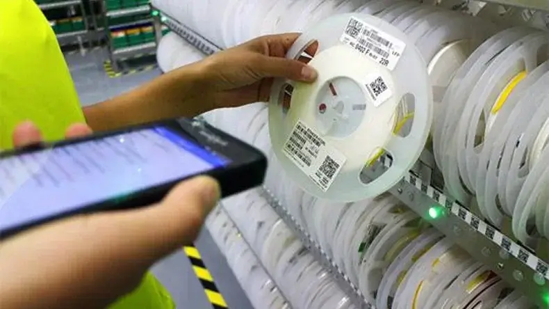
Component Availability Check
Component availability check for your BOM determines whether a fast turnkey build is feasible. You may have a technically accurate BOM, but it may still include long-lead, obsolete, imported, or shortage-prone component lines. SUGA verifies component availability before SMT/THT scheduling, eliminating confusion between sourcing time and assembly time.
Extra Parts by Package Size
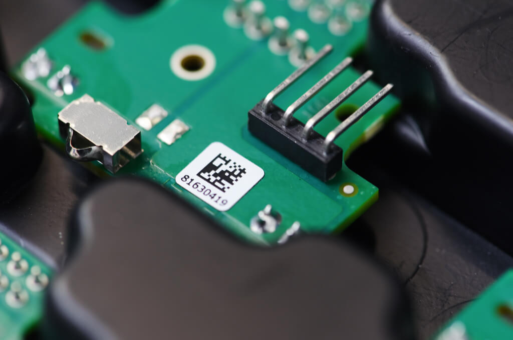
Small package sizes must have larger overage allowances than larger packages. The additional overage is required because feeder setup, placement loss, inspection burden, and rework reserve increase as package size falls.
| Component size | Required extra quantity | Why it matters |
|---|---|---|
| 1206 / 1008 / 0805 / 0804 / 0603 (standard passives) | 100 | A 100-piece overage covers initial setup loss and placement continuity during production. |
| 0402 | 250 | Smaller packages require more allowance for feeder wear, placement loss, and potential rework needs. |
| 0201 / 01005 / 008004 (ultra-fine pitch) | 500 | Ultra-fine and micro-package assemblies require a 500-piece overage for handling loss and the greater inspection burden. |
Overage is not meant to be a rounding buffer, especially for very small packages such as 01005 or 008004. A single feeder jam may halt a complete assembly line if there are not enough spare parts on hand to restart production, because there is no time to re-tape those parts mid-run.
How Are Hard-to-Source Parts Handled?
Shortage part management belongs in BOM control before assembly scheduling. Identify all unavailable parts, confirm approved alternates, check electrical and package compatibility for those alternates, and validate sourcing lead time.
PCB and Assembly Service Range
PCB and assembly range should be read as one manufacturing check. PCB assembly requires each PCB to match manufacturing design parameters, including layer count, PCB thickness, panel size, copper weight, line width, hole size, aspect ratio, impedance range, surface finish, SMT/THT assembly method, fine-pitch handling, BGA/QFN placement, and production capacity.
| Service area | SUGA service range | Where it matters |
|---|---|---|
| Layer count | 1–40 layers, delivered through in-house production | Dense routing, power boards, communication boards, complex multilayer PCBAs. |
| Finished board thickness | 0.2mm–10.0mm | Thin boards, thick boards, mechanically stressed boards, fixture-supported production. |
| Max panel size | 610mm × 1200mm | Large panels, oversized assemblies, batch panelization, high-throughput production. |
| Copper thickness | 0.5oz–12oz | Power electronics, thermal load, current-carrying designs, industrial and energy boards. |
| Min line width / spacing | 2.5mil / 2.5mil | High-density routing, compact layouts, fine trace designs. |
| Min finished hole | 0.1mm | Fine drilling, compact interconnects, dense vias, high-density board structures. |
| Max aspect ratio | 25:1 | Thick boards with small holes and advanced plating requirements. |
| Impedance tolerance | ±10% | Controlled impedance boards, communication equipment, signal-sensitive assemblies. |
| Surface finishes | HASL(LF), ENIG, Immersion Tin/Silver, Golden Finger, hard gold, OSP, ENEPIG | Solderability, shelf life, contact reliability, fine-pitch assembly. |
| Assembly types | SMT, THT, Mixed Technology | Boards combining compact SMT parts with connectors, relays, or terminals. |
| Fine-pitch assembly | 01005 placement with fine-pitch BGA and QFN | High-density PCBA, compact electronics, hidden-joint inspection. |
| SMT production capacity | 18 SMT lines, with a combined capacity of 10 million placement points per 24 hours | High placement-count boards, batch production, dense SMT projects. |
| Soldering process | Reflow, wave, selective/manual soldering for mixed assemblies | Boards with SMT + THT combination or process-sensitive components. |
Reading the Service Range Against Real Boards
If a design is near 40 layers with 12oz copper, it will require proper stack-up and thermal checks before fabrication because heavy copper affects heat transfer through a stack that already has routing constraints. In addition, a PCB that is approximately 610mm x 1200mm at greater thickness will need to be checked for panel handling and fixtures prior to the start of assembly; if not, the first panel could jam the conveyor.
The combination of small holes with a 25:1 aspect ratio creates a higher plating risk than either spec alone; the DFM check should flag this combination first.
SMT and THT Assembly
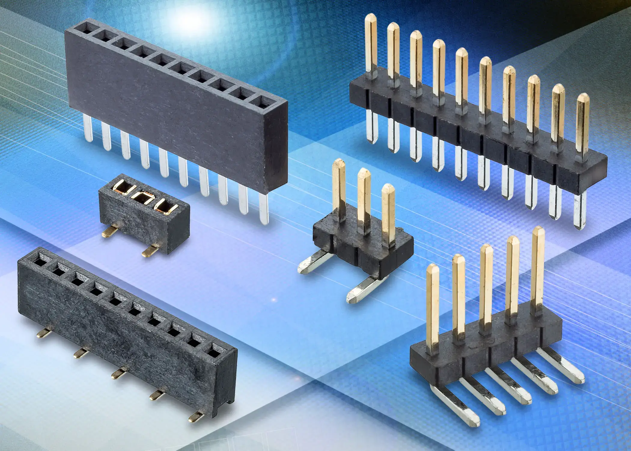
SMT supports compact component placement and fine pitch, while THT supports connectors, terminals, relays, and larger mechanical components that need through-hole strength. This mix of assembly technology requires a more detailed plan than a single assembly process, as the assembly sequence must protect previously placed parts and still allow for the proper assembly of through-hole components.
High-Density Assembly at 01005 and Below
All PCB assembly at 01005 or below will result in an increased level of risk for the assembly process, as an operator will no longer only place visible components on a PCB. Stencil control, solder paste characteristics, placement accuracy, and downstream X-ray inspection will have a higher level of importance as the package size decreases, as noted in the overage table above for sizes 0201, 01005, and 008004.
Surface Finish Choices
The choice of surface finish will greatly impact long-term solderability, shelf life, contact reliability, and connector interface of a PCB. The selection of the surface finish material should be made prior to fabrication because ENIG, hard gold, and OSP have varying shelf lives and rework ability once the PCB has left the factory.
Inspection and Testing Methods
AOI, visual inspection, X-ray inspection, ICT, FCT, functional testing, and electrical testing are all different methods of testing for quality assurance purposes; they cannot be interchanged. Each method is designed to catch a different type of defect; the mix of methods is dependent on the assembly, component package, test access to the assembly, firmware readiness for testing, and acceptance criteria.
| Test method | Quality control focus | Best use case |
|---|---|---|
| AOI | Missing parts, polarity issues, visible solder defects, solder bridges | SMT boards with visible joints and dense placement |
| Visual / microscopic inspection | Surface-level workmanship and obvious assembly defects | Boards needing manual confirmation at connectors or rework zones |
| X-ray | Hidden solder joints, BGA/QFN/CSP/uBGA risk, voiding and hidden bridges | BGA, uBGA, CSP, QFN, high-density assemblies |
| ICT | Electrical connectivity and component-level faults where test access exists | Boards with accessible test points and a suitable fixture path |
| FCT | Functional behavior against expected operation | Boards with defined functional acceptance criteria |
| Functional testing | Real-use or fixture-based board behavior | Boards requiring firmware, load, interface, sensor, or comms validation |
| 100% E-test / AOI / X-ray / ICT / FCT | Full production coverage across five inspection and test methods | Production boards with stronger production requirements |
Quality systems and acceptance standards behind this table: ISO9001 / IATF16949 / ISO13485; IPC-A-610 Class 2; RoHS.
AOI and X-Ray Catch Different Defects
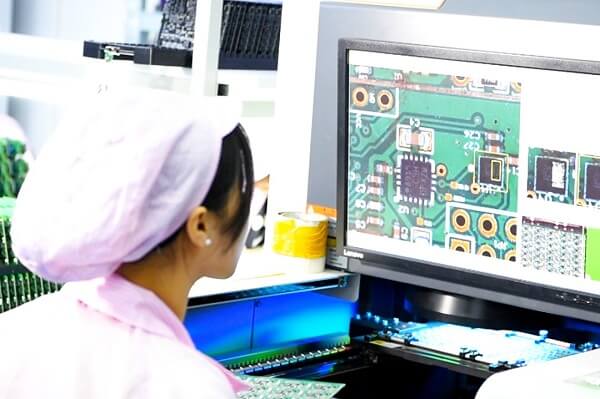
While AOI provides support for checking the placement of SMT parts that are missing, polarity issues, the existence of solder bridges, skew, and visible solder workmanship, AOI cannot provide inspections of the underside of package bodies, BGAs, uBGAs, CSPs, QFNs, and high-density assemblies. Voiding, bridging, and joint conditions exist that can only be seen on X-ray, so visual or microscopic inspection will continue to be required around connector locations and rework areas, where operators need to verify the surface condition prior to performing functional testing.
ICT, FCT, and Functional Testing
The test method sets the availability of test access, fixture setup, firmware readiness, and pass/fail criteria. If test point and fixture support are available, ICT will catch electrical faults at the component level. FCT checks if the boards function according to the expected performance. Functional testing depends on how the customer defined the functional test. A control board, sensor board, or power module may have specific firmware, load, interface, or signal requirements before the test has value.
Turnkey Prototype Assembly and Production
The speed of turnkey PCB assembly is based on component availability, clean BOM data, accurate placement information, testing requirements, and the stage of the project. A prototype is capable of moving quickly through the process when there are low test requirements and a stable BOM. Repeatable sourcing for production requires prepared inspection and clear acceptance criteria before starting the second production run. The same supplier can support multiple stages of a project, but the risk will vary at each stage.
| Project stage | Lead time | Quantity | Speed condition | Best use |
|---|---|---|---|---|
| Prototype assembly | 3–5 business days; 24-hour prototype marker | 1 piece | In-stock components, clean BOM, clear CPL, limited test requirement | Early hardware validation, MVP boards, engineering samples. |
| Standard turnkey / low-volume | 5–7 business days | 10+ pcs to small batches | Stable BOM, normal sourcing, defined inspection or test plan | Pilot builds, market validation, pre-production batches. |
| Production volume | 7–14 business days; 3–4 days mass production marker | 100+ pcs | Production setup, repeatable sourcing, prepared inspection | Repeat orders and production-ready turnkey runs. |
| Long-lead sourcing | 2–8 weeks parts procurement | Project-specific | Long-lead components planned separately from assembly time | Projects with imported, shortage-prone, or hard-to-source BOM lines. |
Prototype Lead Time
1 to 10 pc prototypes can utilize a fast turnkey service if the BOM is stable, placement data is clean, and the components are readily available. The 3 to 5 day time frame commonly slips because of component substitution issues that reviewers never flagged; if the BOM had a part that should not be substituted, the alternate part may be discovered only after it was put on the assembly line.
Low-Volume Production
In low-volume production, the BOM has developed, sourcing has stabilized, the assembly method has developed, and inspection requirements have started stabilizing. A prototype build indicates that an item can be manufactured as designed; a low-volume run indicates whether an item can repeat that manufacturing achievement with fewer surprises. Unexpected substitutions, excess parts, and ambiguous inspection requirements must be resolved before a subsequent low-volume production run.
Production Volume Requirements
Production volume is a different business decision compared to prototype speed; the approach to sourcing for 100+ pcs changes from "can we obtain this part" to "can we obtain this part in consistent quality on every individual batch." Before the 2nd production run, lock down 2nd source qualification, incoming inspection sampling rates, and documented acceptance criteria rather than reactively adjusting production volume to resolve defects.
When Does Urgency Change the Plan?
When looking at urgency, assumptions change regarding inventory, BOM readiness, testing requirements, rework tolerance levels, and inspection sequence. Fast builds can be accomplished if the components are available in stock, substitutes have been identified, and testing requirements are simple; but if you have a dense board, a heavily tested board, or a board with long-lead-time parts, you will need setup before building. The actual constraints should be identified before the requested delivery date.
Turnkey PCB Assembly Applications
Turnkey PCB assembly is used in projects where the sourcing, assembly, testing, and delivery of parts and assemblies must be coordinated. Each vertical has its own production risk before release.
Hardware Startup Launches
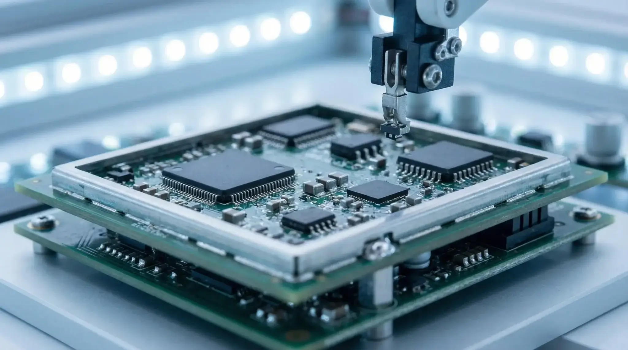
There are typically two separate project timelines associated with the startup of a hardware MVP company. First, MVP teams require sourcing both raw materials, such as fabricated PCBs, and components listed in the BOM to produce and deliver their products. Second, MVP teams must plan for the low-volume production of their products using SMT to assemble the components and conduct quality assurance inspections to ensure each part is ready for final assembly. Commonly recurring failures regarding MVP launches are the result of a substitution of a component at the time of functional testing that was not signed off prior to the build. The failure mode typically manifests itself as a change in either the electrical timing or footprint of the part, with the corresponding impact only occurring once the part is installed in the assembled product. While the actual substitution often appears to be inconsequential on the surface, in many cases a few cents, if the substitution was made without the authority of the design team, the result can lead to two weeks of downtime for the MVP production team to wait for an additional prototype build to be completed.
Medical Device Boards
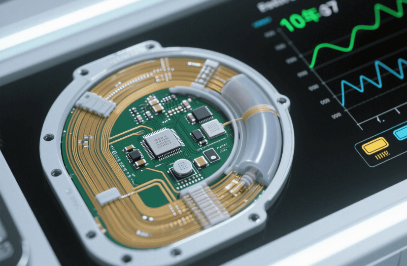
The sourcing and inspection of parts, the execution of a change-control process, and the ability to track the DHR under ISO 13485 compliance for medical control, monitoring, and diagnostic boards are needed to ensure that the board continues to maintain the same QA record as the original. Changes to the components of medical devices that would be routine for consumer devices may require complete quality assurance inspection and UDI-compliant labeling. Medical devices typically require acceptance criteria of IPC-A-610 Class 3, which is a higher degree of workmanship than the Class 2 baseline used elsewhere. A gap in DHR could cause a significant delay in the completion of a regulatory audit when compared to delays incurred by hardware rework.
IoT and Smart Device Boards
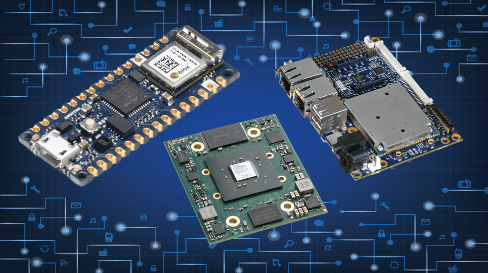
IoT and smart device boards require gateways, sensors, and compact wireless boards, which need both speed and stability in terms of supply chain management. The iteration speed for creating compact boards with fine-pitch BGA that was discussed in the previous section is one means of meeting the requirement for a reliable supply chain for the IoT and smart devices. The key challenge is getting the correct placement of components using advanced reflow technology and X-ray verification of the assembly when there is limited space on the compact board. If there is no room on the compact board for a second reflow pass, the assembly must be completed correctly the first time. There is no place on the compact board to put a hand-rework fix after the fact. Under BGA thermal pads on compact boards, X-ray void rates are generally targeted at approximately 25% based on IPC-J-STD-001 standards, but if the target is relaxed to reduce costs, the resulting intermittent connection failures will often occur in the field instead of in the laboratory.
Industrial Control Boards
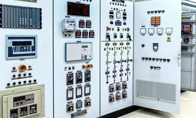
Industrial control boards, including controllers for electric motors, motor drives, relay boards, and field electronics, typically consist of a combination of SMT ICs paired with THT connectors and relays. This mixed assembly approach is a significant reason why proper assembly sequence is critical on these products. While the primary ICs are not generally considered the main area of risk during the field-service life of the product, it is the connectors, relays, and terminal blocks that have a higher level of risk. THT solder joints under mechanical stress can typically experience fatigue failure in the 3–5 year range, well after the initial AOI process has cleared the unit on day one. Any inspection process for connectors and relay joints should be separate from the AOI process as it relates to the pass/fail criteria.

Automotive Control and ADAS Boards
Automotive control system and ADAS-related boards require a reliable source of supply, records of inspection of mixed assembly, and evidence of sourcing under the requirements of IATF 16949. This generally includes the requirement for submission of PPAP documents and the use of AEC-Q100/Q200 qualified components as a precondition of approval for the BOM of a component. Most PPAP submissions are rejected for the absence of a qualification record related to each of the components.
Communication Equipment
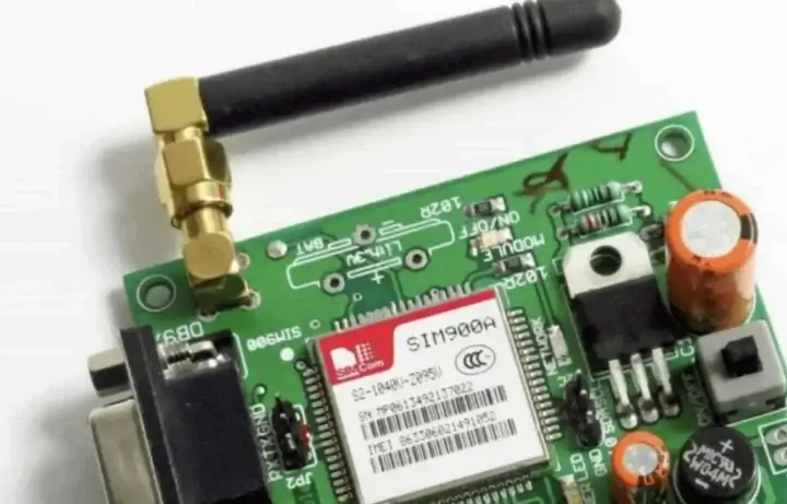
Long-haul and short-range communication devices, including routers, transmitters, and connectivity devices, require that the controlled-impedance tolerance is uniformly applied according to the service range table, ±10%; that connector placement accuracy and surface finish options are established prior to production; and that any drift in impedance which cannot be measured on a bench meter is measured by the amount of intermittent signal loss at the receiver in the field after installation. Measurements of drift outside of ±10% are not identifiable on the bench meter, but by the time the customer receives a board and starts to use it, they may have a measurable increase in the bit-error rates of the signal at the receiver.

Consumer Electronics and Wearables
Wearable and compact connected devices require speed of development, cost-sensitive sourcing of components, high-precision, low-pitch component placement as described previously, and aesthetic and packaging limitations that do not apply to industrial products. The issue of substituting BOM items based on cost after tooling is closed becomes troublesome since a less expensive passive can be substituted for the BOM and can pass through 100% AOI while still shifting the thermal or cosmetic tolerance of a circuit board within an acceptable range, just a few percent shift. There is enough margin that ensures it clears the inspection, even though it may fail a drop test or cosmetic QC check downstream.

Renewable Energy and Power Electronics Boards
Heavy copper handling, up to 12oz, and thermal-aware manufacturing are two concerns that need to be addressed for all boards related to solar micro-inverters, BMSs, and power module circuitry. As there are many different types of power components sourced with long lead times, the heavy copper handling in the service range table should be aligned with these components. In general, grid-tied designs require that UL1741 or IEC 62109 certifications be provided with the BOM. Under BGA thermal pads, X-ray void-rate checks will replace visual pass results provided by AOI. X-ray reviews of power modules will frequently flag void rates exceeding 25–30% under thermal pads for rework since thermal voids are usually where the first failures are found in grid-tied inverters.
Frequently Asked Questions
Yes. All Gerber files, BOMs, CPLs, drawings, and test notes will be treated as protected project manufacturing data under NDA. Only the engineering, sourcing, production, and quality teams directly involved in the build process will have access to this information.
A credible turnkey PCB assembly provider will have full control of PCB fabrication, component sourcing, SMT/THT assembly, inspection/testing, and delivery. Evidence of this is based on three checkable signals: (1) the supplier's production and inspection records, (2) the supplier's ability to issue a DFM report before production, and (3) the supplier's ability to provide documentation demonstrating traceable sourcing, such as authorized distributor records.
Yes, the turnkey assembler will provide conformal coating whenever the application requires moisture, dust, corrosion, or other environmental protection. A coating plan should define coating type, areas to mask, keep-out zones, connector protection, inspection method, and whether testing occurs before or after coating.
Once proper packaging, destination, documentation, and shipping method have been prepared during the same turnkey shipping step, finished assemblies can be shipped internationally, since export documentation is prepared along with the packaging and labeling before the assembled boards are packaged.
The primary disadvantages of turnkey PCB assembly are reduced direct control over component purchases, greater reliance on the supplier's communication, potential substitution of components, and the schedule impact of long-lead components. These factors can be controlled through BOM approval, component sourcing documentation, full or partial model selection, and adequate inspection requirements.
The minimum set of required files for turnkey PCB assembly are Gerber files, BOM, CPL, and assembly drawings. If the assembly process requires functional testing, include test fixture information and any associated test documentation. If the end-use of the PCB will require conformal coating to provide environmental protection, it should be noted in the assembly drawings. If the delivery of the PCBs will have any label or packaging requirements, they should be included. Also, when functional tests depend on firmware, the associated pass/fail criteria should be clearly defined before developing the test plan.