Upload BOM & Gerber
-
Mobile: +86 13312967631
-
Email: sales@sugaintl.com

High-Volume PCB Assembly Services
High-volume printed circuit board assembly manufacturer from China
High-volume PCB assembly uses a production program controlled by SUGA to coordinate PCB fabrication, component procurement, and SMT assembly. SUGA also coordinates THT assembly, mixed assembly, in-process inspection, electrical testing, FCT, and repeat-order control during high-volume repeat production.
Up to 60,000 CPH
±30 µm at 3σ Placement Capability
0201 to Large BGA/LGA
IPC-A-610J Control
J-STD-001J Soldering
Full Lot Traceability
What Is High-Volume PCB Assembly?
Since there is no single volume threshold for high-volume PCB assembly , it is better understood as a repeat-production model from NPI through recurring production. Stable designs, controlled BOMs, appropriate production-line loading, and reliable inspection processes allow high-volume automation and testing to operate consistently across repeated PCB production runs. High-volume PCB assembly can be distinguished from a single large PCB order that may still contain unresolved manufacturing or supply risks.
| Production pattern | Quantity signal | Production characteristic | Production guidance |
|---|---|---|---|
| Early production-scale PCBA | Around 1,000 assemblies or a recurring order program | Automation begins to provide value, but design changes and test readiness may still limit repeatability | Treat quantity as an early scale signal; confirm design, BOM and test stability before assigning a high-volume production plan. |
| High-volume PCB assembly | Around 5,000 assemblies or stable repeat demand | Material use, placement programs, inspection and testing can be standardized across repeat runs | Use when design revisions and approved parts are controlled enough to protect line efficiency. |
| Sustained large-volume production | 10,000+ assemblies or long repeat runs | Setup, tooling and fixture investment can be amortized across sustained output | Relevant when supply continuity, line capacity and release testing support recurring production. |
| High-mix low-volume assembly | No high-volume threshold | Frequent product changes, smaller lots and repeated setup changes | Use a frequent-change scheduling strategy instead of forcing high-volume economics. |
Volume Thresholds
A recurring order of 5,000 stable boards may justify repeat tooling and scheduled line capacity, matching the high-volume threshold above, while a one-time order of 10,000 boards with an unfrozen BOM may not be ready for sustained production regardless of quantity. A 1,000-board program still sits in early production-scale territory: automation begins to add value, but design and test stability, not order size, decide whether it can graduate to a high-volume plan.
When the design is still moving, higher output magnifies footprint errors, substitutions, and incomplete test logic. The useful threshold is therefore not quantity alone, but whether the same controlled setup can run again without new tooling, programs, or test qualification.
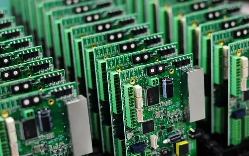
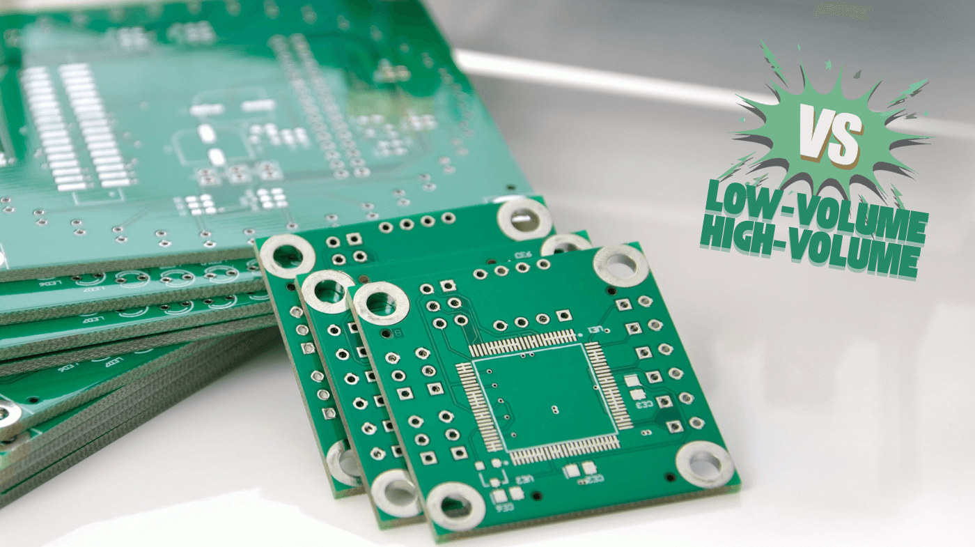
High-Volume vs. Low-Volume Assembly
High-volume PCB assembly and low-volume PCB assembly require different production processes and procedures. For example, a PCB manufacturer can automate the assembly of a single PCB design using the same tooling and approved components used to assemble hundreds of boards. As such, an automated assembly process for high-volume PCBs reduces the unit cost of the assembled PCB while also allowing for a more streamlined manufacturing process.
Similarly, producing PCBs for the low-volume assembly market creates added costs because tooling and production setups must be changed more frequently during the production process. The assembly process also has to be set up differently to accommodate the multiple PCB products being produced.
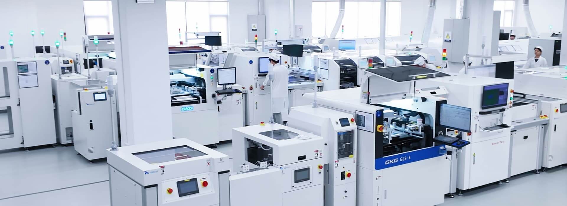
Production Capacity and Assembly Limits
PCB assemblies can be produced using both high-volume and low-volume production methods. Many PCB manufacturers combine SMT and THT technologies because the two technologies are often used in the same assembly. For example, SMT components can be combined with THT components or connectors to produce mixed-technology PCB assemblies.
The main high-volume PCBA assembly types are SMT, THT, mixed technology, and single- or double-sided assembly. The right high-volume PCB assembly production plan uses line capacity, placements per board, package geometry, panel dimensions, board construction, thermal mass, inspection access, and downstream test takt time.
Bare-PCB construction matters because copper weight, board thickness, surface finish, and panel format change thermal loading, handling, and solder-profile requirements before placement begins.
| Capability | Supported range or process | Manufacturing response |
|---|---|---|
| Placement throughput | Up to 60,000 components per hour | Convert CPH into board-level capacity using placements per board, panel count, usable machine rate, changeovers and downstream inspection/test takt time. |
| Placement accuracy | Down to ±30 µm at 3σ | Supports fine-pitch placement and repeatable component positioning. |
| Assembly types | SMT, THT, mixed technology, single-sided and double-sided assembly | Keep every soldering stage under one controlled production program. |
| Mixed assembly | Double-sided SMT/PTH, BGA on both sides, wave and selective soldering routes | Account for thermal sequence, bottom-side component clearance, fixture access and localized heat exposure through final inspection. |
| PCB size | 50 × 50 mm to 610 × 508 mm | Match panel, conveyor, tooling and fixture capacity to the full board dimensions. |
| PCB thickness | 0.5–4.5 mm | Match board rigidity, warpage risk and thermal mass to handling and solder-profile controls. |
| Small component support | 0201 passives | Link small-component placement to pad design, stencil aperture, SPI/AOI coverage and feeder stability. |
| Fine-pitch package support | Fine-pitch QFP, DFN, BGA, micro BGA, VFBGA and LGA; FPGA devices in supported BGA/LGA packages | Use package geometry, pad design and assembly access to set the process. |
| BGA geometry | Ball diameter down to 0.2 mm and BGA pitch down to 0.35 mm | Use package drawing, stencil, reflow and X-ray controls for 0.35 mm-pitch BGA assembly. |
| Large components | Large BGA/LGA, high-pin-count connectors and terminals | Match placement range, mechanical support, solder volume and inspection access to the complete package mix. |
| Stencil process | Laser-cut stainless-steel stencils; screen or controlled paste-printing route | Connect aperture design, paste release and cleaning control to repeatability rather than treating stencil type as a standalone quality claim. |
| Solder process | Leaded and lead-free reflow, wave and selective soldering | Match alloy and thermal profile to the board construction and component mix. |
| Board type | Rigid, flex and rigid-flex | Define fixture, support, handling and bend-area restrictions for each construction. |
| Board shape | Rectangular, circular, slotted, cut-out and other non-standard shapes | Set panelization, rails, fiducials, support points and depanelization during production setup. |
| Inspection access | SPI, AOI, X-ray and microscope inspection up to 20X | Assign each method by defect class. |
| PCB fabrication compatibility | 3 mil line/space routing; 0.5–5 oz copper; common surface finishes | These PCB inputs define thermal mass, solderability and assembly-profile requirements. |
| Manufacturing data | Controlled BOM, Gerber RS-274X, centroid/pick-and-place data and controlled changes | Maintain one controlled data baseline across repeat production. |
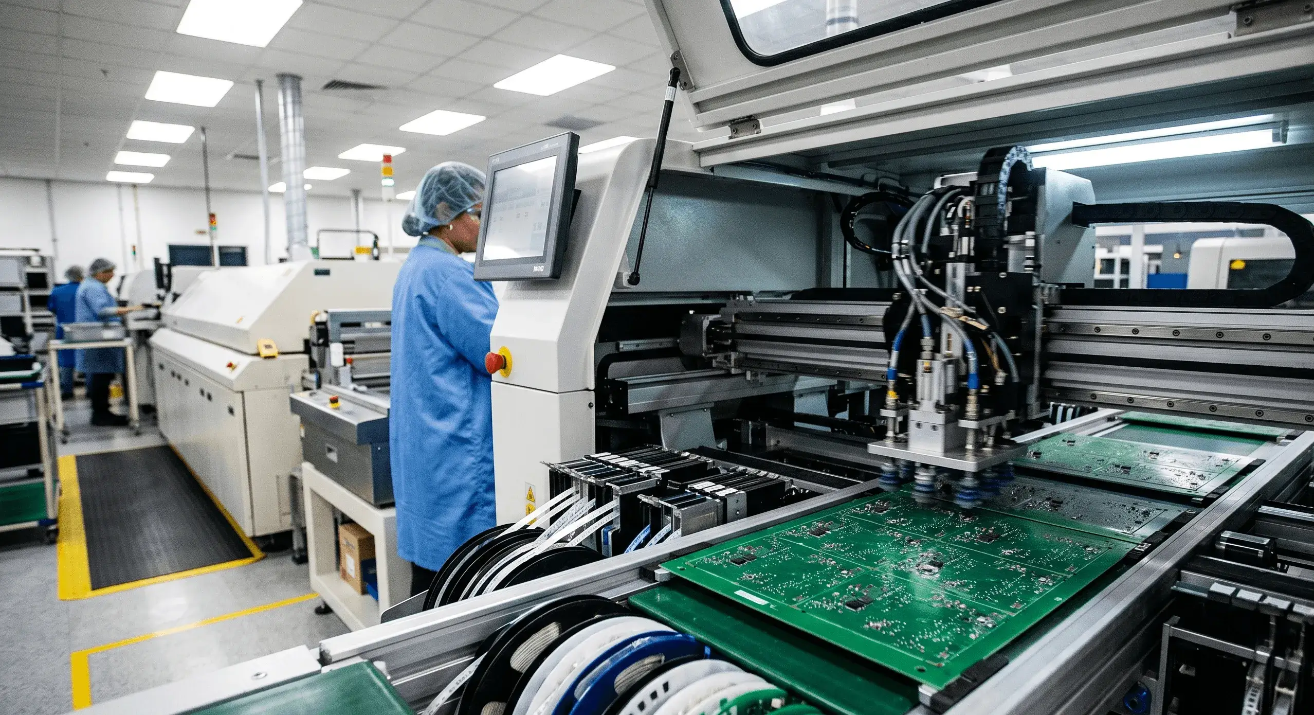
Automated SMT Placement
The nominal CPH is how fast a piece of equipment can work under optimum conditions; however, actual throughput values decrease as the number of placements per board increases. There is also a loss in productivity due to double-sided loading, panel layout, feeder replenishment, initial production sample approval, and changeovers. Since the downtime varies based on the specific needs of the product, if you were evaluating a 60,000 CPH machine specification, you would want to ask your supplier to convert the nominal CPH into a board-level output number for the specific package configuration and panel layout being quoted. You cannot base your expected delivery time on just the nameplate figure. Also, the true production takt time is typically governed by AOI, X-ray, THT, selective soldering, ICT, or FCT processes, even though the placement machine has remaining production capacity.
For very dense packages, placement capability is just one aspect of repeatability. Factors such as package drawings, stencil designs, reflow profiles, and X-ray inspections support the hidden-joint process. For example, when placing 0201 passives, factors such as pad geometry, paste release, SPI coverage, and feeder stability control placement repeatability.
Mixed-Technology Assembly
Most SMT placement equipment places SMT components, while THT assembly includes connectors, terminals, transformers, and components that require mechanical strength. Mixed-technology boards combine both processes on a single board. When referencing “single-sided” or “double-sided,” the terms describe the position of the components rather than a complete soldering plan.
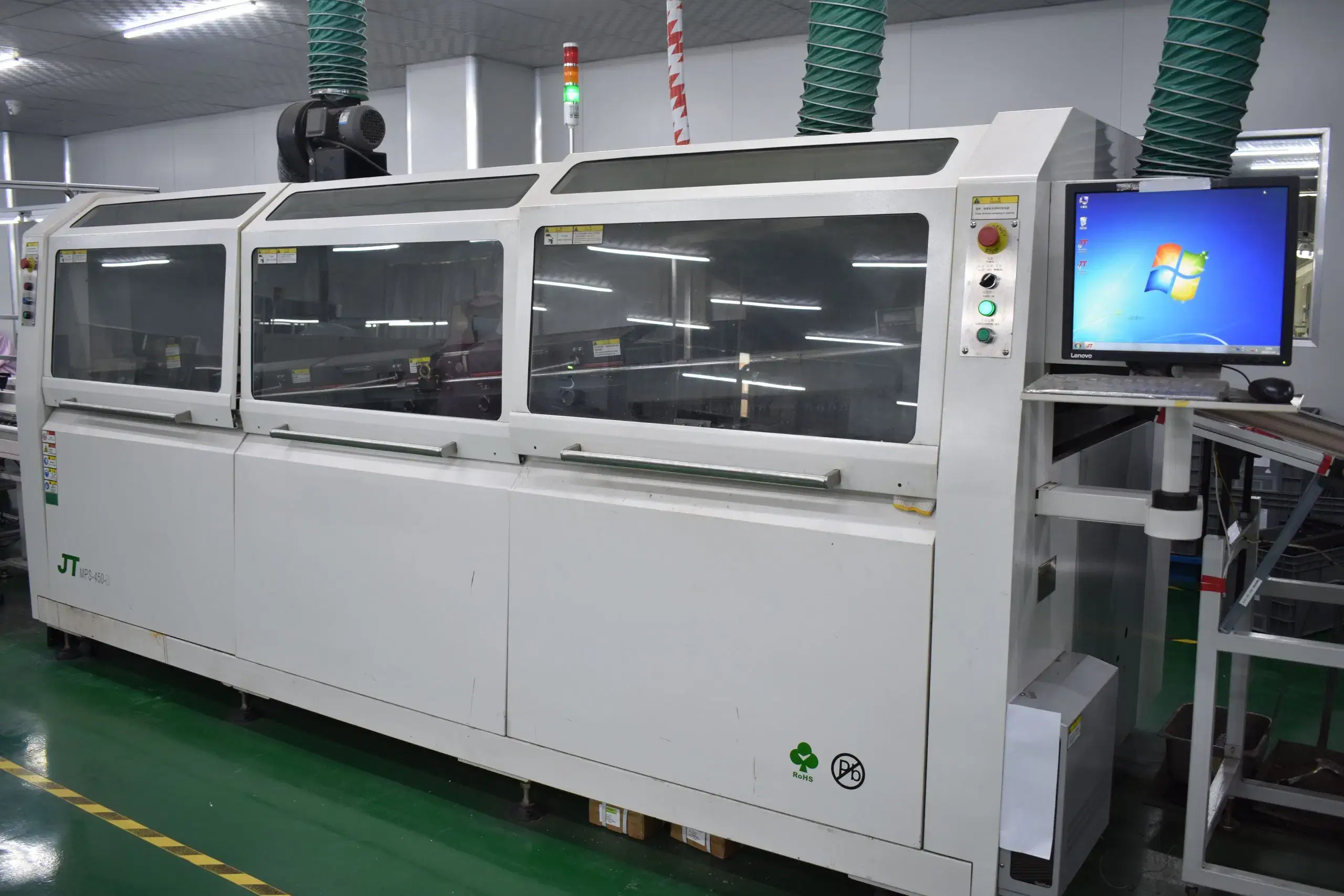
Wave soldering works for consistent PTH layouts that can pass through a controlled process; selective soldering is used to heat specific joints when bottom-side SMT, component thermal sensitivity, or clearance restrictions do not allow wave soldering of the complete assembly. Hand soldering is reserved for special positions or repair work. Generally speaking, hand soldering is not the main production method for high-volume electronic PCB assemblies.
High-Volume PCB Assembly Process
The production of PCBs in a high-volume production environment begins with a clearly defined set of processes for controlling the design, BOM, tooling, fixtures, and test plans.
Establishing the Production Baseline
The production baseline commences before the receipt of materials. The DFM, DFA, and DFT processes focus on the following key areas: footprints, polarity, panel types, fiducials, thermal issues, and accessible test-point locations. Additionally, the BOM identifies specified parts along with defined substitution procedures. The pilot build or first article provides an opportunity to evaluate the stencil, solder profile, fixtures, test program, and test logic before mass production.
From these processes, a controlled production baseline is created. A golden sample allows comparison of the manufactured product against the preset assembly specifications. Any changes to the design, BOM, program, or test must go through the controlled change process before incorporation into the production line.
Incoming Material Inspection
Verification of incoming materials includes checking the part number, manufacturer, package, quantity, and condition before the component enters assembly. Any components that are moisture-sensitive or require controlled storage will be handled according to established procedures and documented with the appropriate lot records. The bare PCB will be examined against the applicable drawing and finish, including PCB electrical testing, impedance verification, solderability testing, microsectioning, and thermal or construction checks required for the board.
If any components are considered substitutes and are not included in the controlled BOM, these components will be isolated until engineering and material controls approve their disposition.
Solder Paste Printing and Placement
The storage, condition, and working life of solder paste directly correlate with print consistency. Stencil aperture design and cleaning frequency control how consistently the solder paste is applied throughout a long run.
All feeders, nozzles, program revisions, and polarity data must be consistent with the controlled baseline before proceeding with component placement. SPI and first-article inspections detect print or position drift at the earliest possible time. Further inspection and testing verify solder-joint integrity and product function.
Reflow and Through-Hole Soldering
The solder profile of a soldering process must correspond to the PCB thickness, copper weight, component thermal mass, paste system, and alloy. A mixed assembly may go through a second reflow operation before PTH insertion, wave soldering, or selective soldering. The PCB’s bottom-side clearance and local heat exposure determine the soldering sequence.
The soldering sequence for a board assembly is determined by which components must survive the next thermal exposure and which joints require localized heat. Manual soldering may be approved for special applications; such soldering will require inspection and rework records.
Shipment and Nonconformance Control
A failed PCBA must be removed from normal material flow. The work order, lot number, or serial record identifies the failure, diagnosis, authorized rework or repair, and affected inspections or tests. After any rework or repair, the board repeats the relevant AOI, X-ray, ICT, FCT, or electrical testing.
Inspection and Testing at Scale
At the high-volume level of production, PCBA testing relies on a layered control system. The test plan identifies each defect class at the earliest practical opportunity for inspection or testing. Electrical testing and FCT then address defects that cannot be captured by visual inspection alone. No single inspection or testing method provides proof of complete product quality.
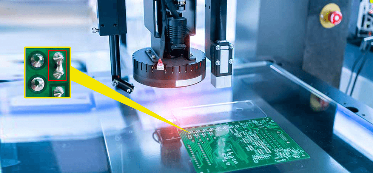
Which Inspection Method Fits Each Defect?
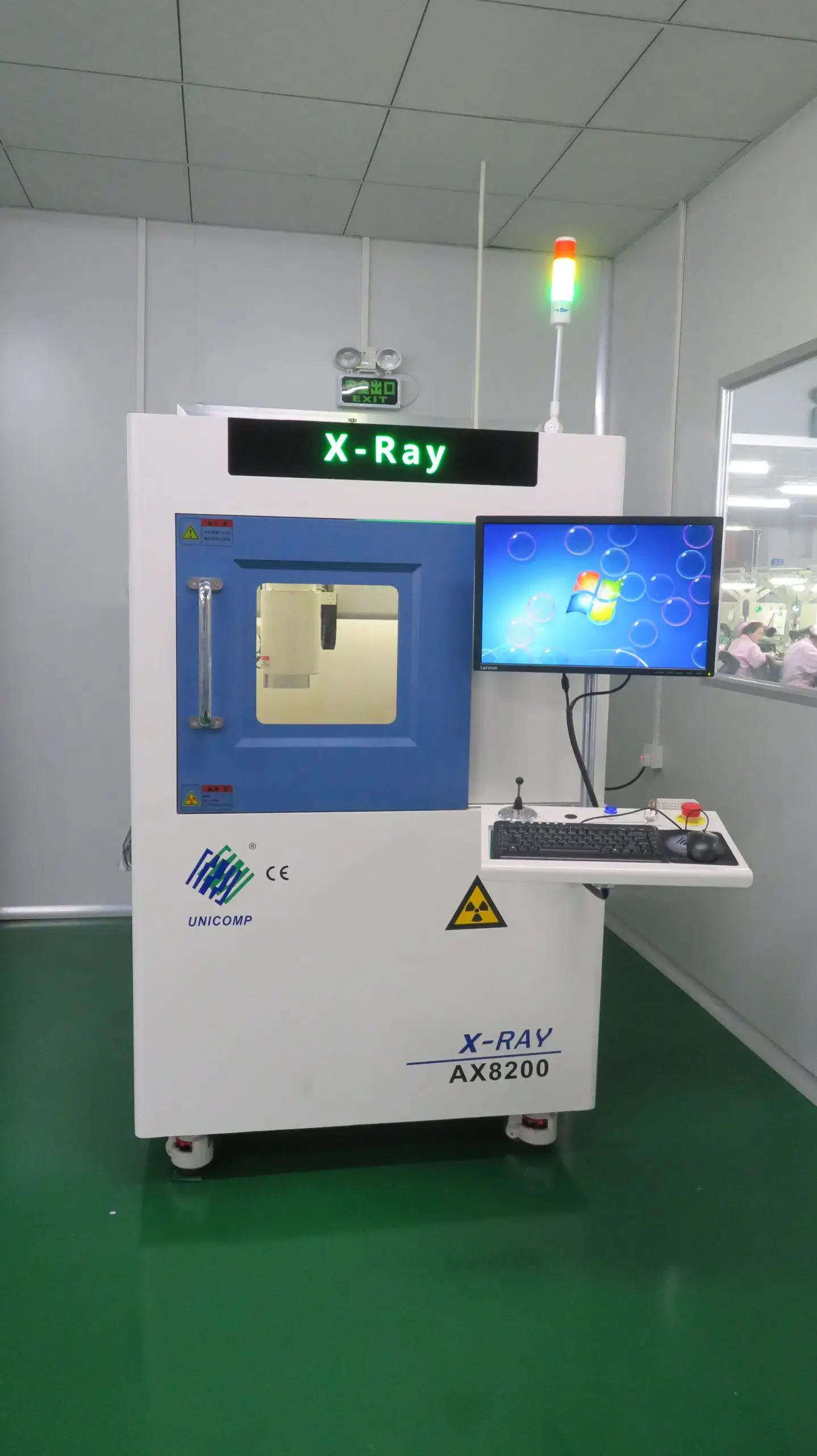
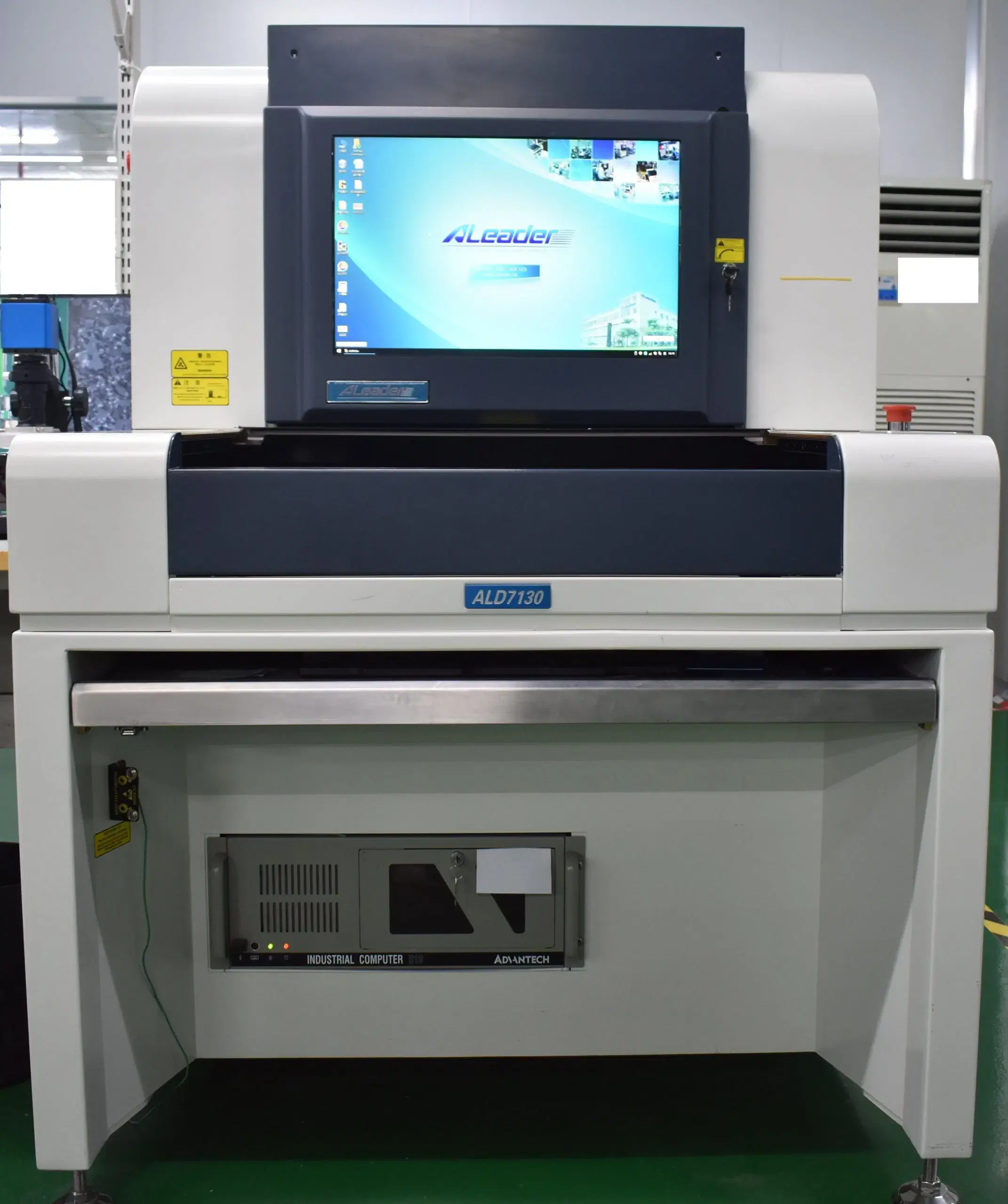
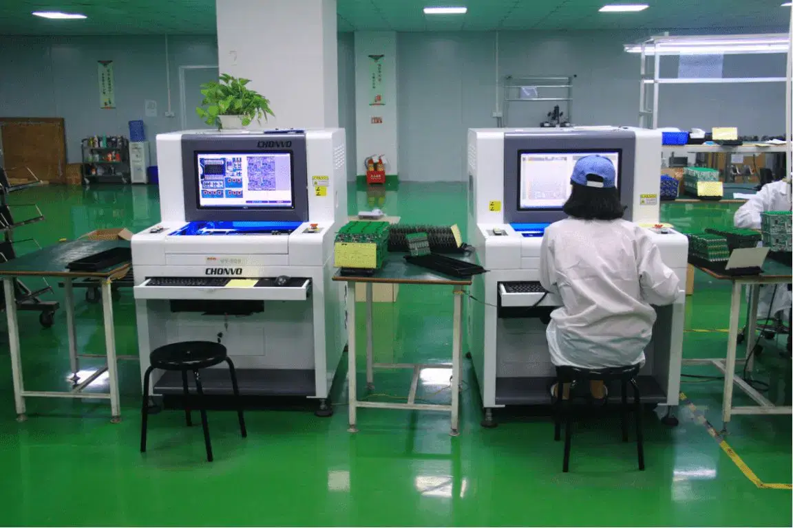
SPI provides a pre-reflow measurement of solder paste volume, height, position, and printing consistency before placement and reflow. AOI screens for component presence, polarity, placement, and visible solder conditions at normal assembly-line speeds. X-ray technology provides visibility into hidden BGA and LGA connections, solder distribution, and selected voids or bridges under BGA, LGA, QFN, and DFN packages. The level of coverage is determined by package geometry, assembly defect risk, defined defect rules, and the selected sampling or screening strategy.
When Does ICT Justify a Fixture?
The value of using ICT is maximized when the design enables test access and repeat demand can support fixture and program development. Compared with flying-probe testing, ICT provides faster screening of opens, shorts, and selected component or net conditions for a stable high-volume production run.
An economic decision must be made to determine whether to invest in fixture development or use repeated flying-probe testing. Flying-probe testing does not require a dedicated high-volume fixture and can verify continuity and selected components or nets, making it useful for pilot runs and products with changing test access. Stable repeat demand favors ICT, while FCT remains responsible for testing product behavior.
Functional Test Coverage
FCT coverage is based on observing the behavior of the product when tested against customer acceptance criteria. Items that are typically checked include power-up and power-down current draw, digital or analog product interfaces, I/O, sensor inputs and outputs, actuator inputs and outputs, communication, control, polarity, protection, and specified load response.
FCT plans may include interfaces specified by customers as part of their limit-testing requirements, including Ethernet, CAN, UART, USB, or wireless communication, when referenced in the FCT plan. It is important that all results are linked to the lot number or serial number for traceable programs and that, when there is a functional failure, diagnostic test results assist in isolating or identifying the root cause of the failure.
Lot Traceability
Lot traceability connects PCB and critical component lots, the work order, controlled BOM, program revision, process records, inspection and testing results, rework authorization, retesting, and shipment identity. When a defect recurs after production has been completed, these links help define the containment boundary and support RCA.
The granularity of lot traceability is primarily a function of product risk and order specifications. For instance, some PCB projects may not require serial number tracking at the board level; however, all programs must have the necessary documentation in place to allow for the effective reconstruction of production affected by a defect.
Cost and Lead-Time Drivers
Higher-volume orders lead to a lower cost per unit when the design, BOM, and production program remain unchanged. The proper basis for comparison is the total cost for each accepted board, since many factors affect the total cost per board, including material readiness, time spent on changeovers, fixture development, test coverage, yield, and additional rework or retest costs.
| Driver | Cost effect | Lead-time effect | Practical interpretation |
|---|---|---|---|
| Order volume | Spreads setup, tooling and programming across more units | Can improve line efficiency after setup | Volume savings require a stable and repeatable production program. |
| Design and BOM stability | Reduces repeated engineering, substitutions and material resets | Prevents engineering and scheduling restarts | Control design changes before sustained production. |
| Component availability | Allocation, obsolete parts or broker risk can increase cost | Long-lead components may dominate the schedule | Placement speed cannot compensate for unavailable material. |
| Product changeovers | Adds feeder, program, cleaning and setup overhead | Consumes usable line time and reduces sustained output | Separate stable high-volume programs from frequent high-mix scheduling. |
| Panel, stencil and tooling | Adds controlled front-end investment | Requires preparation and qualification for repeat production | Proper tooling supports yield and repeatability; it should not be judged only as an added cost. |
| ICT/FCT fixture and program development | Adds non-recurring engineering and fixture cost | Extends setup time before repeat screening | The investment can reduce escape, diagnosis time and downstream failure cost across repeat orders. |
| Inspection and test coverage | Adds process time and equipment/program requirements | Can become the real takt-time constraint | Select coverage by product risk instead of applying every method indiscriminately. |
| Yield and rework | Scrap, diagnosis, repair and retest increase effective unit cost | Failures delay lot completion and consume capacity | Monitor failure modes early; recurring rework is evidence of process drift, not normal output. |
| Expedited production | Priority allocation and additional coordination may increase cost | Can shorten selected internal stages only when material and data are ready | Turnaround compresses only when data, BOM, capacity, and test programs are already ready; unresolved items become the schedule floor regardless of priority fee. |
| Repeat scheduling | Stable forecasts and planned order timing improve material and capacity use | Reduces emergency changeovers and allocation conflicts | A repeat-order plan often matters more than one large purchase order. |
What Changes Unit Cost?
Numerous revisions, changes, and substitutions can quickly deteriorate the unit-cost advantage of stable volume. The piece price alone does not provide a complete cost picture, as it does not include the costs associated with scrap, diagnosis, repair, retests, test escapes, and downstream failure risks.
Tooling creates value by increasing first-pass yield or reducing the amount of time required to set up the job again. Otherwise, the front-end cost of tooling does not translate into a lower accepted-board cost.
How Volume Affects Lead Time
The lead time for high-volume manufacturing is determined by component availability, fixture and test-program readiness, pilot confirmation, and line capacity. Scheduling repeat production reduces the amount of time machines are down for unnecessary changeovers and repeated qualification.
A credible expedited production plan differentiates between the factory’s controllable internal time and external material and engineering constraints. If materials are ready, data is controlled, capacity is available, and tests are qualified, these internal steps can be compressed. If materials are in short supply or revisions remain unresolved, they will be the drivers of production schedules.
How Rework Changes Production Economics
First-pass yield is a more accurate measurement of manufacturing process stability than the total number of shipments made. Each production failure consumes capacity for diagnosis, repair, inspection, testing, and release. The failure impacts both lot timing and unit costs.
Repeated product failures result in containment, RCA, and corrective action.
How to Evaluate a High-Volume PCB Assembly Manufacturer
When evaluating suppliers, the evaluation process should determine whether the supplier can consistently provide the quoted capabilities throughout the life of the product. The table below provides a clear distinction between vendor capability and evidence that can prove consistency in production quality.
| Production factor | What it proves | Comparison data | Warning signal |
|---|---|---|---|
| Production-program capability | Controlled settings remain stable as volume rises | First-pass yield trend, Cpk for defined critical characteristics, controlled changes, closed corrective actions | Only theoretical speed or machine count is shown. |
| Usable capacity | Target demand fits actual scheduled resources | Line loading, placements per board, changeover plan, THT/test bottlenecks, board/package limits | Nameplate capacity is presented without utilization or downstream constraints. |
| Supply-chain continuity | Repeat orders can continue through normal allocation and lifecycle risk | Qualified sources, controlled alternatives, lot identity, BOM continuity and shortage response | Uncontrolled substitutions, unclear source responsibility or no continuity plan. |
| Inspection and test coverage | Visible, hidden, electrical and functional risks have assigned controls | Product-specific SPI/AOI/X-ray/ICT/FCT strategy and rework-retest rules | A long equipment list is shown without defect coverage or decision rules. |
| Traceability and change control | Affected lots can be contained and production changes can be reconstructed | Material lot, revision, process, inspection, test, rework and shipment linkage | Records are incomplete or production changes are not tied to approved revisions. |
| Standards and quality systems | The production system matches the product and customer acceptance context | IPC-A-610J, J-STD-001J, ISO 9001, ISO 13485 and IATF 16949 | Certificates and project requirements align with the production program. |
| Repeat-order performance | Capability extends beyond the first successful batch | Recurring yield, on-time performance, change history, containment and corrective-action closure | First-order success or one sample is used as the only proof. |
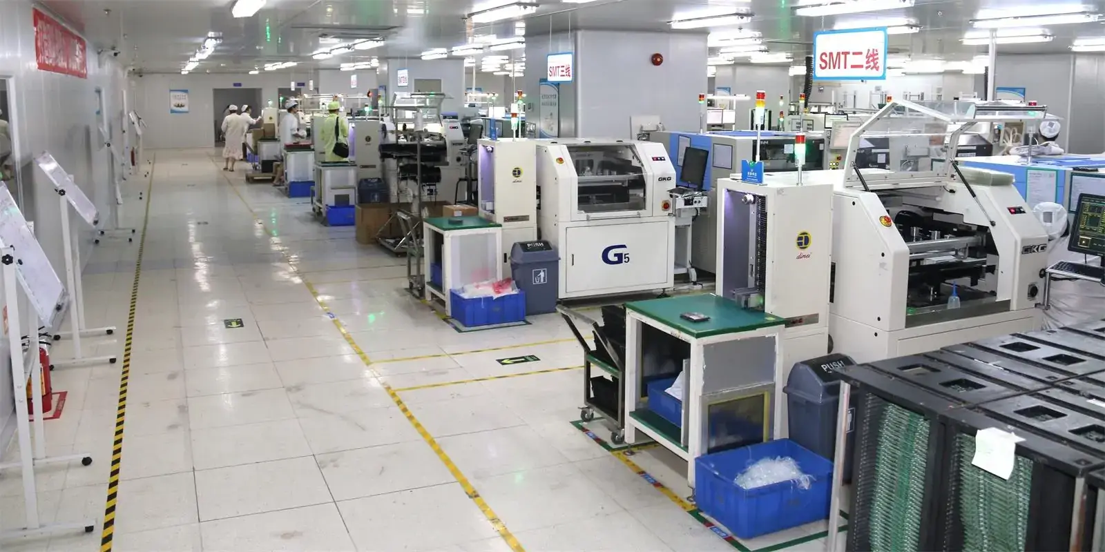
Can the Process Stay Stable at Volume?
Feeder settings, programs, stencil settings, profiles, materials, and fixtures can drift during repeat production, even though the nameplate speed of the equipment remains the same. To evaluate whether a vendor’s production method truly sustains high volume, analyze first-pass yield across at least three previous repeat lots rather than just one batch. The evaluation should also include Cpk values for specific critical characteristics defined for the board rather than an ambiguous capability claim, as well as the corrective-action history for recurring defects. If a vendor can provide only the yield from one batch, this indicates success at the first-article stage but does not demonstrate consistent volume stability.
How Does SUGA Scale Production Capacity?
SUGA verifies that the current design, BOM, and test plan still apply to the increased output before allocating the associated capacity based on the board, package mix, technology, and required volume. If a design change, substitution, or test change occurs during production scale-up, SUGA pauses capacity allocation for the affected lot and reevaluates it against the verified baseline to determine whether the change can be incorporated into the existing capacity assignment. Capacity allocation for an affected lot does not automatically continue on the assumption that it was verified by a previous order.
Which Certifications Matter?
SUGA applies IPC-A-610J assembly rules and J-STD-001J soldering requirements during controlled manufacturing. ISO 9001 supports the general quality-management system, ISO 13485 supports medical-device programs, and IATF 16949 supports automotive production programs. The certification scope, order specifications, and production records should remain consistent with the order.
High-Volume PCB Assembly Applications
Application fit changes depending on thermal loading, connector type, traceability, FCT coverage, service life, and specific industry requirements. Thus, each type of board requires a different manufacturing and verification emphasis.

Automotive Electronics
Typical automotive applications include body control, lighting control, infotainment, and power distribution, which commonly combine densely populated SMT with mechanically loaded connectors or power components. Controlled component lots and substitutions protect long production runs. Wave or selective soldering completes the THT process. Connector inspection, polarity inspection, and product-defined I/O, communication, or power tests cover the defined functions.
Automotive programs use IPC-A-610J, J-STD-001J, and automotive-specific quality controls. A recurring failure mode to discuss with suppliers is solder fatigue at mechanically loaded connectors under vibration and thermal cycling. Although these joints may pass AOI and first-pass FCT, failures can appear months into field service. As such, the real evaluation question is what accelerated-stress data or retained-sample data are available beyond the initial FCT.
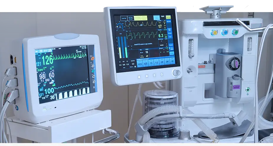
Medical Devices
Patient-monitoring, diagnostic-sensor, therapy-control, and medical-display boards can include fine-pitch packages with strict material and test traceability. The controlled BOM controls substitutions, while SPI and AOI monitor production; X-ray provides coverage for hidden solder joints beneath fine-pitch packages. Product-specific FCT verifies power-up, sensor inputs, interfaces, or communication with the receiving system.
ISO 13485 medical programs use quality controls for material and test traceability. A fine-pitch sensor-interface package can pass FCT during manufacture and still present reliability issues later because of hidden voids beneath the package. Thus, buyers should determine whether the package is subject to documented X-ray acceptance criteria and whether full-lot screening or random sampling is required.
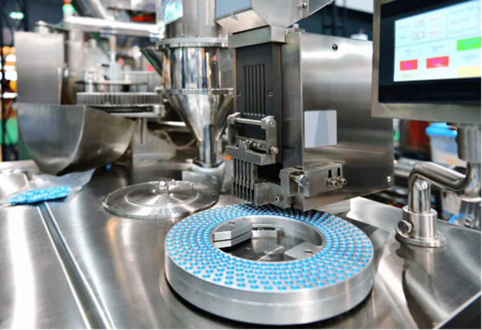
Industrial Automation
The types of assemblies used in industrial automation projects vary greatly, such as PLC I/O, robot motion control, motor drive, machine sensor, and HMI boards, because these assemblies often have very high-density logic next to THT field or power connectors. Industrial automation assemblies often require mixed-technology routing, selective soldering, connector support, and long-term control over components. The tests used to verify the performance of industrial automation products will typically be performed on I/O, motor-control, sensor, interface, or communication functions defined by the product. Because the dense control area and the mechanically loaded connector area are different, there may be different soldering-control requirements in the two areas.
One practical risk associated with industrial automation products is cumulative thermal exposure during manufacturing. As an example, heavy THT connectors may require longer selective-soldering contact times or higher localized heat, while adjacent dense SMT logic must remain within its approved thermal limits during the earlier reflow stage. Using separate thermal-profile controls and fixture designs for the connector and dense SMT areas will produce more reliable soldered connections than relying on a single soldering condition for the entire board.

Consumer Electronics
The types of components used to manufacture consumer electronic devices such as smart-home controllers, wearable charging devices, personal-device mainboards, and connected appliances can include very small 0201 components and fine-pitch packages, as well as multiple versions of the consumer electronic device. In manufacturing consumer electronics, small positioning errors that occur when printing or placing components on the PCB will scale very quickly over a long run. Stable stencil control, SPI, AOI, and risk-based X-ray will help reduce the risk of these types of errors.
Because the manufacturing process involves many different components and many different models of the same type of consumer electronic device, it is crucial that the BOM and program accurately differentiate between model variants. The types of tests used to verify the performance of consumer electronic devices will typically include power-up, wireless, sensor, or user-interface functions.
In consumer electronics, a common failure mode is that the wrong model firmware or BOM variant is erroneously loaded onto a shared platform. While the incorrect firmware or BOM variant can still pass FCT, it will ultimately fail in the hands of the consumer. It is important that documented variant-to-serial mapping be maintained and verified during FCT to ensure that the wrong firmware or BOM is not loaded onto a device. Test coverage alone will not provide a sufficient level of risk mitigation for a consumer electronics manufacturer.

Telecommunications Infrastructure
Solutions for managing base stations, router or switch functions, optical interfaces, RF support, and timing boards utilize BGA/LGA and similar fine-pitch packages, high-pin-count connectors, and double-sided assembly. Paste, placement, and reflow-control procedures support the assembly process, while X-ray inspection covers hidden solder joints. ICT or product-defined FCT covers assembled electrical behavior. Ethernet, optical, communication, or clock testing takes place according to the product specification.
While stack-up and impedance are considered bare-PCB control parameters, they also serve as the basis for establishing the baseline for the assembled board. On RF-adjacent or high-speed assembled boards, variations in solder volume, connector misalignment, or incorrect package placement can alter the electrical behavior of the assembled interface even when the bare-PCB impedance is correct. In instances where the assembled interface is electrically critical, product-specific signal-integrity or RF testing may be used rather than relying only on bare-board impedance verification to demonstrate final system performance.

Energy Systems
Solutions for battery management, energy-storage communication, power-conversion control, and charging control employ a combination of dense control circuitry, heavier copper, higher thermal mass, and THT power connectors. The solder profile must match the copper weight, PCB thickness, and mass of the components mounted on the board. The typical soldering technique for the power connections is wave or selective soldering, with inspection focused primarily on polarity, connectors, and heat-sensitive locations. Product-defined power-up, sensor, communication, protection, or load tests verify the performance of the assembled PCB.
Due to the relatively large copper mass and thermal mass at the power-connector locations on the PCBs, marginal solder joints on power connections are a recurring hidden risk. A marginal solder joint may be capable of carrying the full rated current during a brief FCT but may fail once placed under a sustained load. Thus, an extended load or burn-in step beyond the standard FCT cycle is a better indication than simply verifying that all protection tests were completed successfully.

IoT Devices
Wireless sensor nodes, smart-meter communication modules, trackers, and small gateways have many tiny components, including fine-pitch ICs, installed in limited inspection spaces. DFM and DFT define pad locations, stencil design, programming methods, and test-point access for production setup. SPI and AOI are used to monitor visible component assembly, while X-ray imaging provides a means of assessing hidden solder connections associated with fine-pitch IC packages. Updated hardware revisions and accompanying firmware versions must remain aligned. Testing of power, wireless communication, interfaces, or sensors occurs at the completed-assembly level.
The tight spacing of components creates a recurring risk of concealed solder bridges or inadequate paste transfer beneath fine-pitch IC packages that cannot be detected by AOI from the top of the assembly. Therefore, documented X-ray sampling coverage for each applicable package type provides a practical safeguard rather than relying on a general statement of inspection capability.
Data-Center Hardware
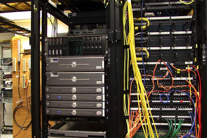
PCBA assembly and manufacturing require panel integrity throughout the production cycle. As PCB assemblies increase in density and complexity, assembly- and manufacturing-related stress on panels also increases. This increase in stress can lead to more failures. As the industry moves toward a larger share of PCBA volume being produced using mixed technologies, such as THT and SMT components, panels may flex more during PCB assembly. As such, a failure mode common to large, complex panels is BGA joint cracking due to panel warpage during reflow. If FCT does not detect this defect, it may be detected only when the product is subjected to sustained thermal loads during service. The evaluation question is not whether X-ray was performed, but whether the supplier tracks warpage data for each panel lot produced.
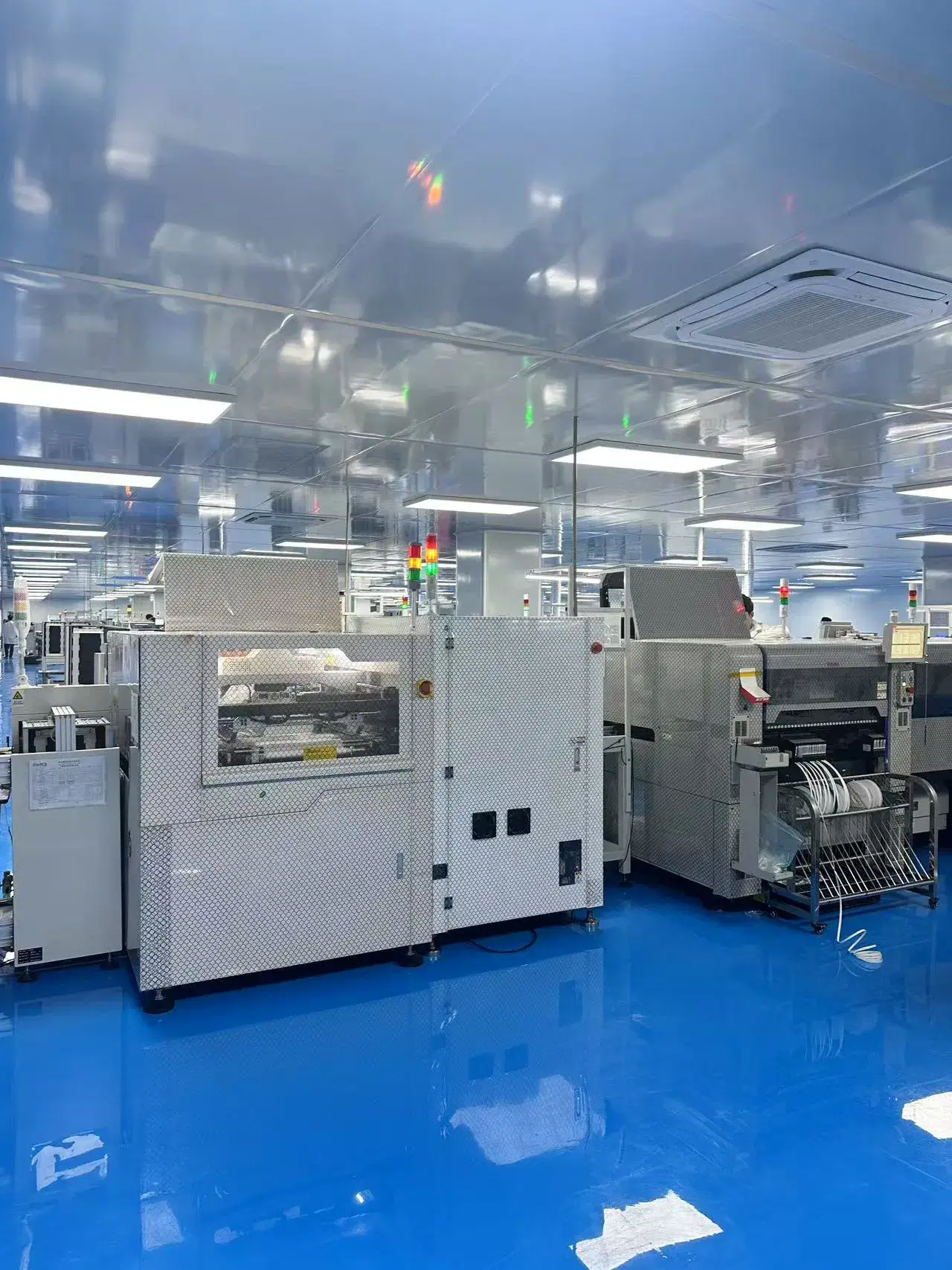
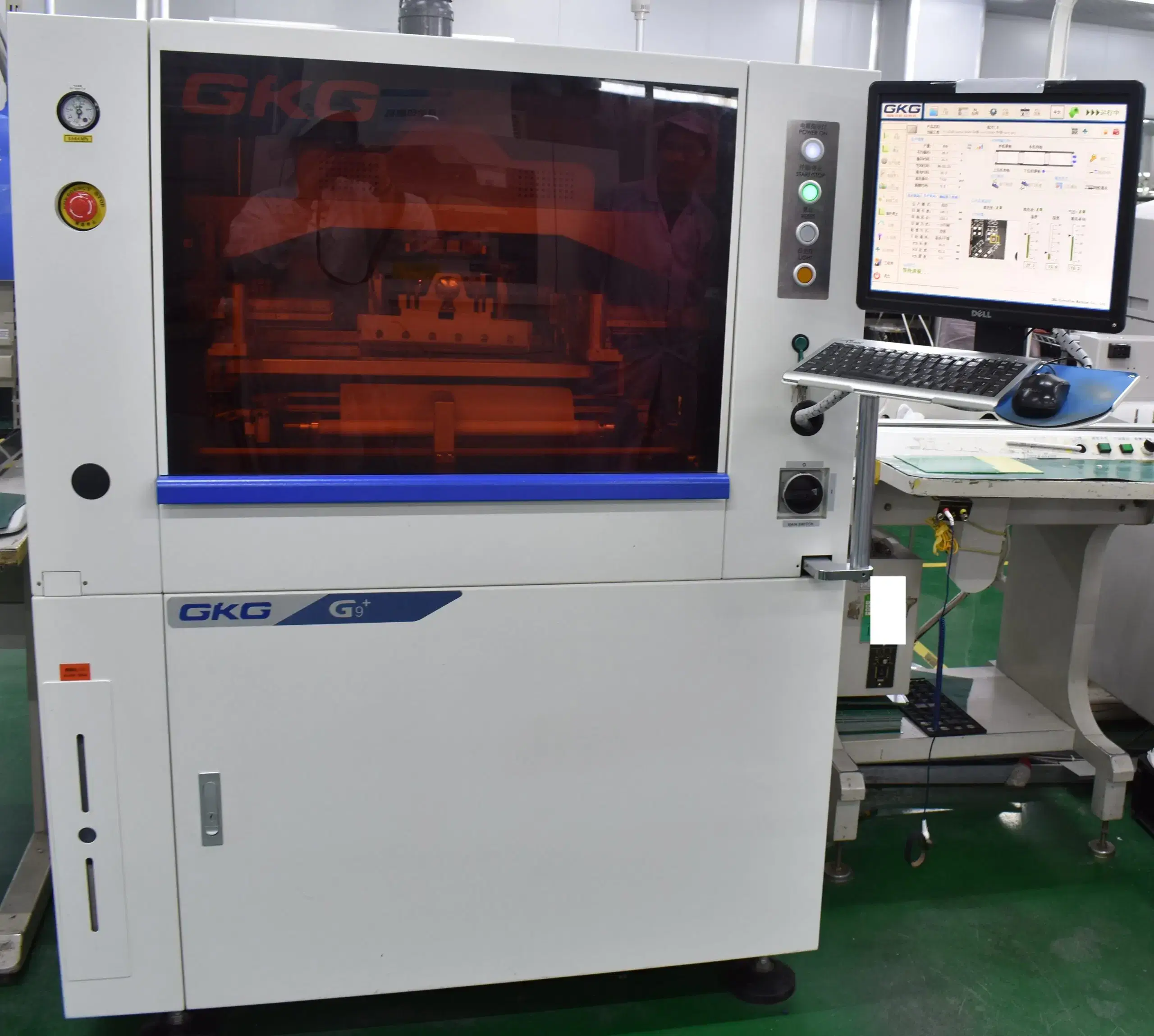
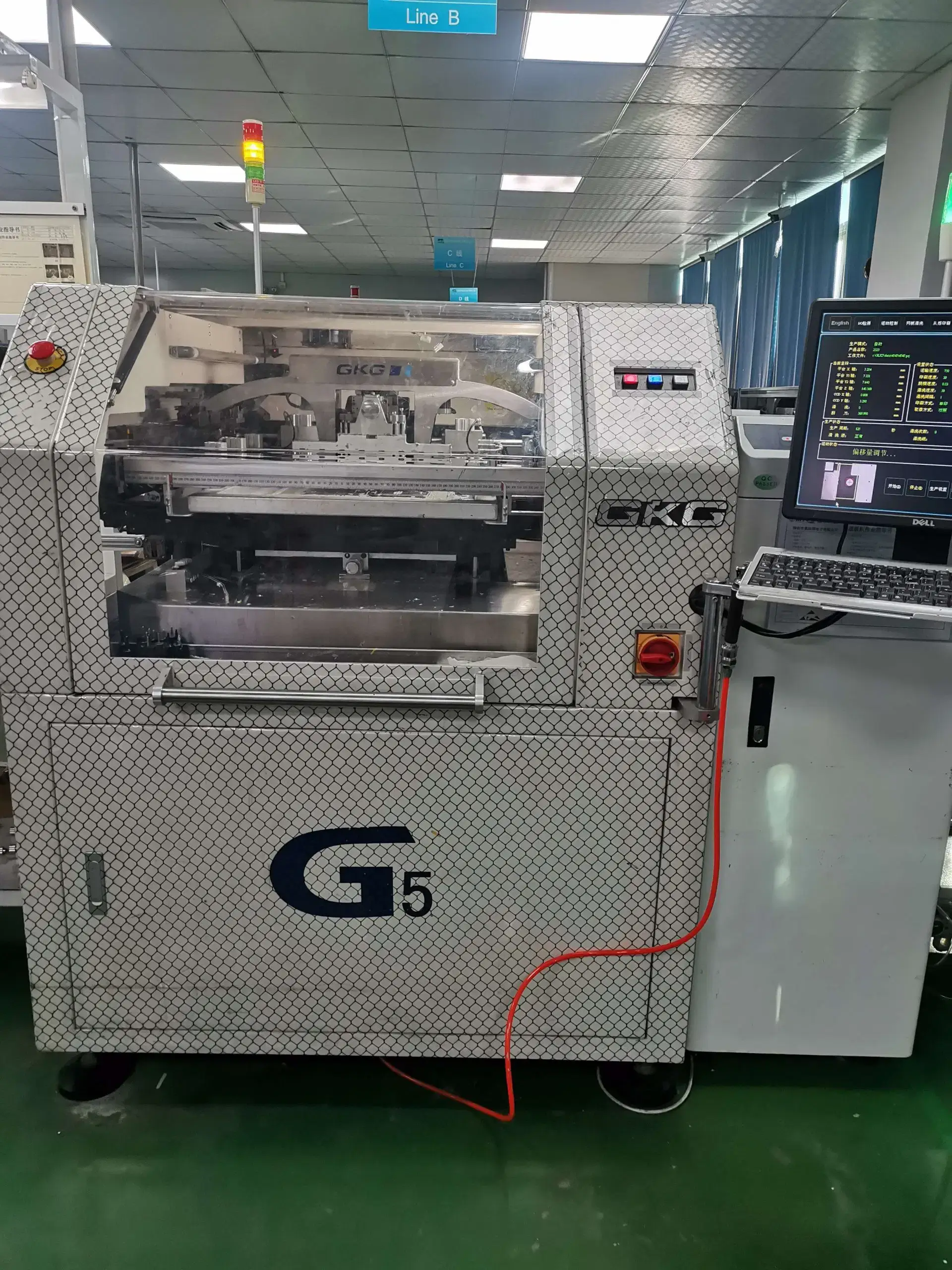
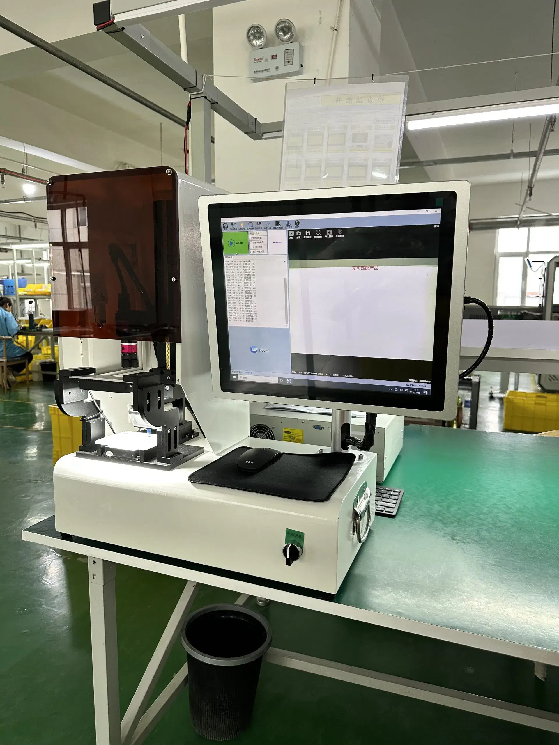
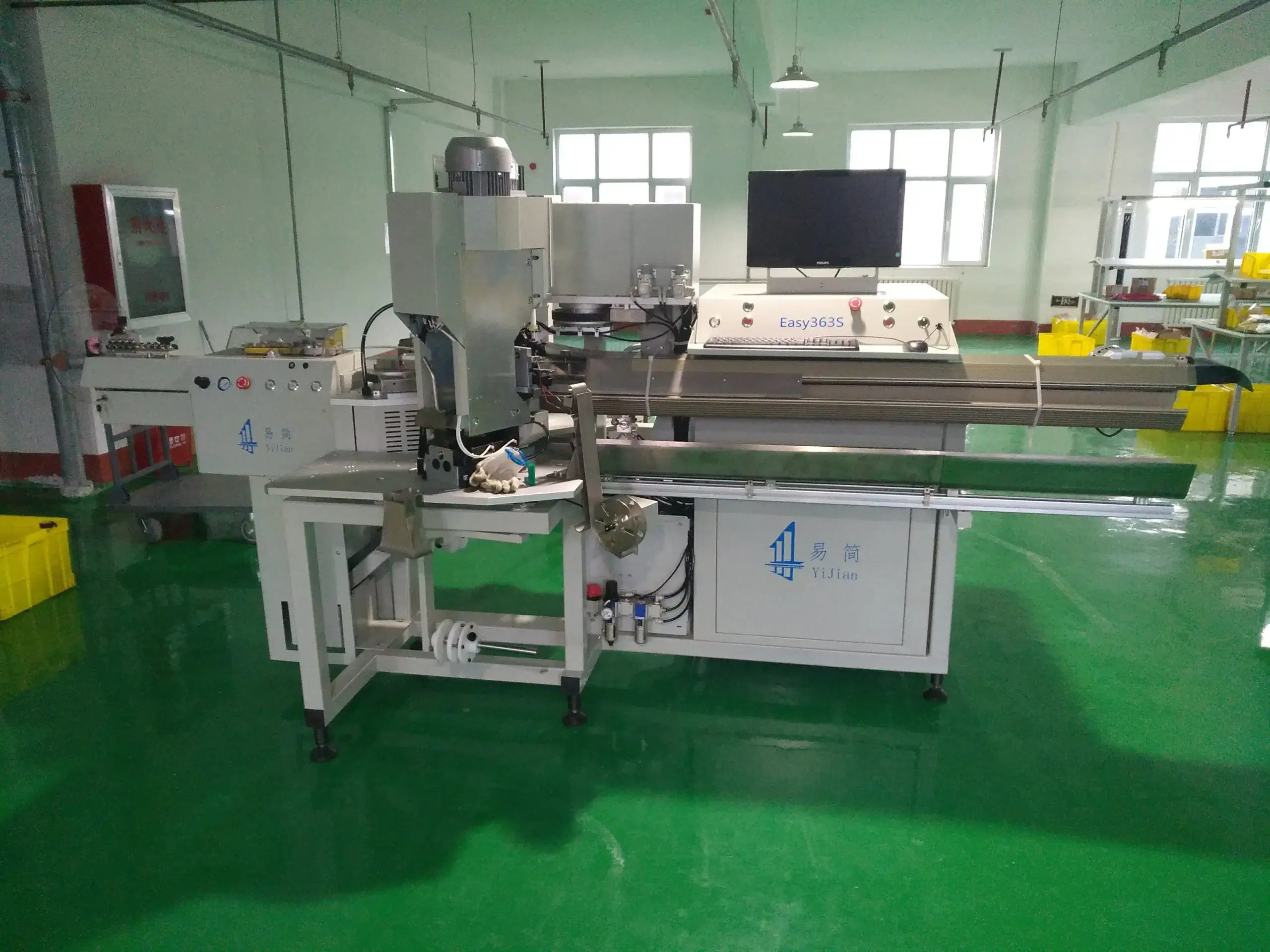
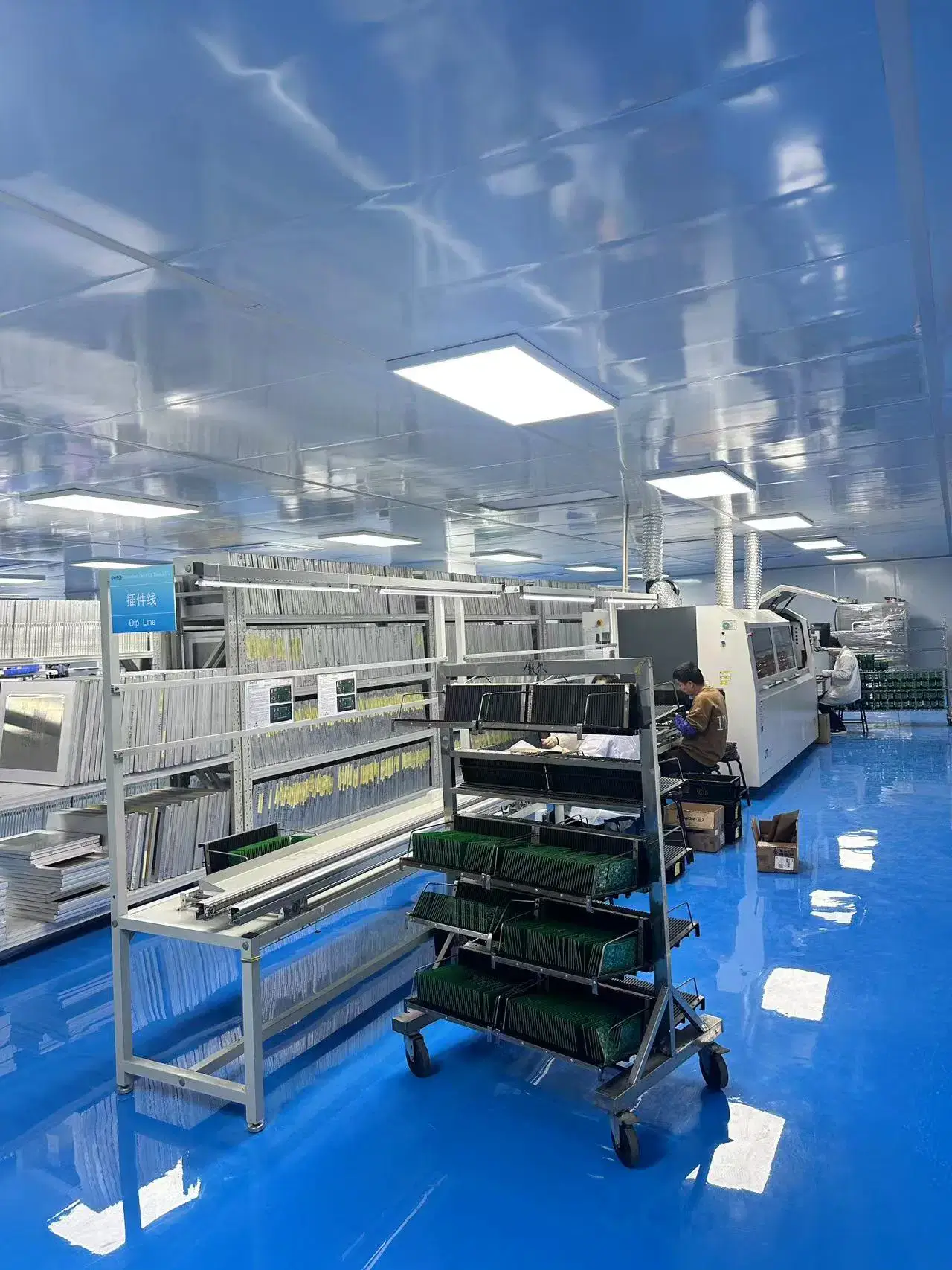
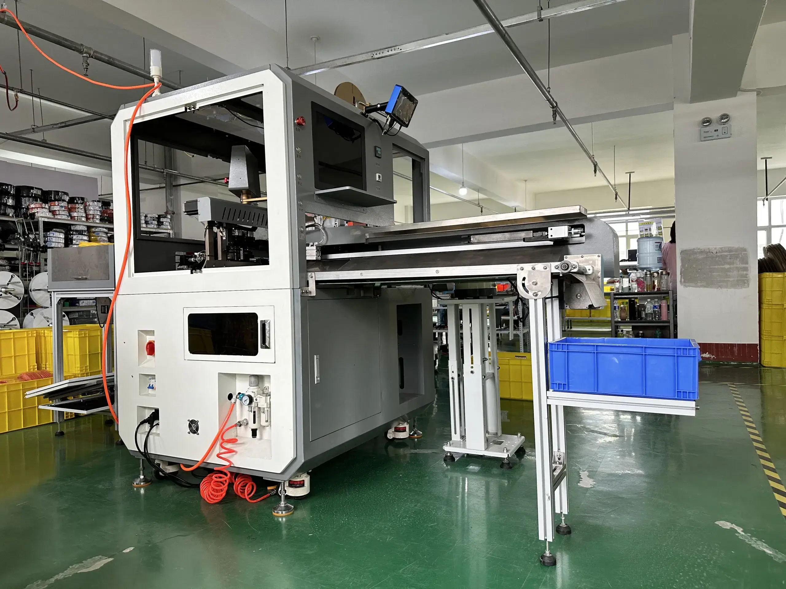
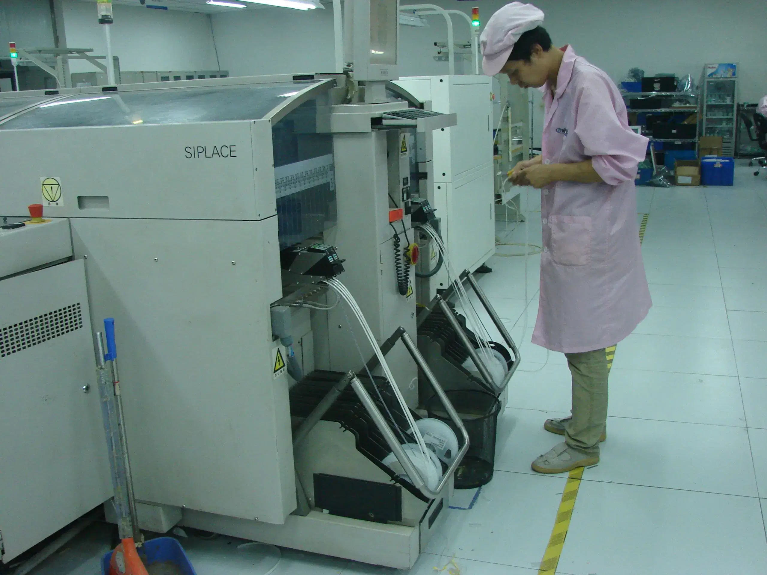
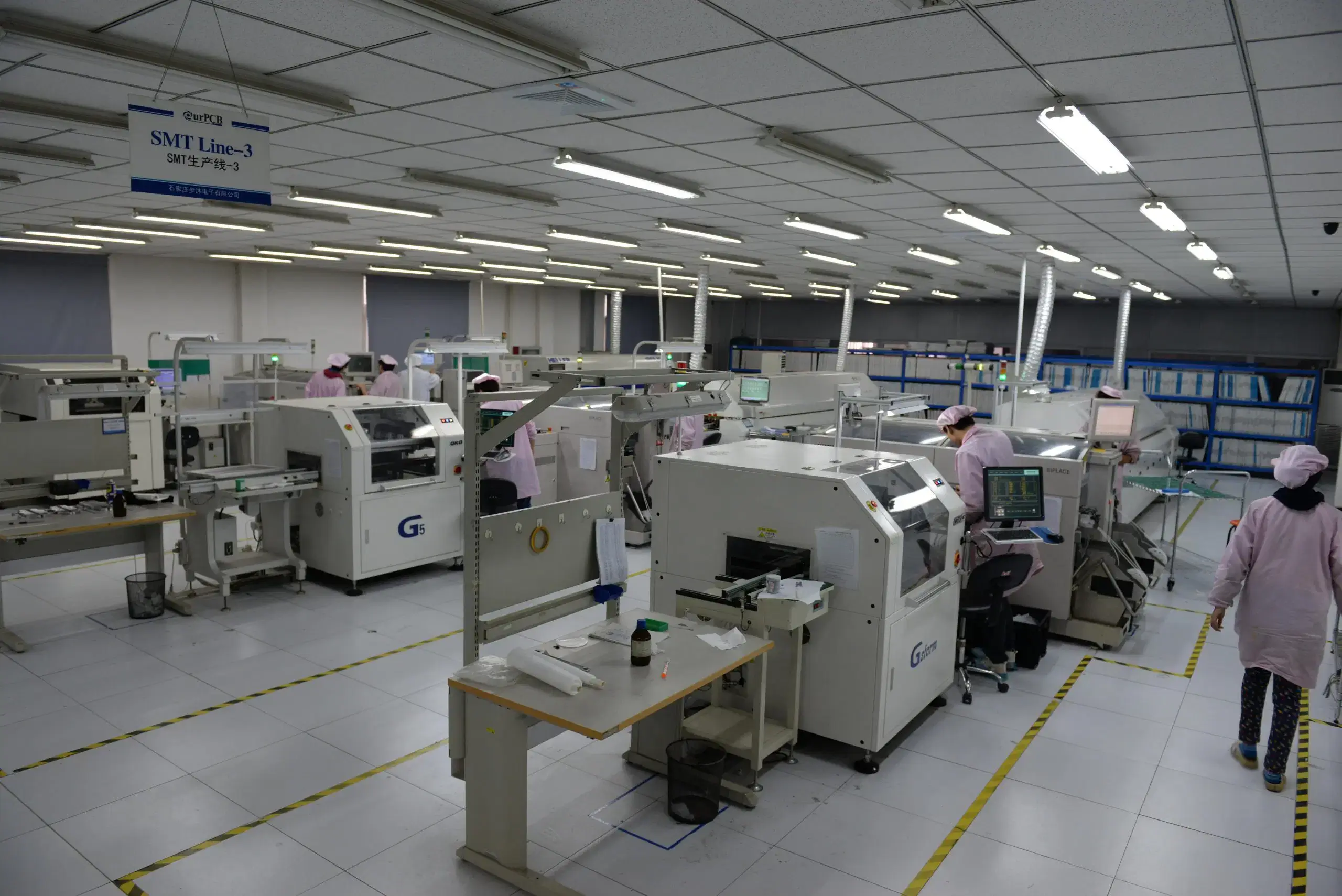
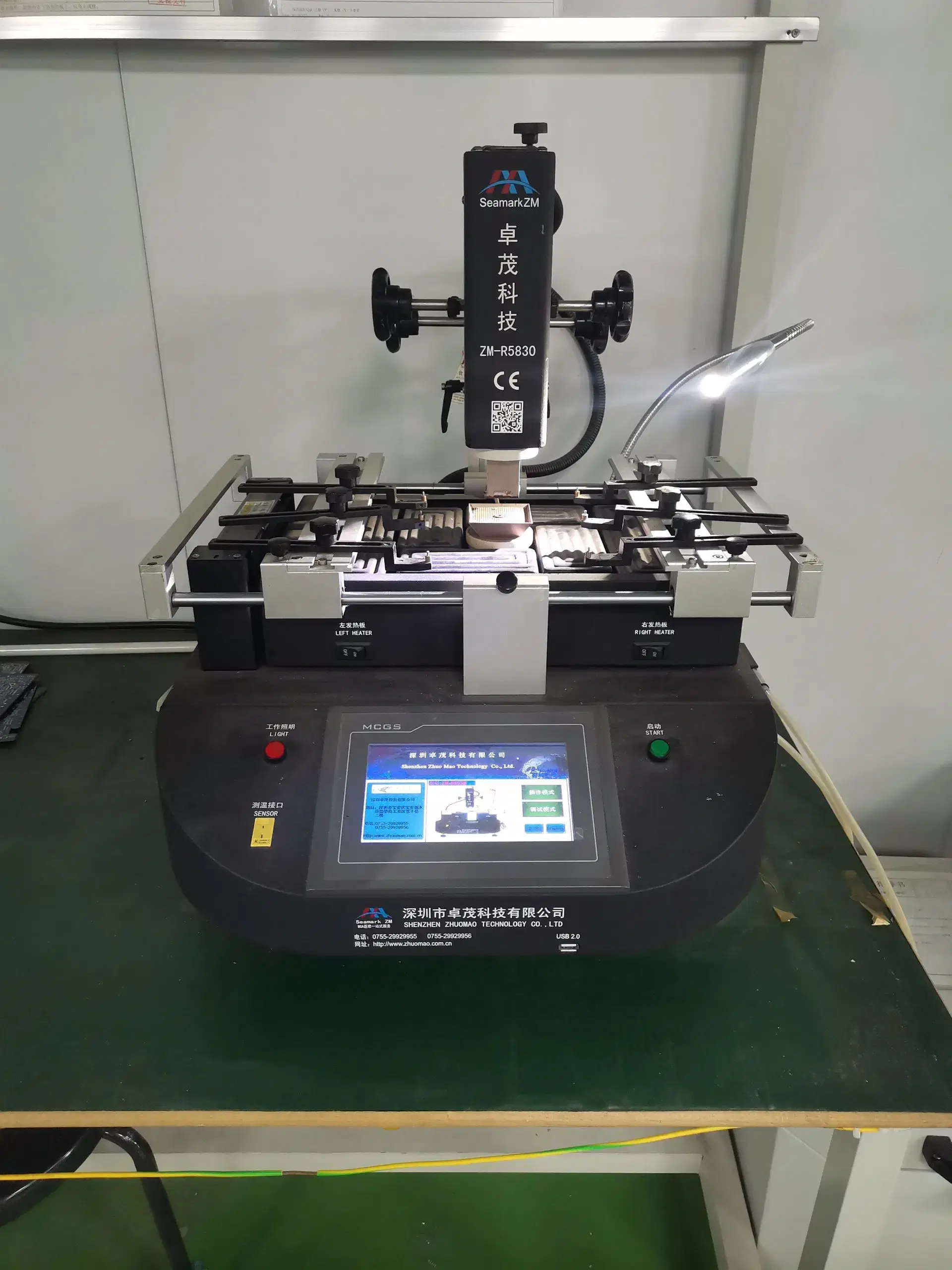
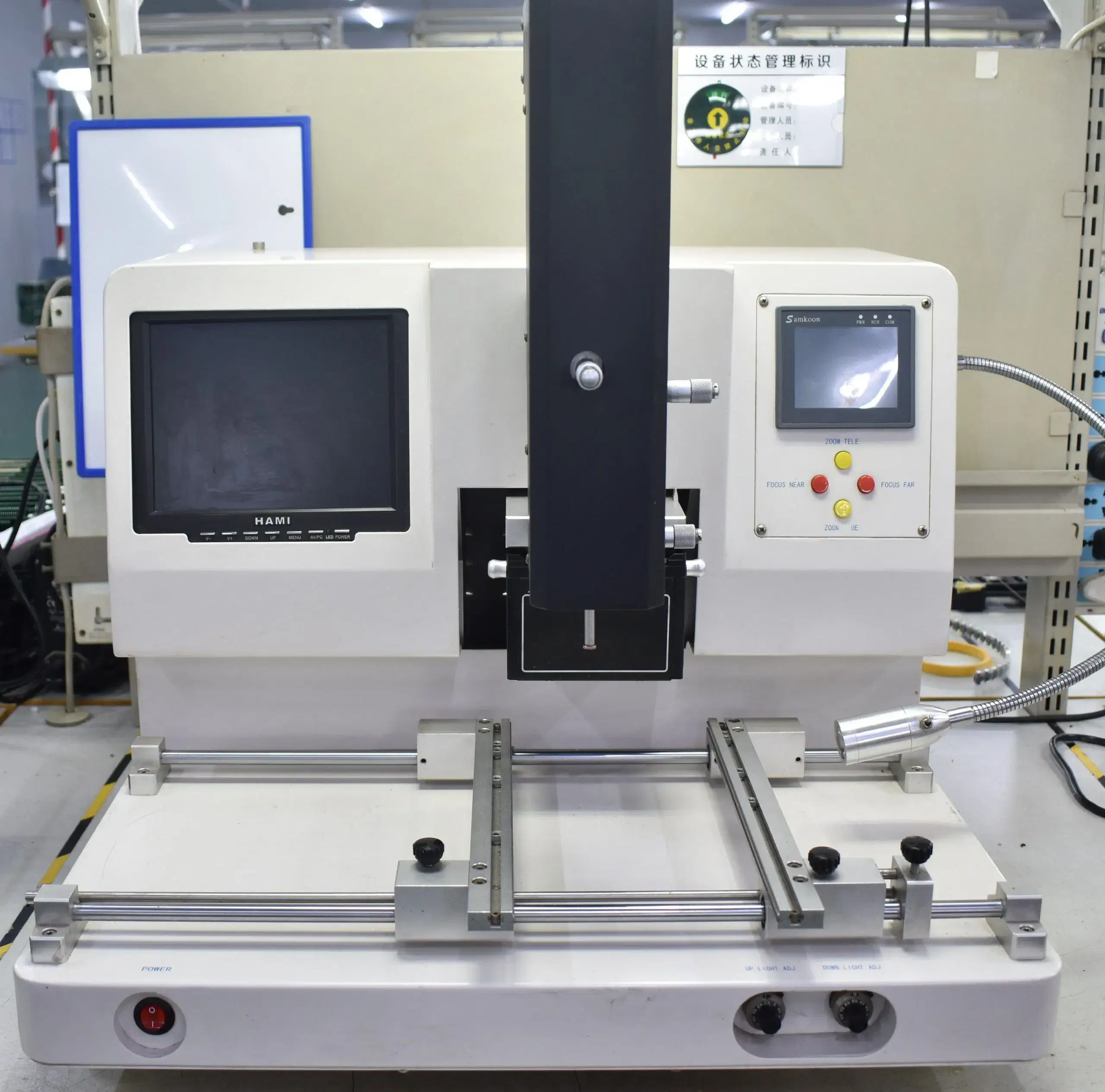
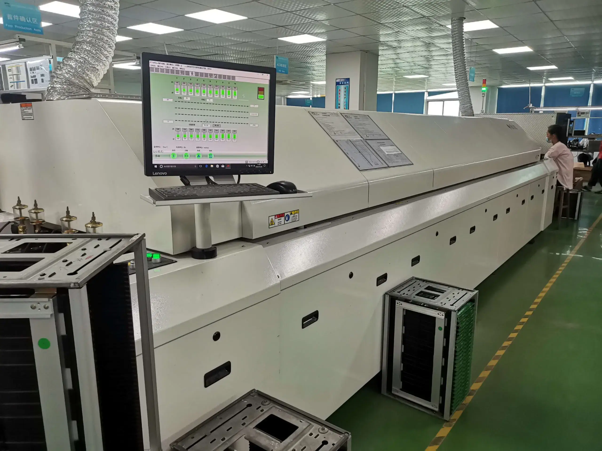
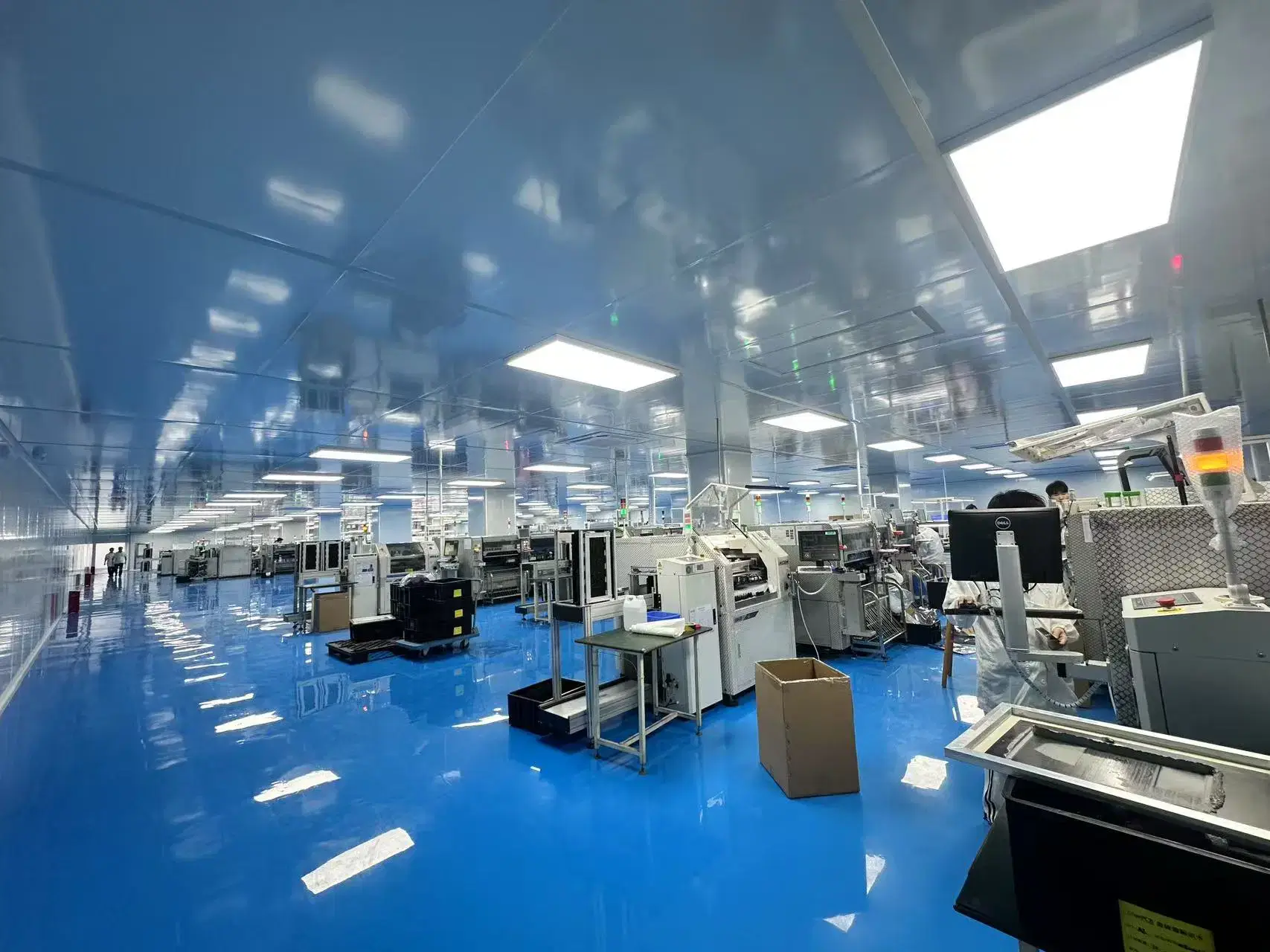
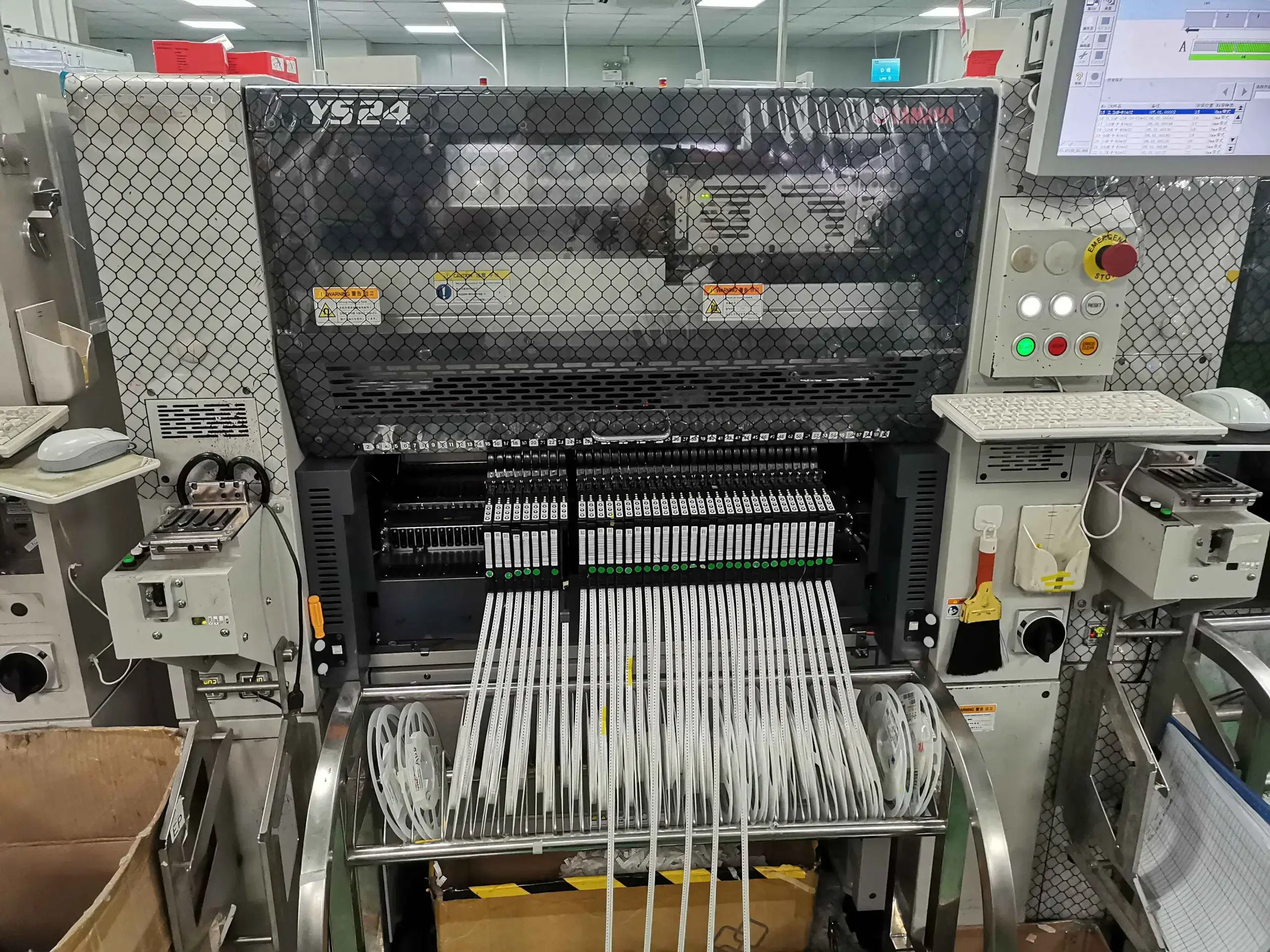
Our PCB Factory Gallery
Frequently Asked Questions
High-volume production can support custom boards, including those designed with custom components, assembly methods, and FCT, when the custom design, BOM, tooling, and manufacturing-process data are sufficiently stable to allow repeat production. Customization and large-scale production are compatible within the same production system. Specifically, custom boards produced through high-volume production should have a placement program, fixture, and test files unique to the custom board design. However, the manufacturing data must be frozen and repeatable; the design itself does not need to be standardized.
Yes. Both models can scale, provided that responsibility for sourcing, approved manufacturers, alternative parts, lot control, and shortage decisions is clear. For SUGA-sourced models, SUGA coordinates the supply of materials used in the PCBA production process. For consigned models, customer-supplied materials are verified for identity, condition, quantity, and traceability before being placed on the production line. Authorized substitutions must follow the material-control process outlined in the product specifications. For consigned materials, if a shortage is discovered during kitting, production of the affected lot stops instead of triggering an unauthorized substitution. Any substitute must be approved by the customer before production restarts.
Yes. SUGA supports lead-free mass production using the specified lead-free alloy, solder paste, component finishes, solder profiles, and other soldering-process requirements. RoHS-related material and soldering requirements are considered across the entire assembled PCB. Therefore, a lead-free claim must cover all relevant materials used in PCBA production rather than only the solder paste.
Yes. High-volume PCBAs can be reworked when defects are recoverable and the repair methods are approved for the specific defect class. During rework, proper controls are used to remove defective assemblies from production, identify the defect, determine its root cause, and apply the prescribed controlled rework instructions and testing. The rework result remains associated with the lot or serial-number record. When high-volume PCBAs are reworked, there is typically a limit on the number of times each board position may be repaired before the board is scrapped rather than repeatedly repaired, because multiple heat cycles at the same solder joint can degrade its structure.