Upload BOM & Gerber


There is no single specification for an agriculture PCB assembly; rather, agriculture PCB assembly requirements define how an assembly must perform based on how the product will be installed, what equipment it will be connected to, and the environmental conditions it will encounter. Terms such as “rugged,” “weatherproof,” “protected,” or “tested” do not define what the assembly must withstand or how acceptance will be measured.
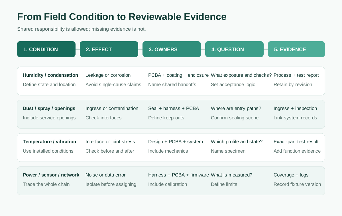
An irrigation controller, tractor display, pump controller, and battery-powered soil sensor impose different electrical, mechanical, coating, connector, and functional-test requirements on an agriculture PCB assembly. The requirement specification for each agriculture PCB assembly needs to describe the actual product being manufactured and convert field conditions into measurable acceptance criteria that can be used to manufacture or validate the PCB assembly.
- Define how the product will be installed and operated, its interfaces, and the potential consequences of failure before selecting environmental or electrical tests.
- Separate PCB protection from enclosure ingress protection, connector sealing, cable entry points, vents, and final product assembly.
- Ensure that functional tests use representative sensor configurations, cable lengths, valve coils, relays, pumps, motors, power interruptions, and communication links rather than unloaded power-on checks.
- Ensure that inspection, firmware, calibration, coating, and functional-test results can be linked to an individual product revision, lot, or serial number.
Contents
show
What Makes Agriculture PCB Assembly Requirements Different?
Agricultural electronics operate in considerably different environments from those of many other electronics. A tractor display located inside a cab may be subject mainly to operating vibration, vehicle power fluctuations, and connector movement. A greenhouse node must address persistent humidity and condensation risk. An irrigation controller may control inductive loads through long outdoor cables, while a soil sensor can combine exposed sensor surfaces, high-impedance analog signals, low sleep current, and wireless transmission inside one small enclosure.
The first question is which part of the product is being evaluated. IEC 60529 applies to enclosure protection against access, solids, and water. Conformal coating reduces the risk of surface leakage and contamination on the circuit board, but it does not provide an IP rating for a completed product. The final enclosure, connectors, cable glands, vents, sensor openings, service covers, and final assembly determine the product-level result. The description of an agriculture PCBA must include the information required to provide a quotation or perform testing.
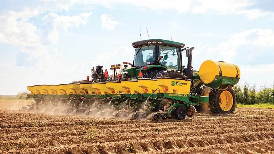
Step 1: Define the Use Profile and Failure Consequences
The use profile defines how the equipment will be used and its expected behavior in the field. Engineering, procurement, quality control, and the PCBA supplier should all have the same understanding of how the equipment will be used and the potential consequences of failure.
- Locate the electronics. Identify whether the assembly is located within a tractor cab, an engine or hydraulic compartment, a mounted implement, an outdoor enclosure, a greenhouse controller, an irrigation node, a pump panel, a telematics unit, or an exposed sensor housing.
- Describe the actual exposure. Identify temperature changes, condensation, sustained humidity, dust, mud, fertilizer or pesticide residue, wash spray, vibration, shock, long cable runs, inductive loads, wireless links, grounding paths, and power interruptions.
- State the operating and service conditions. Define whether the product is electrically powered during exposure, how it is cleaned, stored, transported, calibrated, and replaced, and whether field servicing is expected during planting or harvest.
- Define the failure consequences. Describe how a delayed soil reading differs from an energized valve, an uncontrolled pump, a lost implement command, or a safety-related function. This includes the required safe state, diagnostics, restart behavior, and recovery time.
Humidity testing methods should match the moisture mechanism. IEC 60068-2-78:2025 describes sustained high humidity without condensation. This is valid when the risk is prolonged exposure to non-condensing damp heat. Equipment subjected to day-and-night temperature changes or installed in enclosures that “breathe” and may develop visible surface moisture needs a cyclic damp-heat method such as IEC 60068-2-30:2025. Condensation can affect leakage, corrosion, sensor drift, and connector behavior differently from sustained non-condensing humidity exposure.
The field designation “outdoor agricultural use” requires more detail. The specification needs to define how the enclosure will be exposed, how connectors will connect to field wiring, how wash exposure will be handled, the operating state during exposure, the power source and power disturbances, and how the equipment will recover after the event.
Step 2: Convert Field Conditions into Assembly and Test Requirements
A field symptom typically does not identify a specific failed component but may be related to other factors that contributed to the failure. For example, moisture, intermittent data, unexpected resets, or loose connections can result from board-design issues, cleaning or manufacturing residue, coating issues, a connector, harness, enclosure, firmware, calibration, power source, or connected loads. Test requirements should connect the field condition to the failure mechanism, a controlled assembly or interface feature, and a result that can be retained.
Irrigation Controllers
Hazards stem from long valve cable lengths that create more resistance, ground offsets, noise pickup, and larger loop areas. Solenoid coils also generate inductive energy when de-energized. Although a controller may pass a bench test using short leads and resistive loads, an installed controller may reset, keep a valve energized, or misread a shared sensor when multiple channels operate together. To test all these conditions, functional-test fixtures should use the same cable lengths as the installed controller and include representative valve coils, repetitive switching, and simultaneous outputs. Testing should include supply interruption and open- or short-load conditions. Functional testing should verify that the system returns to a safe state following recovery from failure.

Pump Controllers
The pump controller must combine high-current pump switching with inputs for pump-performance parameters such as pressure, flow, level, and dry-run conditions. High starting current or contactor operation can cause the control power supply to drop, thereby injecting noise into the sensor and communication circuits. Therefore, the pump controller must provide acceptable performance under the following conditions: startup current spikes, repeated relay or contactor operation, overcurrent or dry-run conditions, sensor disconnection, thermal operation, restart permission, and the output condition following a brownout. Mechanical retention and post-vibration inspection must be performed for relays, transformers, inductors, terminal blocks, and other current-carrying connectors.
Soil, Nutrient and Environmental Sensor Nodes
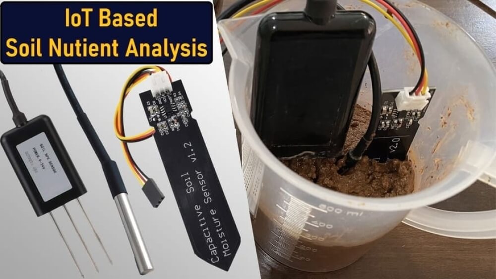
Because of the high-impedance nature of analog inputs to a sensor node, sensor readings can drift because of flux residue, cleaning agents, moisture, or coating applied too close to exposed sensor surfaces. A soil, nutrient, or environmental sensor node may meet an average-current target while failing during radio bursts because of inadequate battery voltage or during the warm-up period of the node and its sensors. Therefore, the validation process must differentiate sleep current from wake-up current. It must also evaluate sensor excitation, radio-transmit peaks, battery-voltage range, raw ADC stability, calibration, and post-coating behavior. All humidity, gas, pressure, and soil probes require an explicit coating keep-out area. Any cleaning or coating operation that changes the sensor response requires a calibration check.
Tractor Displays and Telematics Units
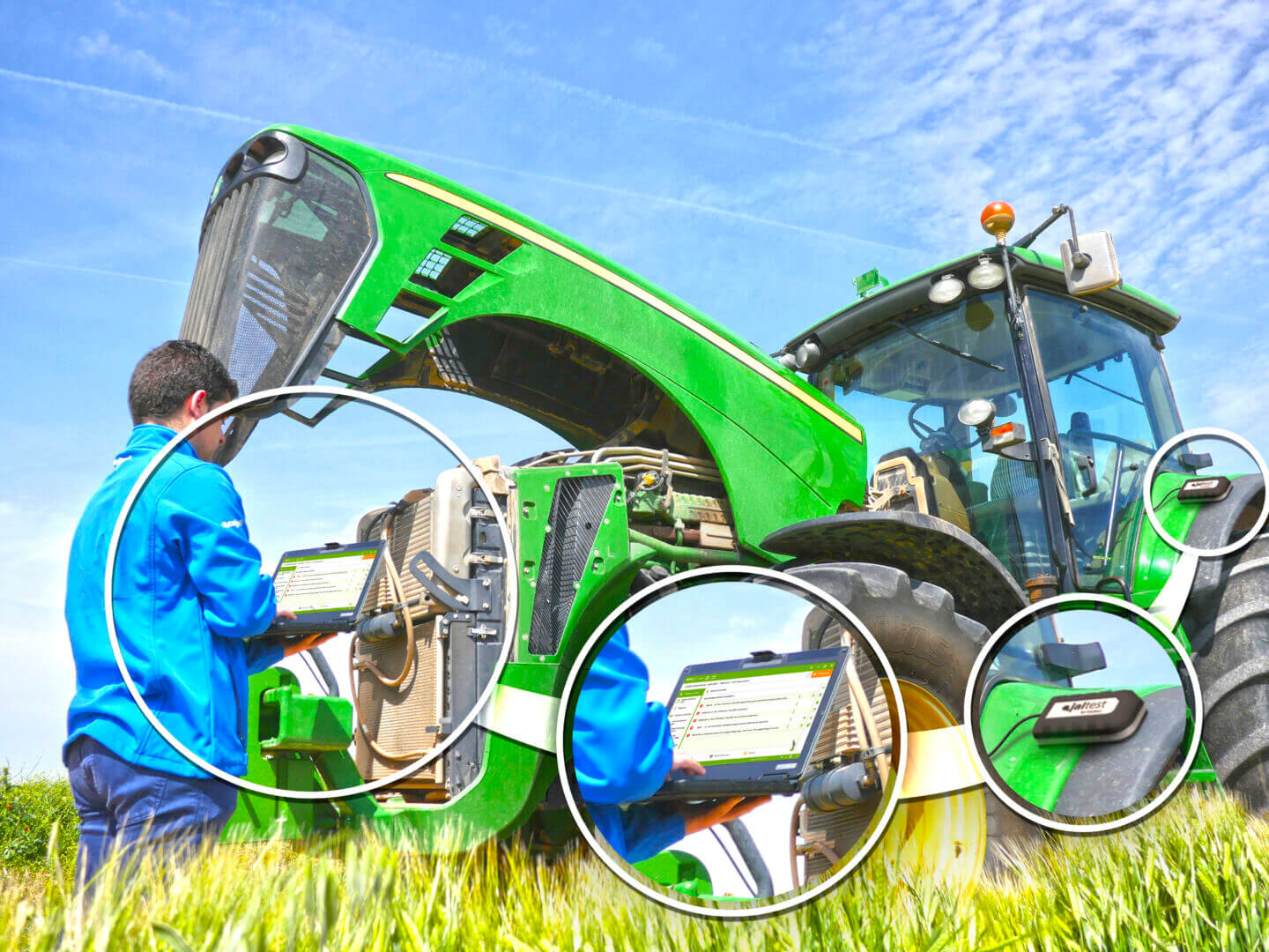
Tractor displays and telematics units have many characteristics in common with other vehicle-powered products. They experience vehicle power disturbances, vibration, harness movement, GNSS or wireless antenna conditions, and repeated communication loss. Testing also needs to include the installed connector and harness configuration, supply interruptions and restart cycles, reconnection time, retained product settings, data recovery, and antenna or RF integrity after coating and assembly. The vibration experienced by an unhoused PCBA during dynamic testing cannot be considered equivalent to the vibration transferred after the board has been integrated into the final enclosure with the display, connectors, brackets, and cable mass.
Step 3: Separate Board Protection from Product Ingress Protection
Conformal coating and potting are board-level controls and therefore do not validate connector mating surfaces, cable entries, enclosure joints, vents, pressure equalization, service covers, or the function of the completed product after assembly. Product ingress protection is established through the final enclosure configuration, including all installed connectors, glands, seals, vents, fasteners, and service features.
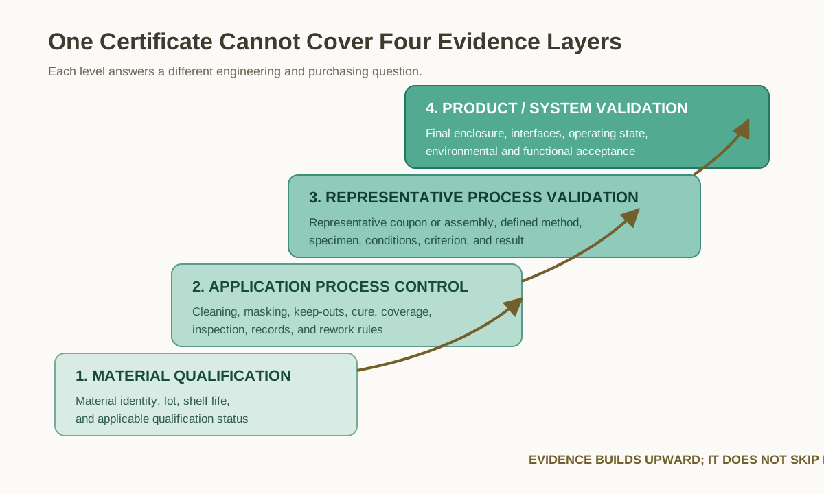
The requirements for a coating include the material, board cleanliness, masking map, coating keep-out areas, cure, thickness or coverage criteria, inspection method, repair rule, and electrical-test sequence. Soil, humidity, gas, and pressure sensors may have exposed areas that cannot be coated. GPS, LoRa, cellular, Bluetooth, and Wi-Fi antennas require material and clearance decisions that maintain RF performance. Masking is necessary for removable connectors, terminal blocks, calibration points, test pads, and serviceable fuses. Power resistors, switching devices, relays, and other heat-producing components require thermal review before coating or potting.
Conformal coating is suited to repairable electronics that require surface protection and controlled access to components. Potting provides additional mechanical support and a barrier against contamination, but it also adds weight, restricts heat flow, complicates inspection, and limits repairability. A gasketed enclosure can control product-level ingress, but it still relies on correct seal compression, connector installation, cable glands, vents, fasteners, and final workmanship. Outdoor agricultural products often combine these methods.
Step 4: Select Standards by Failure Mode
The standard selected depends on the product condition, intended market, applicable interface, and safety role. A family number alone does not define a test. Each project specification must identify the applicable part, contract-selected edition, severity, specimen, mounting arrangement, operating state, measurements, acceptance criteria, and retained report.
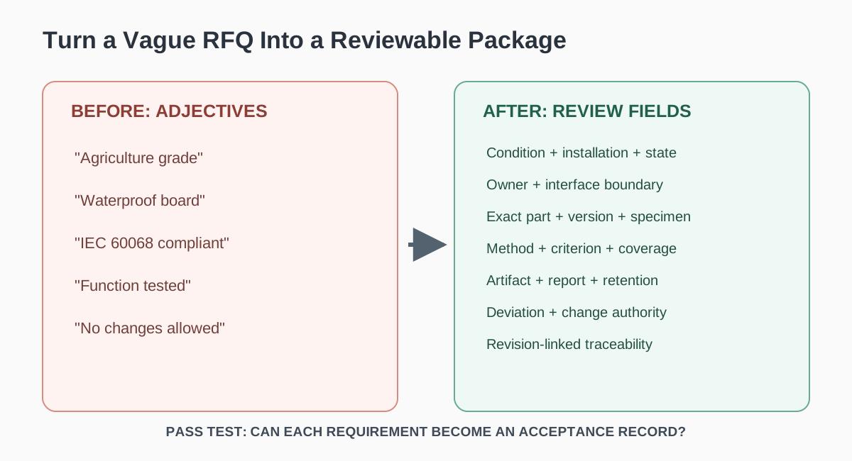
Workmanship standards answer questions about how to manufacture, inspect, and trace claims that a product meets the assembly requirements, but they do not prove that a valve controller will still function after inductive switching, a soil sensor will remain calibrated after condensation occurs on its surface, or a telematics unit will re-establish communication after a power interruption. To validate these types of performance, representative loads, interfaces, operating states, and acceptance limits are required.
Step 5: Evaluate Manufacturing, Inspection and Traceability
Supplier evaluation connects the product’s manufacturing claims to the applicable product revision and associated defect risk. A full list of inspection techniques, including AOI, X-Ray, ICT, FPT, coating inspection, or functional testing, is not enough; each method must be linked to the faults it can detect on the specific assembly and to the defects or structures that remain outside its coverage.
The BOM or AVL, approved substitutions, PCB and assembly data, connector orientation, firmware, calibration files, coating drawing, masking map, mechanical retention, and revision status are all controlled by the released package. Products that contain sensitive analog-input circuits, relays, high-current devices, wireless modules, and heavy connectors require controls for electrical accuracy and mechanical strength at the same time.
Process records include material lot numbers, soldering and rework, cleaning, coating or potting, masking, curing, coverage inspection, repair, and retention of heavy parts. Cleanliness is especially important around soil, humidity, nutrient, conductivity, and pH inputs. Residue or moisture can change readings without producing an apparent physical defect. Representative SIR evaluations support process control, while actual sensor-input and calibration tests confirm the operating characteristics of the product.
Inspection is based on the type of defect being detected. AOI checks component presence, polarity, orientation, visible solder conditions, and the pre-coating condition. X-Ray adds value for devices such as BGA, QFN, and other bottom-terminated components; however, not all boards require X-Ray. Accessible opens, shorts, component values, and power networks can be assessed through ICT or FPT. Firmware, communication, sensor inputs, loaded outputs, fault response, and recovery can be confirmed through functional testing.
Traceability follows the failure modes and service model. Lot and serial numbers provide a reference for the PCB revision, critical-component lots, firmware, calibration, coating batch, fixture revision, functional-test results, nonconformance disposition, and approved deviations. These records are critical for distributed fleets of equipment or equipment used only during limited planting or harvesting windows.
Step 6: What Information Is Required Before Quotation?
To prepare a quotation for a new product, the manufacturer needs much more than Gerber files and a BOM. The quotation package includes the product function, installation location, target markets, critical outputs, consequences of failure, operating and storage conditions, cleaning method, maintenance model, enclosure status, and whether the product operates during humidity, vibration, temperature changes, load switching, or power interruptions.
The released assembly data includes PCB files, BOM or AVL, placement and assembly information, approved substitutions, mechanical drawings, connector definitions, harness drawings, representative cable lengths, sensor types and ranges, solenoid or relay loads, pump or motor interfaces, communication methods, power and grounding behavior, diagnostics, firmware, calibration files, coating or potting instructions, and revision status. This information directly influences fixture design, programming, load simulation, inspection coverage, and acceptance limits.
The acceptance package defines electrical checks, functional stimuli and loads, cable configuration, fixture and firmware revisions, calibration method, limits, fault conditions, recovery behavior, unit or sample coverage, report format, traceability level, nonconformance handling, deviation approval, record retention, and change authority. Providing these inputs during the board review allows the PCBA manufacturer to focus on manufacturability and test coverage rather than attempting to reconstruct how the board will ultimately be used during quotation.
Frequently Asked Questions
Q1. Does conformal coating make an agricultural PCBA waterproof?
No. Conformal coating is applied to selected surfaces of an agricultural PCBA for protection. Product ingress protection depends on the enclosure design, installed connectors, cable glands, vents, seals, joints, sensor openings, service covers, and final assembly. While conformal coating reduces the risk of surface leakage or contamination, the finished product still requires enclosure-level validation.
Q2. How should intermittent agricultural sensor readings be investigated?
Replace the field sensor with a known input and take measurements at the controller connector before relying on processed software or cloud data. Compare a short cable with the installed cable length, check for variations in sensor supply and ground voltage, and record the raw data. Repeat the test during valve switching, radio transmission, humidity exposure, or power interruptions. A fault that appears after cleaning or coating may indicate residue, leakage, masking, or calibration issues. A fault that follows cable movement indicates a possible connector or harness problem.
Q3. What functional test is required for an irrigation or pump controller?
The two controllers use similar testing principles, but their failure modes differ, so a generic checklist will not account for each controller’s specific failures. The irrigation controller requires the installed valve cable length and a real coil load to determine whether a reset occurs or a valve remains energized while multiple channels switch at the same time. The pump controller requires loaded startup current and contactor cycling to determine whether a brownout occurs on the control supply or whether sensor feedback becomes inaccurate when the motor starts. In both cases, the fixture, firmware, load configuration, limits, raw results, and controller serial number need to be documented; however, the load profiles for the irrigation controller and pump controller are not interchangeable.
Q4. Does an IP-rated enclosure remove the need for conformal coating?
No. An enclosure’s IP rating represents its ingress protection when tested in the specified closed configuration. Agricultural equipment may be opened for calibration, sensor replacement, or seasonal service. Each field-service opening changes gasket compression, connector seating, and cable-gland installation under field conditions. Conformal coating on the circuit board continues to protect the assembly through those service events, so enclosure sealing and board coating form a deliberate two-layer protection strategy rather than redundant controls.
Q5. Can one PCBA design be qualified once and reused across different agricultural equipment types?
Only if the PCBA application is defined as the combination of all equipment types in which it will be installed rather than the average application. For example, a single PCBA design used in both a tractor-cab display and a stationary irrigation panel needs to meet the tractor cab’s mounting and vibration profiles as well as the irrigation installation’s long-cable and inductive-load profiles. Qualification for only one application should not be assumed to cover the other.
Conclusion
Agriculture PCB assembly requirements must be developed by understanding the environmental conditions associated with use and the requirements of the specific equipment. A tractor-cab display, irrigation controller, pump controller, and soil sensor do not share one rugged specification because each is subjected to a different combination of moisture, electrical power, mechanical loading, sensing, wireless communication, service frequency, and failure consequences. Identifying these differences in advance allows the manufacturer to control the assembly process and gives the buyer clear acceptance criteria for the finished product.
References and Sources
- IEC 60529, Degrees of Protection Provided by Enclosures (IP Code).
- IEC 60068-2-78:2025, Environmental Testing – Damp Heat, Steady State.
- IEC 60068-2-14:2023, Environmental Testing – Change of Temperature.
- IEC 60068-2-27:2008, Environmental Testing – Shock.
- IEC 60068-2-6:2007, Environmental Testing – Sinusoidal Vibration.
- ISO 14982 series, Agricultural and Forestry Machinery – Electromagnetic Compatibility.
- ISO 11783 series, Tractors and Machinery for Agriculture and Forestry – Serial Control and Communications Data Network.
- ISO 25119 series, Tractors and Machinery for Agriculture and Forestry – Safety-Related Parts of Control Systems.
- IPC-A-610, Acceptability of Electronic Assemblies.
- IPC J-STD-001, Requirements for Soldered Electrical and Electronic Assemblies.
- IPC-CC-830, Qualification and Performance of Electrical Insulating Compound for Printed Wiring Assemblies.
- IPC-9202 and applicable IPC-TM-650 SIR methods.