Upload BOM & Gerber
-
Mobile: +86 13312967631
-
Email: sales@sugaintl.com

Renewable Energy PCB Services
SMT, THT and turnkey PCB assembly for solar, wind, EV and grid-scale power electronics
Energy PCB assembly turns renewable energy board files into built, tested production units.
Up to 500A and 1,500V DC
01005 placement at ±5μm
ISO9001:2015, ISO13485:2016, ISO14001:2015
IATF 16949, UL, SGS, RoHS
What Is Energy PCB Assembly?
Energy PCB assembly is PCBA for boards used in power conversion, energy storage, monitoring, control, distribution, and renewable energy equipment.
| Comparison item | Standard PCBA | Energy PCB assembly | Buyer use |
|---|---|---|---|
| Operating context | Consumer or general electronics | High voltage, heat, outdoor exposure, storage, conversion, control | Set the boundary before quoting |
| Main manufacturing risk | Assembly quality and cost | Thermal path, isolation, coating, test coverage, material choice | Identify added assembly risk beyond standard PCBA |
| Inputs needed | Gerber and BOM | Gerber, BOM, PnP, assembly drawings, test requirements, environment notes | Prepare the RFQ package |
Energy PCB Assembly Definition
The PCB may be used in an inverter, battery system, charger, controller, meter, power supply, or outdoor lighting application. Each of those applications creates different buyer-supplier questions. A simple Gerber and BOM may be enough for a low-risk quote on a traditional PCB, but energy electronics often require additional environmental limits, coating limits, firmware requirements, and test acceptance rules.
How Renewable Energy PCBA Differs From Standard PCBA
Compared with standard PCBAs, renewable energy PCBAs carry higher risks because they may experience heat, continuous duty, outdoor exposure, power switching, and a long expected lifespan. Risks can come from multiple sources: creepage distance, copper weight, coating coverage, thermal transfer rates, connector stress, firmware loading, or test fixtures that do not connect the right nets. When comparing suppliers, evaluate inputs, process control, and documentation of the PCB assembly process rather than simply the cost of the assembly.

SMT, THT, or Mixed Assembly Requirements
Energy PCBAs will typically contain a mixture of fine-pitch SMT devices, through-hole power devices, connectors, relays, magnetic components, and sometimes BGA packages. The chosen assembly method will depend on the combination of devices being assembled. Required inputs to achieve a finished product include a pick-and-place file, a BOM, and an assembly drawing; the finished product will be the PCBA. High-speed automated placement equipment will help with the fine-pitch component assembly, while THT and DIP handling will be very important for assembly of heavy connectors or high-current power devices. Using placement equipment from the Panasonic NPM series or other equivalent automated placement systems will provide buyers with a more definitive signal of capability than the total number of SMT placement lines in assembling PCBs.
Who Sources The Parts?
A turnkey PCBA may be the best solution when the buyer wants a single supplier to supply the parts, handle kitting, do the assembly, and release the build. The BOM defines how clean the path is for fabricating the PCBA. Having the MPN, AVL, alternate sources, and approved substitutions on the BOM provides sourcing options to resolve shortages before the line is stopped. Separate sourced components and shortage documentation identify material and assembly risk, allowing the buyer to understand risks associated with the BOM. A poorly documented BOM will conceal cost and lead-time risks until the assembly is already on hold and needs parts.
Protection For Outdoor Boards
Outdoor energy equipment will often require conformal coating, potting, cable construction, enclosure assembly, or full box build; dedicated potting equipment and dedicated box-build assembly lines will serve as additional validation when the project moves from a bare PCBA to a protected module or assembled unit. The factors to consider in determining the required form of protection include moisture, dirt, vibration, UV exposure, access to connectors, and heat transfer; the protection of the PCBA can be defined using keep-out zones and enclosure build files. Potting will affect thermal performance and repairability. Box build will add cable assembly, routing, labeling, and final inspection so that the product can be released as a protected PCBA or assembled unit. The plan for protecting the PCBA will also include providing access for subsequent testing and avoiding trapped heat around power components.
Prototype To Repeat Orders
A prototype of a new energy PCB must do more than fit correctly. A fast prototype build can move quickly once all of the files and components are prepared; however, production volume must provide stable material kitting, inspection documentation, and product acceptance criteria.
High-Power PCB Assembly Factors
| Requirement | Benchmark | Design input | Assembly / test impact | Quote note |
|---|---|---|---|---|
| High voltage | 1,000V+ and up to 1,500V DC | Voltage rating, clearance, material CTI | Isolation distance and high-voltage test planning | Project-dependent benchmark |
| High current | 100A-400A+ and up to 500A | Current load, copper weight (up to 6oz), thermal target | Solder joint reliability and temperature-rise check | Confirm before committing to a build target |
| Materials and durability | FR-4 with TG170, Rogers RO4350B/S1000-2M, PTFE, aluminum-core / metal-core boards, ENIG, gold fingers | Exposure, frequency, connector needs | Thermal dissipation, corrosion and vibration resistance | Match material to application |
| Layer count, board size, fine pitch | Up to 32 layers with blind/buried vias; up to 600mm×1200mm panel; 01005 placement at ±5μm accuracy | Stack-up, panel size, package list | SPI, AOI, X-ray, rework planning | Tie to inspection level |
| Communication and control | CAN/LIN bus; 5G/LoRa modules on FR-4+PTFE stack-ups; EMI filtering and isolation distance | Protocol, module placement, shielding requirement | EMC test planning and firmware verification | Confirm protocol and shielding before quoting |
Each of the above-mentioned power electronics assembly requirements carries over through the process, since voltage, current, material, and layer conditions dictate the necessary checks and balances to be performed in the DFM, kitting, and assembly/testing processes.
Energy PCB Assembly Process From DFM To Delivery
First File Review
The steps to manufacture your energy PCB assembly include receiving, understanding, and accepting the design files received from your customer. At this stage, the manufacturer must review the DFM file and BOM file and determine whether it can provide a price quote for the assembly shown on the drawings.
Parts And Panel Setup
The procurement and kitting process converts your BOM into a package that can be sent into production. Having a current AVL in use makes the sourcing operation more efficient when parts are in short supply. All aspects of setting up reels, cut tape, feeders, panel preparation, fiducials, operating clearances, and sample board checks should be completed. If cut tape is to be utilized for the assembly, the cut tape must be checked for 5-inch cut tape reels and a 0.080-inch edge clearance requirement before the scheduling of this assembly. These critical details will affect the feeder setup and panel handling operation. Having a weak alternates policy creates uncertainty and delays for the manufacturer, and may cause the buyer to pause a scheduled assembly, even when it has been determined that the boards are acceptable for build.
After Soldering
The assembly process includes SMT, THT, DIP, and mixed-technology assembly processes. However, unlike many types of PCBAs, energy-based PCBAs are more sensitive to assembly issues during the post-solder phase. The final cleaning of the PCBAs affects the adhesion of conformal coating applied to the assemblies. Connectors, test pads, switches, and other keep-out zones should be protected during the cleaning process. The application of a conformal coating or potting compound on the assembly should also be conducted in accordance with the exposure and repair strategy established for the project.
Final Checks Before Shipping
Energy electronics PCBAs contain connectors that must be safely packaged, as well as labels, QR codes, and traceability records, so a direct connection between the finished PCBAs and their associated test records, firmware status, quantity, and condition when shipped must be created by the way you package your products. Additionally, the final packing record must explicitly state how to proceed with packaging and shipping the PCBAs. The record should indicate whether the products are to be shipped, sent back for rework, investigated for test failures, or held for buyer action.
Renewable Energy Application
Solar PV Inverter PCBA
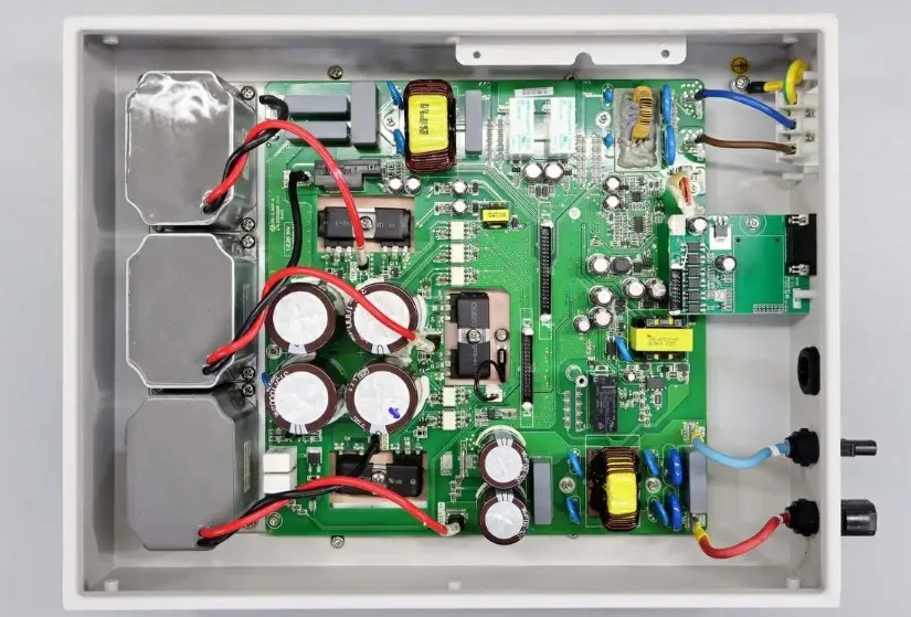
The assembly of solar PV and inverter PCBAs is similar to other energy PCBAs in that they include power conversion, sensing, and environmental protection requirements. However, when assembling a solar charge controller, early reviews will be needed on the protective coatings and coating keep-out zones to ensure connector reliability, thermal paths, and access to appropriate test points for these controllers.
Energy Storage BMS Assembly
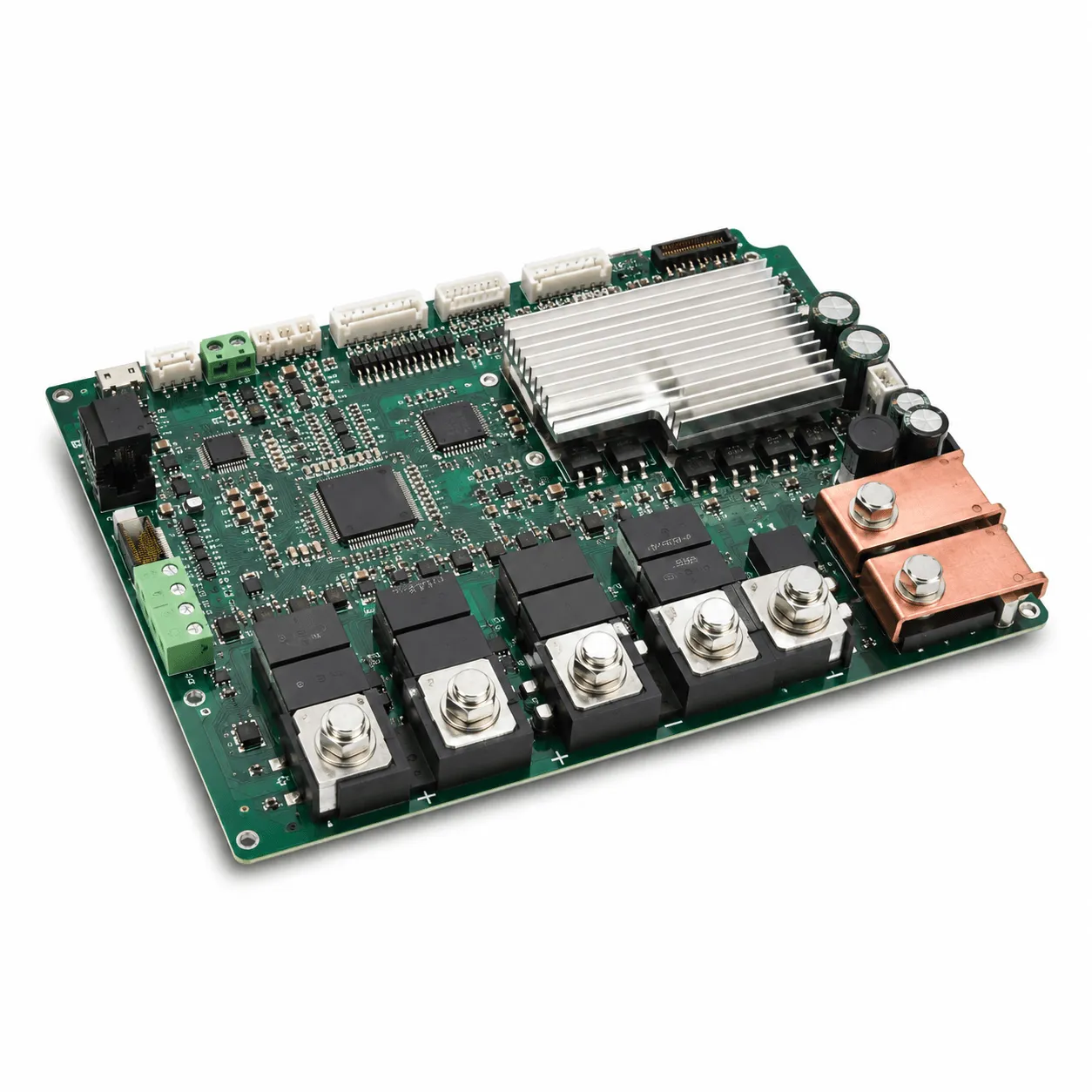
The manufacturing process for energy storage BMS assemblies consists of battery monitoring and balancing, battery sensing and protection, and BMS control. A BMS includes a control board that processes the input received from the battery cells, monitors and manages charge and discharge functions, provides a response to faults, and facilitates communication of that information between the BMS and the user. The quote for portable power station PCBAs or supercapacitors should reflect the stresses on the connectors, firmware loading capabilities, and current paths.
EV Charger Control PCBA
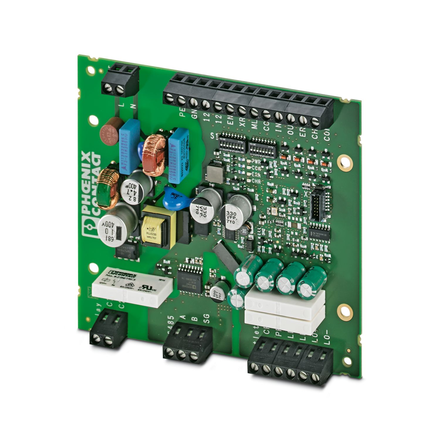
EV charging and motor controller PCBAs must support power switching, communication, isolation, and long operating cycles. Powertrain control boards have the same need for communication and isolation under long operating cycles. The PCBA may also require CAN/LIN, EMI filtering, heavy copper traces, high-voltage isolation, and reliable connector soldering.
Wind Turbine Control PCBA
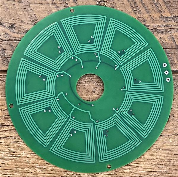
Wind turbine converter board assembly and wind turbine condition monitoring board assembly face vibration, humidity, power cycling, and remote maintenance pressure. The focus for assembly should be on connector strength, conformal coating coverage, sensor interface soldering, communication modules, and inspection documentation. A PCBA that works properly on a bench setup can still fail if vibration, moisture, or test access is not planned for the use environment.
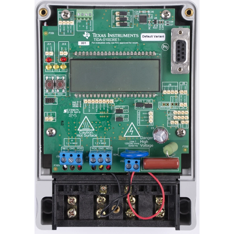
Smart Meter And Grid Monitoring
Smart grid and microgrid controller PCBAs combine measurement, communication, isolation, and control into the same PCBA. Smart meter and energy monitoring boards typically require stable signal paths, mechanically and electrically secure connectors, firmware loading, and traceability documentation.
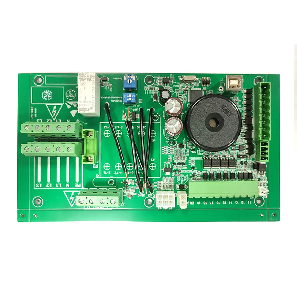
Power Conversion PCBA
Power supply, UPS, DAQ, and distribution boards put different levels of pressure on current paths, heat dissipation, component isolation, and connector design. Power assembly should also include a review of heavy parts, solder volume, thermal transfer, creepage distance, and final power-up verification.
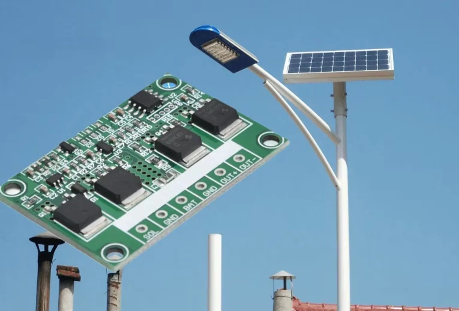
Outdoor Lighting Controller PCBA
LED lighting and solar street lighting PCBAs are typically subjected to heat, moisture, dust, UV exposure, and repeated power cycling. The assembly plan should consider aluminum-core or metal-core options, coating limits, cable connections, driver performance, and burn-in or environmental screening. A small outdoor controller can fail quickly if the protection step blocks heat dissipation or leaves connectors exposed.
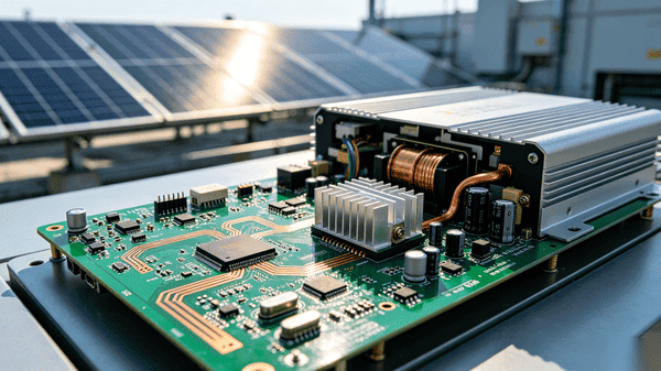
Renewable Energy Control Systems
Controls for hydropower, geothermal, biomass, ocean energy, fuel cells, and heat pumps are very different in design and performance, but they share one purchasing problem: application conditions affect assembly risk. Humidity, vibration, thermal cycling, chemical exposure, and continuous operation all affect material selection, coating, connectors, firmware loading, and inspection depth.
Hydropower and ocean energy controls are typically found in wet, corrosive environments; therefore, connector sealing and conformal coating adhesion can have as much impact on circuit performance as circuit design.
Geothermal and biomass control boards are typically designed to operate in warm ambient conditions for extended periods, so the PCBA review should lean more toward thermal derating and solder-joint fatigue than raw power rating.
The operating environment and anticipated service life should be expressed in the file package so that the assembly plan, along with the schematic, corresponds with the site condition.
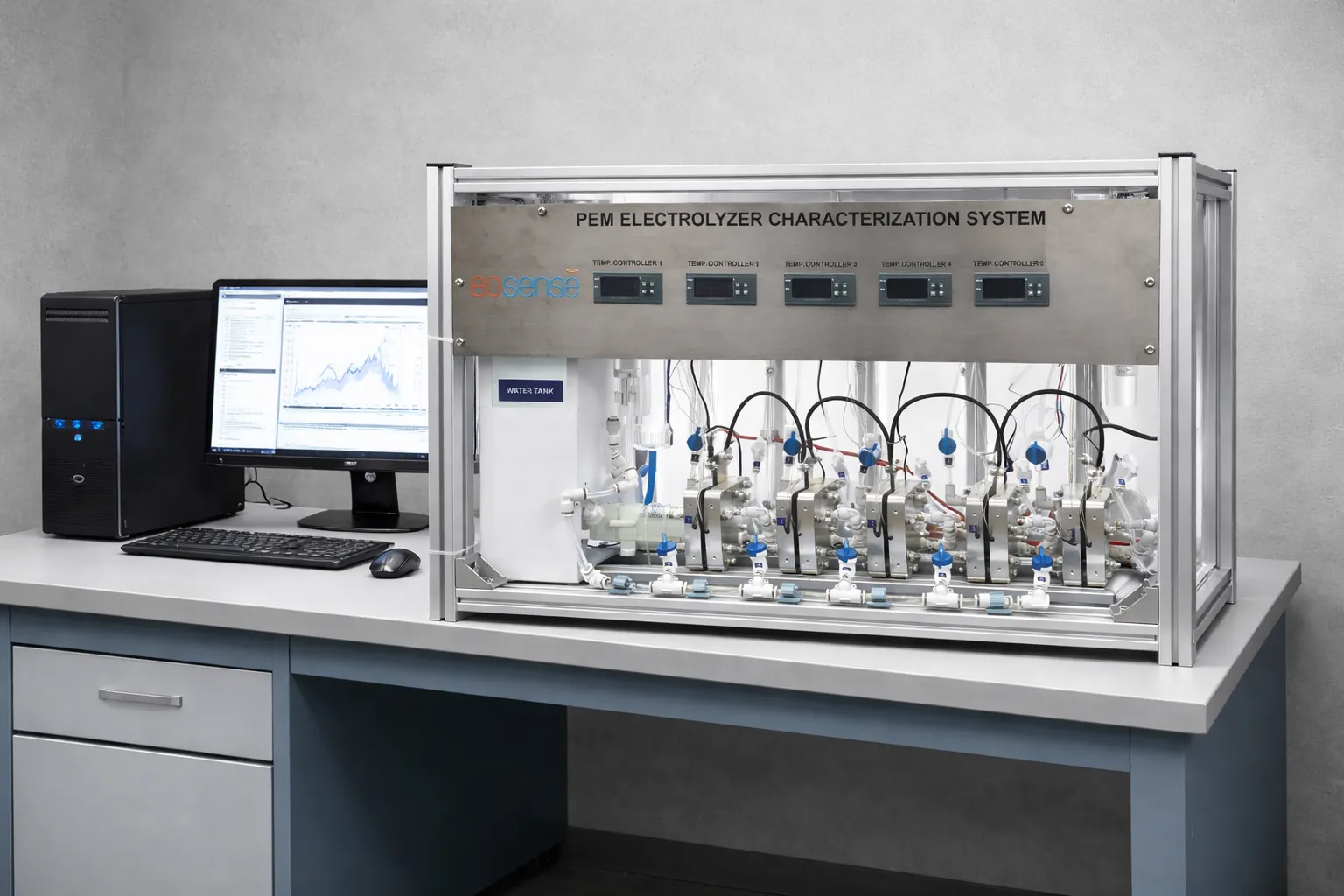
Hydrogen Electrolyzer Control PCBA
Hydrogen electrolyzer control PCBA fits the same power-and-control boundary as other energy equipment. The hydrogen electrolyzer control PCBA may include current sensing circuits, fluid-system control signals, communication controls, coating, and functional testing.
Hydrogen electrolyzers work by passing high current through electrodes at a relatively low operating voltage. Therefore, during the assembly review process, the design engineer should confirm the busbar and connector capacity in addition to trace and via size.
Because most hydrogen electrolyzer control boards are located close to hydrogen gas and moisture, coating keep-out zones, connector sealing, and corrosion-resistant finishes need the same early review as outdoor solar or wind-powered installations.
Before shipping a control PCBA board, functional testing should also confirm fluid-system interlocks and sensor signal paths, because a wiring or calibration fault in those signals carries a higher safety consequence than in a typical control circuit.
Files For A Clear Quote
An accurate quote can be generated when suppliers can see the board, the parts to be assembled, their arrangement on the PCB, and the testing burden.
Gerber and BOM are the foundation of energy PCB quotes; however, energy PCB assembly often also needs PnP data, drawings, stencil notes, fixture requirements, firmware status, and kitting rules. If the supplier has to estimate these additional items, the quote may include assumptions that later change cost or delivery.
Missing kitting information and stencil notes can also transfer costs from an identified line item to an assumed line item; therefore, quote changes typically originate from this area.
| Checklist item | Why it matters | If missing | Result affected |
|---|---|---|---|
| Gerber files | Defines PCB layers, drill, fabrication and panel data | Fabrication and assembly quote can be inaccurate | PCB fabrication and stencil planning |
| BOM with MPN and AVL | Drives sourcing, shortage checks, and cost | Alternates and lead time may shift | Component sourcing and quote timing |
| Test specification | Defines ICT, FCT, fixture, acceptance criteria | Test cost and schedule may change later | Test plan and final validation |
Testing Energy PCBAs
When testing the functionality of an assembled PCBA for energy applications, testing should simulate actual product functionality. Optical inspection is used for visible placement and soldering defects. X-ray inspection can be performed on solder joints and hidden solder connections. ICT, FCT, power testing, programming, and assembly testing help verify proper operation. Environmental testing, endurance tests, burn-in testing, and HALT can only be conducted when the use case justifies the extra stress.
| Quality action | Main risk found | Best-fit energy board | Record |
|---|---|---|---|
| SPI / AOI / visual inspection | Placement, polarity, visible solder defects | All SMT/THT energy PCBA | 100% AOI inspection record |
| X-ray | Hidden solder joints and BGA voids | BGA, micro BGA, power modules | X-ray report or image when specified |
| Environmental and HALT tests | Thermal, UV, humidity, vibration weakness | Outdoor solar, wind, EV charger, street lighting | Environmental or HALT report |
Functional Testing And Programming
Functional testing, test programs, power testing, programming tests, and other electrical tests may be performed using the manufacturing fixture. Use of the manufacturing fixture will depend on PCB manufacturing drawings and conformity to the manufacturer's design. ICT can verify the electrical points where the manufacturing fixture connects to the PCBs. FCT verifies that the PCBs meet corresponding functional requirements with respect to defined outcomes or performance expectations. Testing through power-up can uncover manufacturing issues that are only visible once the product has received power, while firmware is loaded during programming before final compliance testing. Each test performed requires the following items to be effective: a fixture to hold the product, firmware, a defined set of pass/fail standards, and predefined fail paths.
Test Records You Can Review
Validate the test records for the suppliers you wish to consider, along with their compliance documentation, so you can determine if their processes and procedures are compliant with the industry standards for the target market. For example, ISO 9001:2015, ISO 13485:2016, ISO 14001:2015, IATF 16949, RoHS, REACH, UL, and SGS records should reference the certificate scope. The importance of these documents may increase significantly when your electrical product needs to be safe to use within the target market based on the requirements outlined within IEC 61010. Be sure that the test records provide complete details describing what products were tested, whether they passed, whether they failed, and what final record will accompany the completed PCBA.
Compare Energy PCBA Suppliers
| What to Check | Question to Ask | Details to Prepare | What It Confirms |
|---|---|---|---|
| Application coverage | Has the supplier handled the same energy equipment family? | Application, voltage/current, environment, lifecycle | Confirms application fit |
| Engineering and capacity fit | Does capacity match the board’s voltage, current, layer, and volume needs? | Voltage/current class, layer count, monthly volume | Confirms production fit |
| Testing and compliance | Can the supplier show tests and required documents? | Test spec, target market, certificate requirement | Confirms test and document fit |
| Lead time and volume fit | Does timing match BOM, quantity, and test depth? | Quantity, BOM availability, delivery plan | Sets realistic quote expectations |
Check The Factory Fit
Before placing your order for a PCB assembly, verify that the factory has sufficient capacity to produce the quantity that you will order based on the types of assemblies that will be produced, such as SMT, DIP, THT, and their respective placement speeds. This also applies if they will produce multiple types of assemblies.
Lead Time Depends On The Details
The time frame to complete the assembly will depend on the quantity ordered and the complexity of the assembly design. For example, a simple standard prototype assembly may be completed in as little as 24 hours, while an assembly-only job can take 5 days, and full turnkey sourcing and assembly typically takes approximately 10-15 days, depending on component availability. Your specific quantities and assembly specifications, such as the BOM, along with the methods used to protect the final assemblies during shipment, will provide you with an estimated time for delivery of all completed products.
FAQ
Yes, energy PCB assembly can support custom renewable energy projects, including layouts and component types, based on specifications provided by customers before quoting for an assembly. The application, environment, class/type of voltage/current, and acceptance criteria must also be provided to determine whether the project is considered a prototype, low-volume assembly, or production assembly.
The time it will take to complete the assembly will depend on the availability of the components needed to manufacture, assemble, and test the final products; see the lead-time details above for typical prototype, assembly-only, and turnkey timeframes.
Use the Files For A Clear Quote checklist for the required files to accompany your quote request. In addition to the required files, be sure to provide all environmental attributes of your assembly, such as class/type of voltage/current, coatings, physical condition of the enclosure, final destination, and acceptance criteria for your assembly.