Upload BOM & Gerber

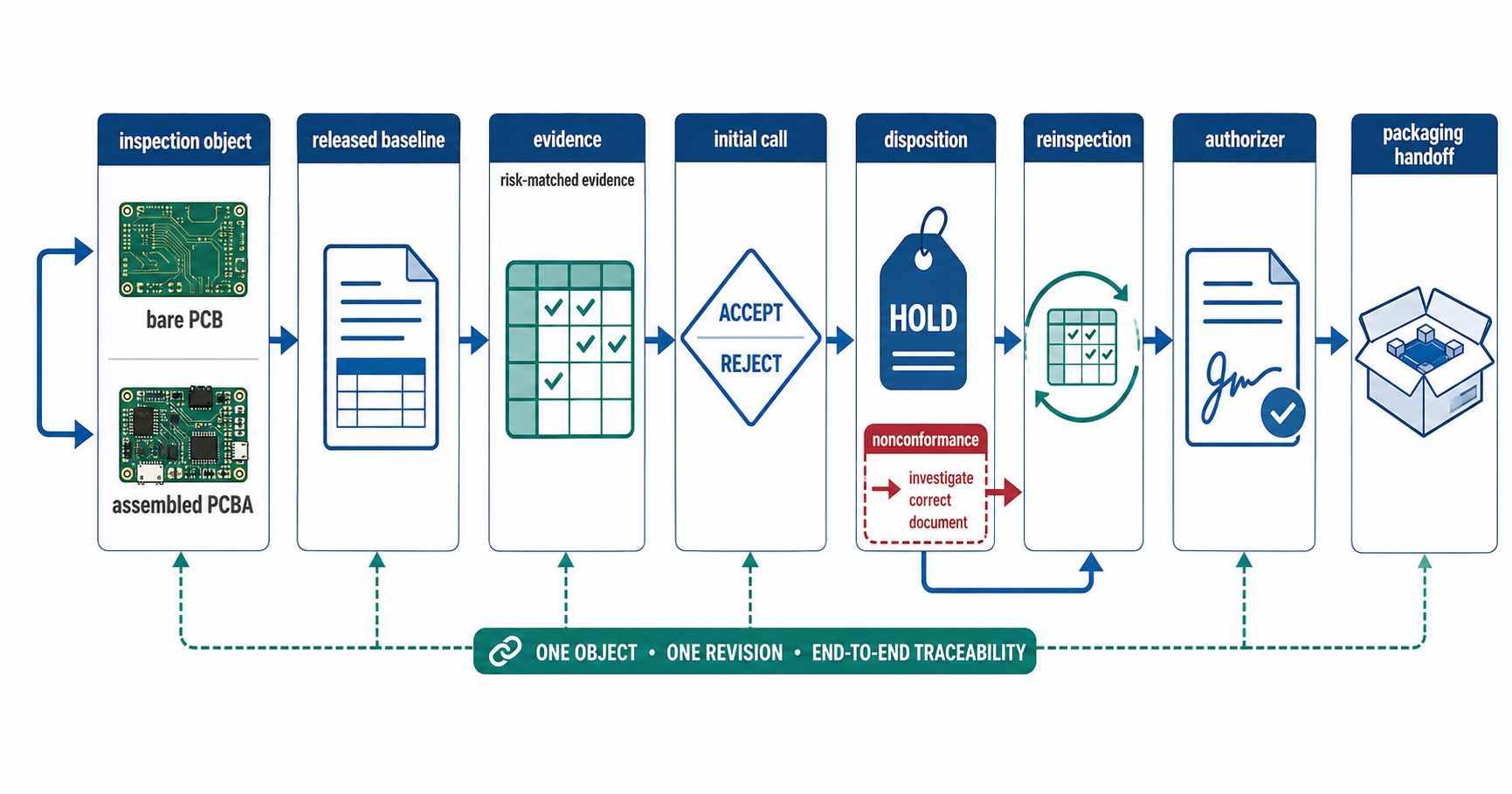
In practice, FQC represents the last QC gate of the named finished object; it does not define one machine or suggest every risk has been assessed. Each gate only compares the actual board or assembly to an approved baseline; the outcome record shows any failure along with authorized release, hold, or rejection decisions. However, if we cannot trace the lot, revision, criteria, test limits, and earlier failures, the clean PASS holds no value.
The generic build process for PCBs does not resolve the release question. Those that want to follow the average assembly sequence should reference PCB Fundamentals. The more direct chain is: identify the object, secure the baseline, map risks to evidence, maintain the initial call and disposition, authorize release, then protect the approved condition for shipment.
Contents
show
FQC Inspection Is a Release Decision, Not a Machine
FQC determines if the finished PCB or PCBA is free to leave the final product control gate. Tools such as visual inspection, AOI, X-ray, electrical tests, and functional tests can all be used to inform FQC decisions; however, no single tool defines the gate. A report that simply states “Board: PASS” reflects a potential compliance gap during a customer audit or field return investigation, when nobody can determine what drawing revision, test limits, or past failure history the PASS was based upon. Local plans must also identify whether a separate OQC or OQA gate controls the shipment.
FQC is an output-based QC process within a broader quality system. ISO defines QA as a preventive and process-based system, and QC measures output against the requirements in a specification (Quality Assurance: A Critical Ingredient for Organizational Success). The quality system provides document control, trained roles to perform the quality checks, measurement tools, and authority for decision-making. FQC uses these elements to perform inspection on a finished product. FQC inspectors use the released rules from the quality plan to record the results of inspections or measurements and to stop or segregate any products found to be suspect. The quality plan must define who holds the authority to change limits, to accept an unapproved deviation, or to release the product for shipment. An inspection that is performed perfectly based on the wrong revision will release an incorrect product.
Are You Releasing a Bare PCB or an Assembled PCBA?
While the final checks for Bare PCBs and Assembled PCBAs may appear similar in function, the characteristics that are acceptable differ. Submitting a mixed checklist for completed checks can cause the product state to be identified incorrectly.
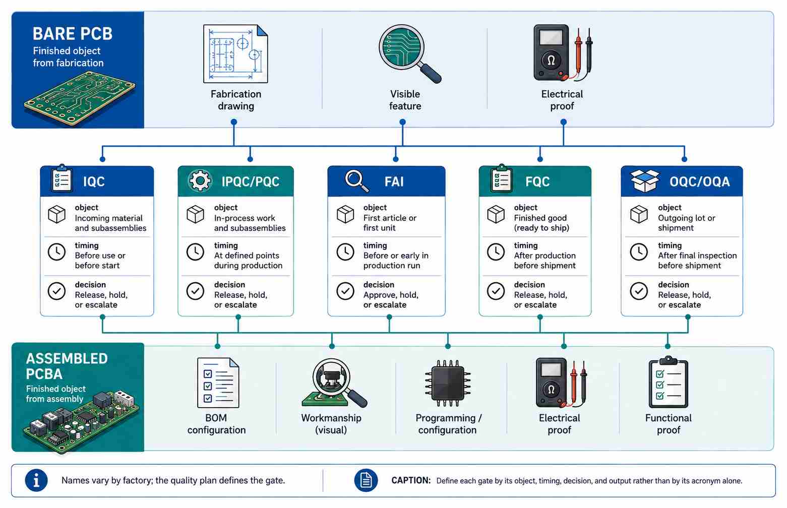
For Bare PCBs, the released fabrication drawing and specifications determine the acceptable dimensions, surface features, holes, conductors, markings, and applicable electrical proof requirements. IPC defines IPC-A-600 as the acceptability document for Bare PCBs (Certifications in Electronics Manufacturing). The current public revision table lists IPC-A-600M, but the contract must define which revision of IPC-A-600 applies (IPC Document Revision Table). The Assembled PCBA includes the following: assembly build configuration; the presence of fitted or not fitted (DNP) parts; part identification and value; orientation of parts; solder quality and workmanship; programming state; electrical behavior; functional value and labeling of the assembly. The soldering process and material requirements for PCBAs are defined by J-STD-001J. The acceptability of electronic assemblies is defined by IPC-A-610J. IPC describes these as two complementary documents (IPC Releases “J” Revisions to Two Leading Standards for Electronics Assembly). Neither document is a replacement for the authorized engineering drawings, customer additions, product class, or test specification.
The typical criteria for final inspection of bare boards include outline dimensions, hole and slot features, warpage or flatness when specified, solder mask and legend condition, exposed finish or gold fingers, contamination, and obvious surface damage. The typical visible criteria for final inspection of assembled boards include part identity/value; Fitted/DNP; polarity of parts; orientation of parts; connector alignment; visible solder bridges or insufficient solder; Tombstoning; contamination/residue/foreign bodies; labeling; and handling damage. Each inspection call is based on the current released fabrication drawing, contract criteria, or approved documented limits rather than an arbitrary tolerance used by an unrelated factory.
A common source of confusion regarding release records is gate nomenclature: site operations that allow incoming inspection to sign off under the FQC gate, or sites that allow IPQC to issue a release, create confusion regarding decision authority that is appropriate to a different stage of the production process. The stages of the production process are not interchangeable, even when multiple stages are being performed by a single person.
Factory labels vary by site; the same gate could be designated as FQC, final inspection, or product acceptance at different facilities.
The first article inspection covers the complete first-build task. FQC begins only after the object being manufactured has reached its approved final state and all required upstream evidence is available.
Which Inputs Control the Final Checklist?
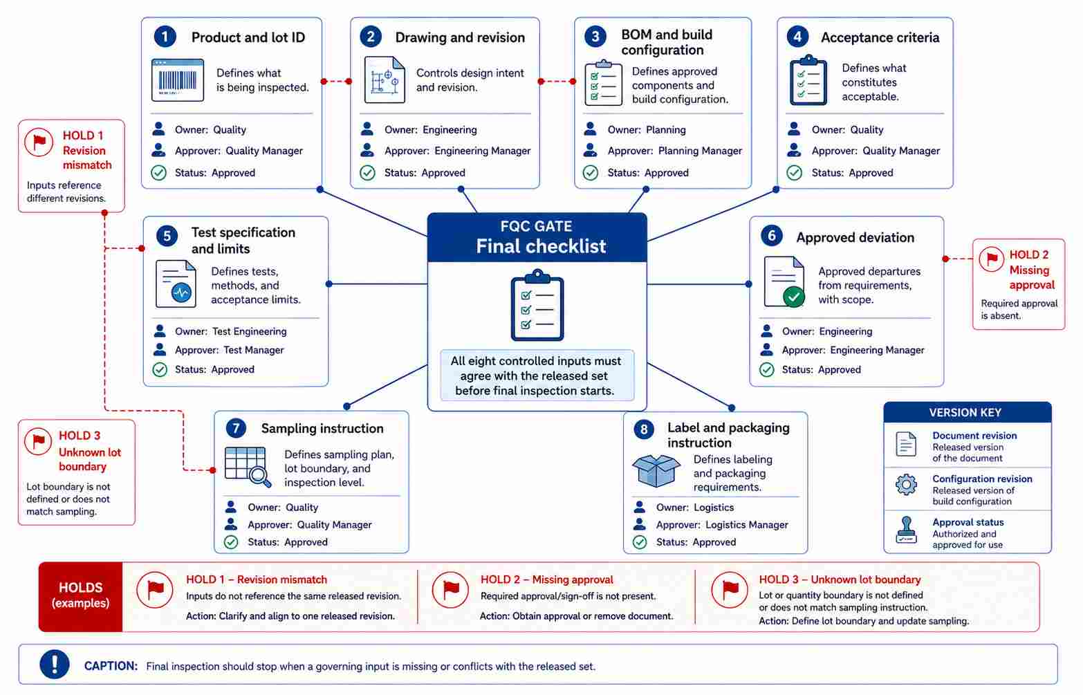
If there are discrepancies between two quality and product inputs, if there is no quality or product limit identified, if there is no approval for deviation from the specifications, or if the lot boundary is currently unknown, then all work must be held until the input is resolved. An inspector should never create an additional requirement to keep a lot moving.
ISO 2859-1:2026 contains guidelines for AQL-indexed lot-by-lot acceptance sampling schemes. The AQL-indexed lot-by-lot acceptance sampling scheme includes single, double, multiple, and skip-lot plans with switching rules. An AQL of 2.5 used with a lot size, inspection level, inspection state, and sampling scheme allows for the definition of a specific acceptance sampling plan, but does not mean that each lot will contain 2.5% defective units. Records must show the inputs needed to reproduce this acceptance sampling plan, the corresponding sample size, and the acceptance or rejection numbers.
A 100 percent check will show that all units received an inspection using the specified inspection method and criteria; however, it will not show whether that same inspection method can identify all defects, whether any functions that were not inspected will work, or whether the inspected product will perform over time. To determine which inspection method covers the relevant risk, you need to match the coverage with the risk associated with the product. As of August 21, 2026, ISO 9001:2015 is the most current published edition. ISO/FDIS 9001 has been approved, and ISO states that it anticipates publishing the sixth edition of ISO 9001 on September 16, 2026. Until the sixth edition is available, ISO 9001:2015 is the current published standard; once the new edition becomes available, you should review the applicable version.
How Do You Match Each Risk to the Right Evidence?
Beginning with the machine list and working backward reverses the logic for establishing the appropriate inspection method. Therefore, methods such as AOI, visual inspection, X-ray inspection, electrical testing, and functional testing support specific decisions based on the types of risks identified in your process. No single inspection or test result proves complete product conformity.
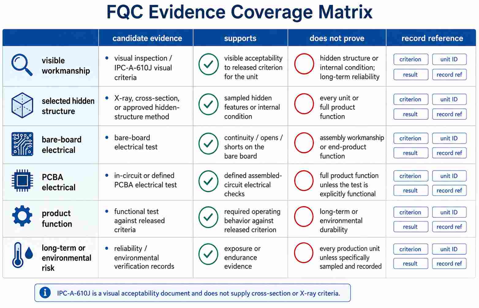
The table of contents of IPC-A-610J is very specific about visual quality acceptability for electronic assemblies. It does not include criteria for cross-section or X-ray acceptance. In addition, any repair, modification, or change to a product requires its own authorization under the contract and quality system — IPC-A-610J does not provide authorization on its own.
Guidance that is specific to a method provides information on the inspection capabilities of the method, but the FQC record must be able to tie that method to the unit, its revision, its criterion, and the result of the inspection.
What Must the Report Preserve After a Failure?
In the event of failure, the FQC report must retain the first objective result from the original inspection and the auditable authority chain; do not overwrite a failed call with a subsequent PASS call. ISO provides guidance on how to document these records for the purpose of verifying the conformity of products with the acceptance criteria and providing traceability back to the individual who authorized the release of the goods. For nonconforming output, the retained information shall contain information relating to the nonconformity, the action taken to correct it, any concession, and the authority that approved the action.
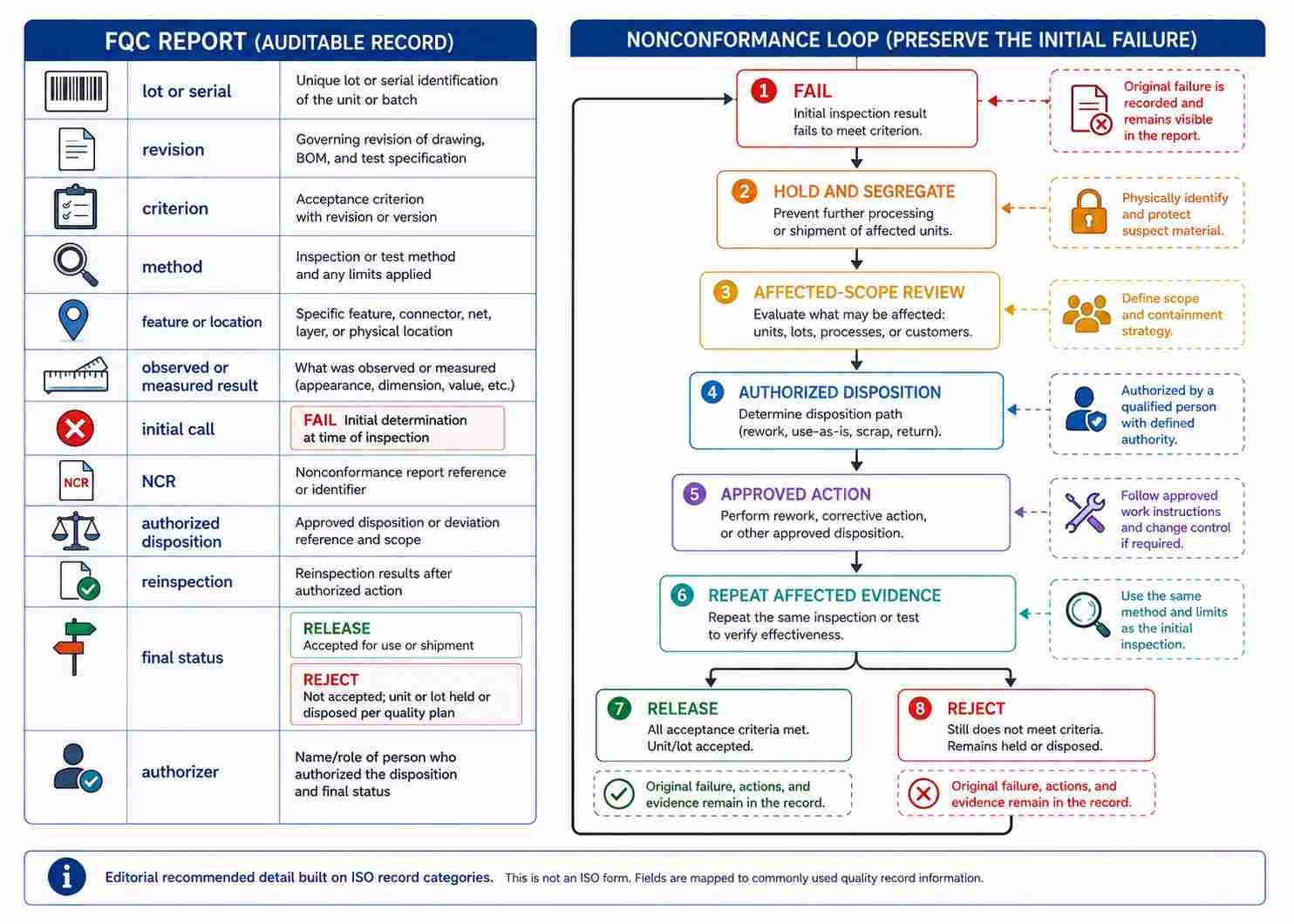
Consider a record that kept only the last PASS and disregarded the first FAIL and all rework completed in between. An auditor or a subsequent failure investigation would have no way of knowing whether that unit actually shipped clean the first time or if it just passed after the rework was completed — which is an important distinction for warranty claims or patterns of repeated failures.
The steps include containing and segregating the suspected output, identifying and documenting the scope of the impacted area, creating or linking the NCR, and obtaining an authorized disposition from the site’s named authority, such as the MRB where the quality system uses one. Once approved, appropriate means will be used to correct, rework, repair, scrap, return, or apply a concession as applicable. Then repeat the evidence affected by the approved action and record the reinspection result before release or rejection.
Describing a failure at final inspection and identifying how the failure occurred are two separate functions, since a final inspection may include identifying a design discrepancy, a bare-board defect, an assembly anomaly, a test-setup error, or damage due to subsequent handling. The inspection record alone will not identify the source of the failure, so it is essential to retain the history of configurations, inspections, processes, tests, and reinspections to determine the detection point of the failure from where the failure originated. The IPC-1782B document describes the scope of manufacturing and supply-chain traceability for electronic products, but no universal report format exists.
Example: A Failed Functional Test That Later Passes Reinspection
The released customer functional test specification may indicate that a nominal 5.00 V rail shall be tested at ±5%, or 4.75 to 5.25 V. Unit SN-0147 measured 4.72 V, therefore receiving an initial “FAIL” status. The FQC department held the unit and documented the issuance of an NCR. Following authorized rework of the unit, the original failed test was conducted again, resulting in a measurement of 5.01 V. Both measurements, 4.72 V and 5.01 V, are documented, as well as the version of the test program utilized to arrive at both results, the action taken and its disposition, the reinspection result, and who authorized the final disposition of the product. The 5 V example illustrated here does not represent an industry-wide FQC tolerance; actual decisions will be driven by the customer’s own test specifications related to the product being shipped.
From Product Acceptance to Shipment Release
After product acceptance, verify that the product’s identity and physical condition as accepted will remain intact throughout the packaging handoff process. The work performed by the packaging department is downstream of the decision to pass the acceptance process for the product — packaging protects the accepted product and maintains the labels and records through the packaging and shipment stages, including whether the same authority chain reaches shipment.
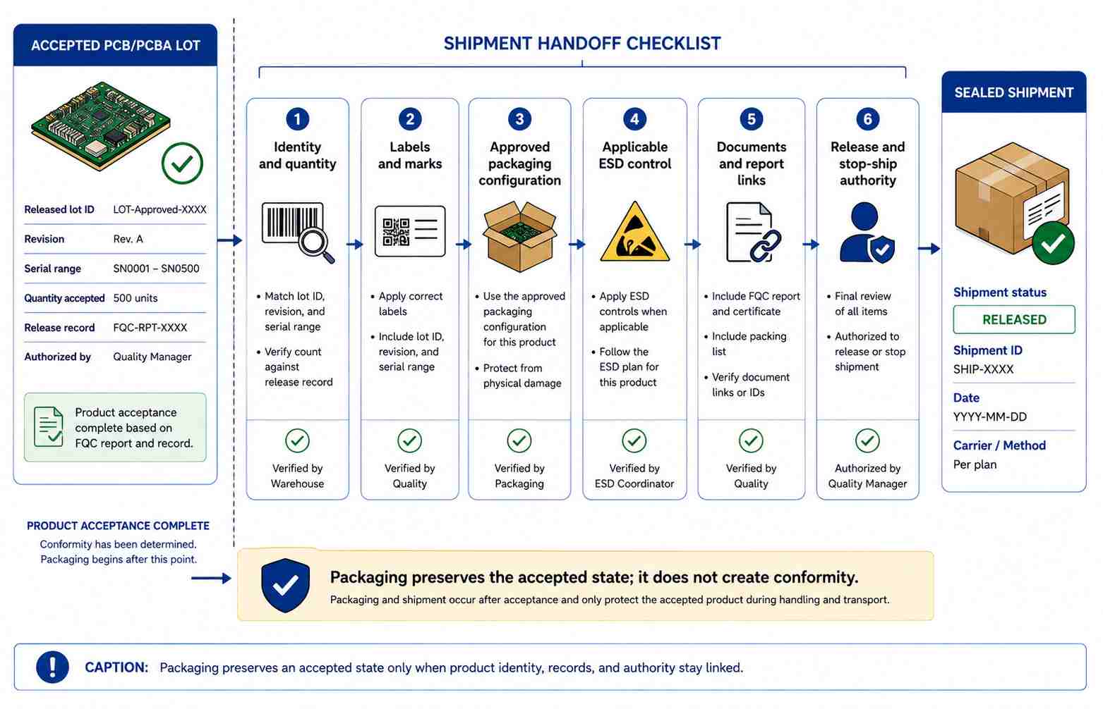
ANSI/ESD S541-2026 establishes requirements related to packaging of ESDS products throughout production, transport, and storage. This document does not establish one universal packaging configuration for every PCB or PCBA; desiccants, vacuum bags, humidity limitations, and moisture barriers may be utilized differently depending upon the product, customer’s requirements, material, and established ESD control plan. If there are separate OQC or OQA gates in place within the factory, identify what the FQC department will provide for transfer as well as who is responsible for making the ultimate “stop-ship” decision. If there is a single person fulfilling both roles, the product acceptance and the shipment handoff must be clearly documented separately in the records.
Prior to accepting the phrase “FQC included” as meaning “FQC was performed,” obtain the governing criteria and revision, coverage map, sample report, test limits, failure and disposition path, record-retention rule, and release authority. These documents allow comparisons between PCB and PCBA inspection capabilities while separating the service list from the release system. A shipment is release-ready only when the accepted item, associated evidence, and protective handoff of that item are in agreement as to identity and authority.
References & Sources
- Quality Assurance: A Critical Ingredient for Organizational Success – International Organization for Standardization
- Certifications in Electronics Manufacturing – Global Electronics Association
- IPC Document Revision Table – Global Electronics Association
- IPC Releases “J” Revisions to Two Leading Standards for Electronics Assembly – Global Electronics Association
- ISO 2859-1:2026 – International Organization for Standardization
- ISO 9001:2015 – International Organization for Standardization
- ISO 9001 revision update – ISO/TC 176/SC 2
- IPC-A-610J – Global Electronics Association
- Guidance on the Requirements for Documented Information of ISO 9001:2015 – International Organization for Standardization (ISO)
- IPC-1782B – Global Electronics Association
- ANSI/ESD S541-2026 – EOS/ESD Association
- Final quality control | How to make a PCB step 11.3 – NCAB Group