Upload BOM & Gerber

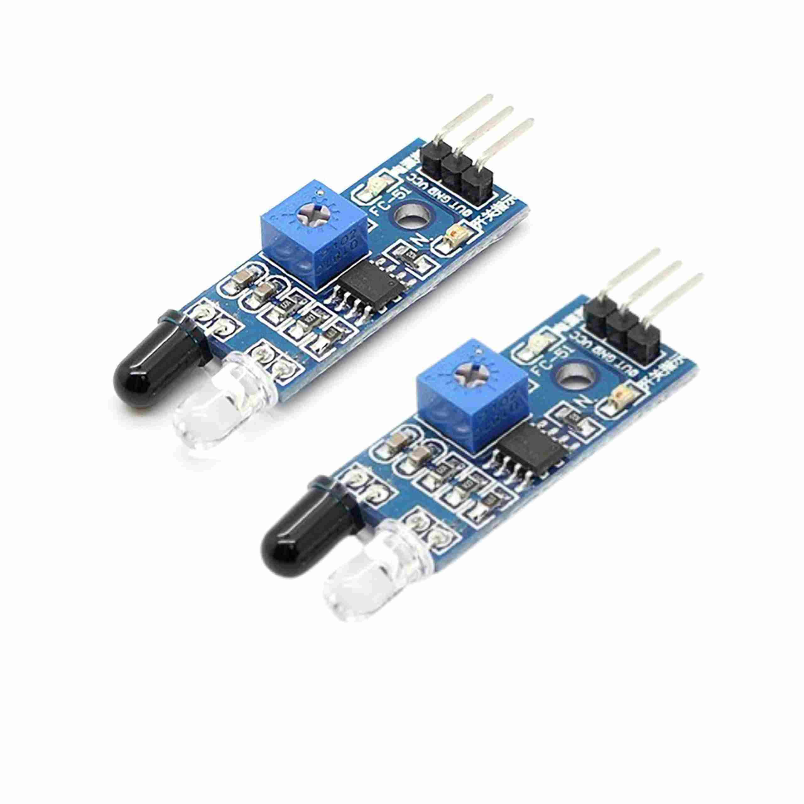
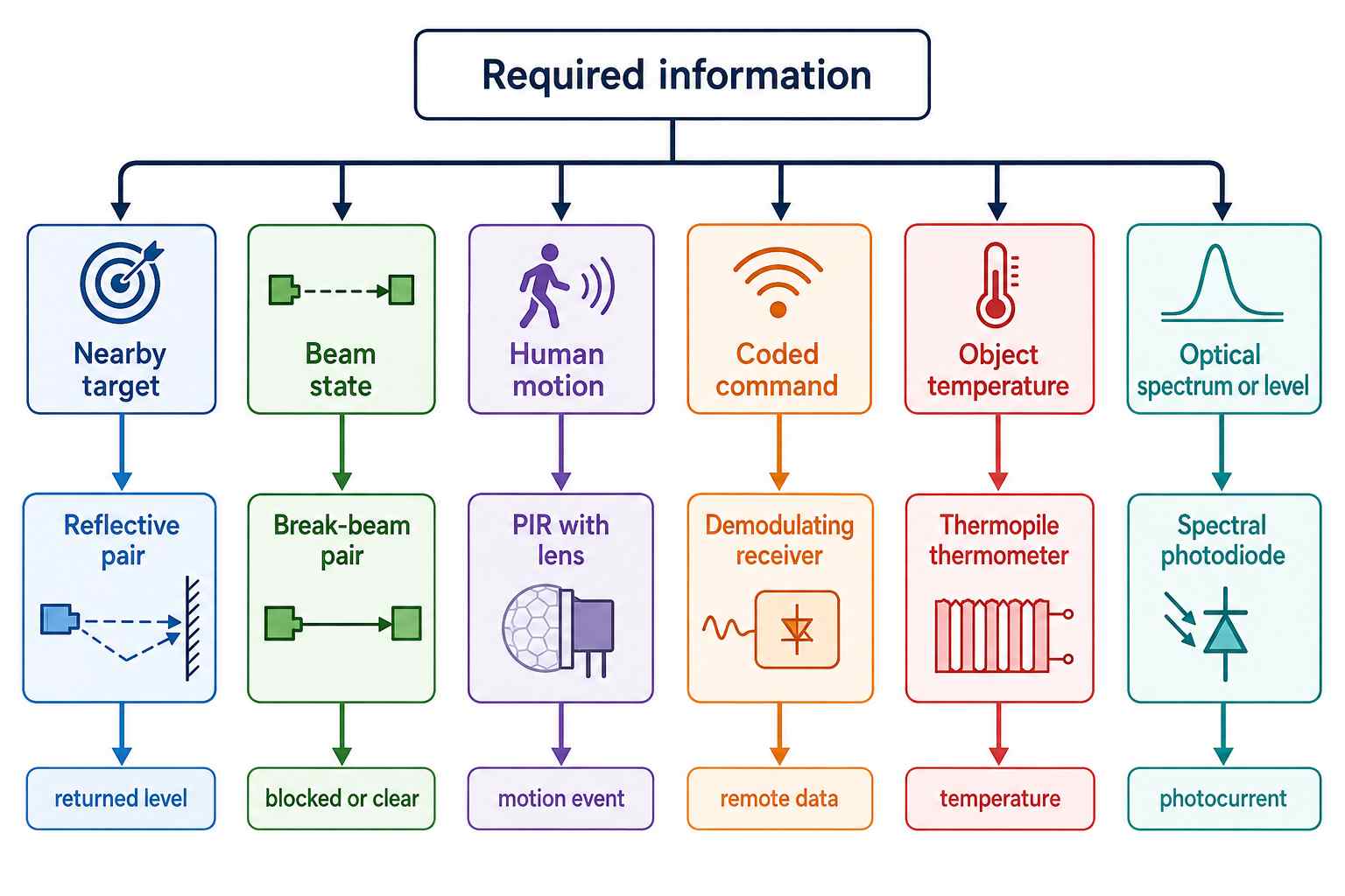
IR sensors are specialized devices that detect infrared radiation associated with specific events or measurements. While IR sensors respond to infrared radiation within the range of roughly 700 nm to 1 mm, different sensing architectures are used for different tasks. Thus, while the term “IR sensor” covers a wide range of sensing technologies, it does not mean that one type of IR sensor can replace another. For example, reflective sensors indicate the presence of nearby objects, break-beam sensors indicate when the beam path is interrupted, PIR sensors indicate movement, remote-control demodulators recover remote-control data, and thermopiles indicate the temperature of an object. These types of outputs are not interchangeable, and there is no single useful answer to questions about the range, voltage, pin order, accuracy, or interface of IR sensors.
To select the IR sensing device for your circuit design, you should consider what information your circuit will require to function correctly before beginning the design process. After defining the information needed by the circuit, you can begin to determine which architecture you want to implement, which device you want to use, how to connect the device to the optical path, how to interface with the device, how to operate the device in your application environment, and how to validate that your IR design will work as intended outside of a controlled laboratory test.
- The infrared spectrum ranges from approximately 700 nm to 1 mm; the sub-bands of light are identified and referred to in various ways by those who work with this technology.
- Infrared sensors can use one of several types of sensing technology, including reflective sensors, PIR sensors, demodulating receivers, thermal sensors, and other sensing technologies.
- IR sensors for individual circuits in practical use can vary with respect to their range, voltage, pin order, accuracy, or interface; no single answer provides the correct information for all users.
- Prior to finalizing any design, the user must validate the characteristics of the target material, ambient light, geometry, optical window or lens, temperature, and timing of any firmware associated with the selected IR sensor.
Contents
show
What Is an IR Sensor?
Infrared wavelengths extend past the visible red spectrum and include wavelengths that fall within the range of approximately 700 nm to 1 mm. Different industries define the boundaries of near-, short-wave-, mid-wave-, and long-wave IR bands differently, so when discussing or using a specific IR band, it is important to clarify which convention or device specification is being used.
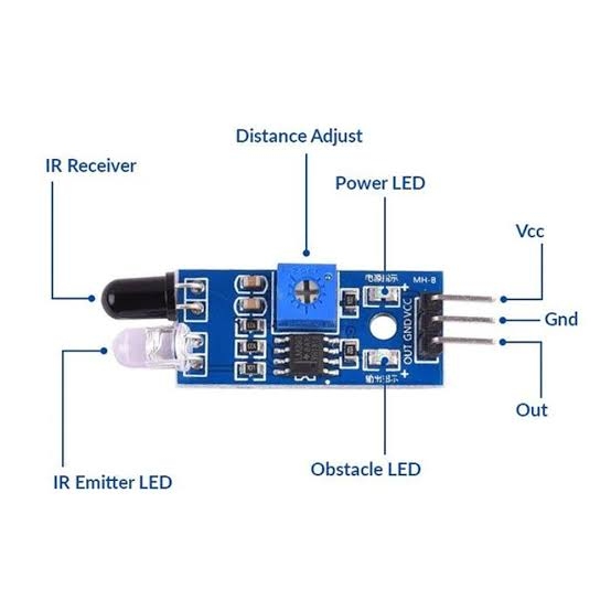
The term IR sensor refers to a family of devices and not to a specific configuration, package, or circuit. While some IR devices sense reflected near-infrared light, others detect changes in thermal radiation; some IR sensors are used to recover modulated communication signals; and others measure optical power over a range of wavelengths. So, rather than attempting to determine “Which IR Sensor is Best?” it may be more useful to ask “What information will my system require?”
How Does an IR Sensor Work?
All IR sensing devices have an optical path between a source of infrared radiation and a detector; however, the source of the IR radiation does not necessarily belong to the sensor itself. Once you understand active IR sensing and passive sensing independently, the IR signal path becomes easier to comprehend.
Active IR Sensing
In all active IR systems, there is a local emitter. The chain of events in a typical active IR system is an IR emitter, a target or optical path, a detector, analog processing or demodulation, and a threshold, processor, or digital interface. In reflective sensing applications, the emitted IR is reflected by a nearby target and received by the detector. In break-beam systems, the emitted signal propagates across a defined path and is interrupted when that path is blocked.
A remote-control link operates with an emitter and detector pair, where a modulated carrier signal is sent from an emitter/transmitter to the detector/receiver. As they are part of the same measurement chain, increasing the current supplied to the emitter does not linearly increase the effective range. A more powerful emitter still may not work if the receiver is saturated, the target reflects poorly, there is too much ambient sunlight, there is attenuation of the wavelength through a lens or window, or the return geometry prevents sufficient energy from reaching the detector.
Passive IR Sensing
Passive IR does not require an active emitter. Passive IR systems utilize IR radiation from the object or scene and focus this energy through a lens, window, or filter onto the detector. In a PIR sensor, the response to changes in thermal energy within defined regions is used primarily for motion or occupancy detection. Thermopile detectors provide an alternative means of measuring thermal radiation, permitting non-contact temperature measurements. However, the properties of the materials, wavelengths, optical power, and noise conditions determine the response of spectral detectors.
What Are the Main Parts of an IR Sensing System?
In general, an IR system’s functions depend on the type of architecture utilized; however, many of the functions identified in this section are common across a variety of IR sensing applications. While a product may not contain every function listed, and ready-made modules may combine multiple functions into a single package, the following functions recur across many IR systems:
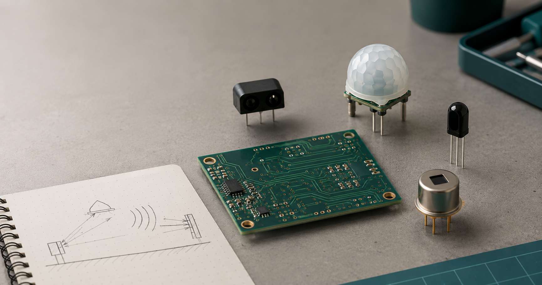
- Emitter, when required: An IR LED or some other energy source provides controlled optical energy for active IR sensing or communication.
- Optical Path: The lenses, apertures, windows, filters, surfaces of the targets being viewed, and mechanical spacing between them determine the radiation that will be received by the detector.
- Detector: A photodiode, phototransistor, pyroelectric sensor, thermopile, or another type of detector will convert the energy received into a measurable electrical signal.
- Analog Front End: The detector may require bias, transimpedance gain, filtering, amplification, and conversion of the raw signal.
- Decision/Processing: A detector’s output may go through processing methods including a comparator, AGC, demodulation, ADC, DSP, or μC.
- Interface: The result may appear as one or more types of signals corresponding to what has been detected, such as analog voltage, a thresholded logic output, demodulated logic, serial communications via I2C or SMBus, PWM, or another device-specific interface.
Active vs Passive IR Sensors
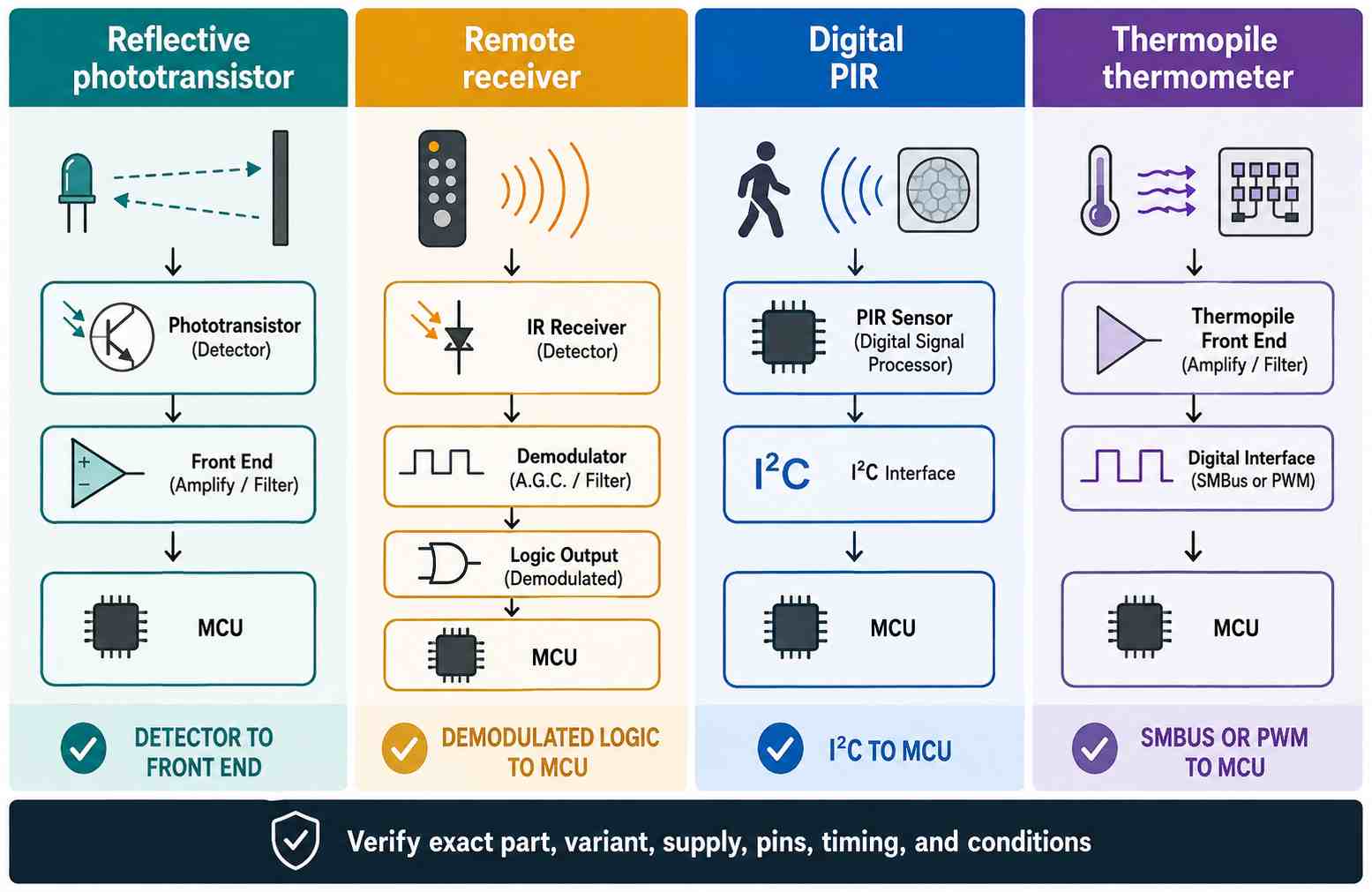
Active versus passive is only the first architecture split.
How Do the Main IR Sensor Types Differ?
Reflective IR Sensors
Reflective infrared sensors send infrared light towards an object and measure how much infrared light gets reflected back to the sensor. There are many factors affecting the results of a reflective sensor: the target’s surface color, finish, angle, the size of the target, the amount of emitter current being used, the bias on the detector, the distance between the sensor and the object being detected, and ambient light at the site of the detection.
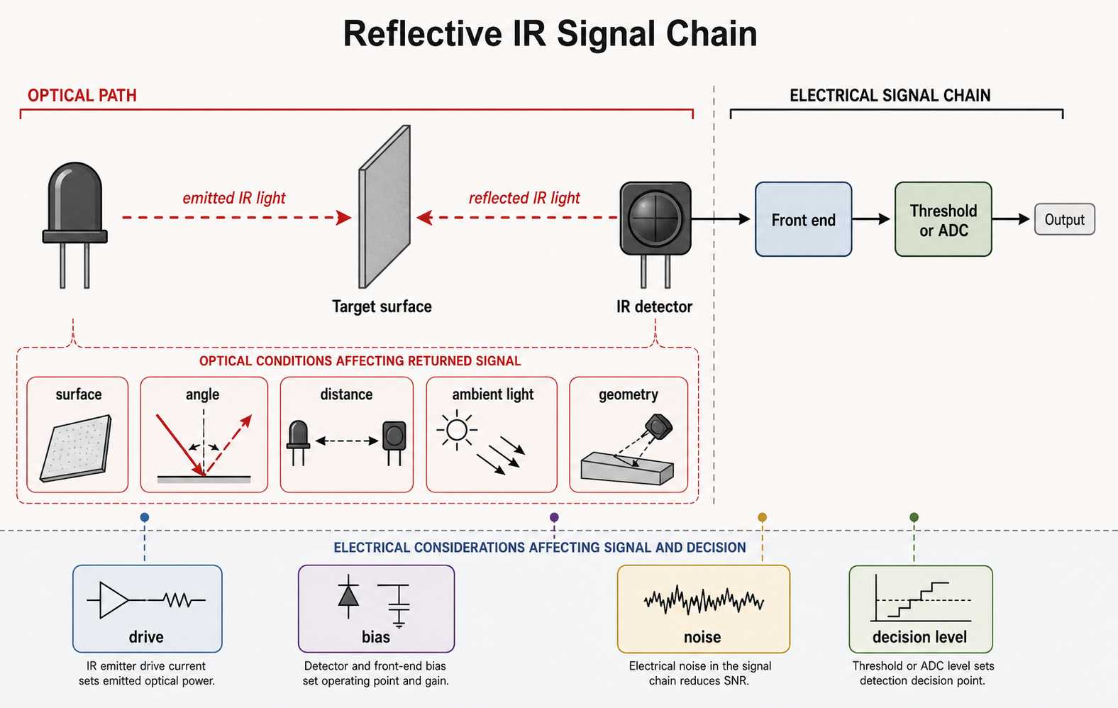
A device such as Vishay’s TCRT5000 combines an IR emitter and phototransistor in one small reflective package, with a focus on use in short-range proximity applications. This design has a peak response only millimeters away from the sensor’s face. As a result, the TCRT5000 is widely used in edge detectors, encoder wheels, and small object-presence switches, which are intended for proximity detection.
Break-Beam Sensors
The definition of a break-beam detector is an infrared sensor where the emitter and receiver are located on opposite sides of the infrared path that is being monitored. The receiver determines whether or not the path is blocked. A break-beam detector is less dependent on target surface reflectivity than a reflective IR sensor because the receiver detects whether the optical path is interrupted rather than measuring reflected energy. However, with break-beam sensors, users must be concerned about proper alignment tolerance, aperture size, vibration, dust, contamination, and adequate receiver margin.
A design that relies on parts being aligned by hand can ultimately fail due to the shifting of the beam after enclosure tolerances or mechanical movement. An example of the scale at which this can occur can be seen with Omron’s EE-SX1103; it is a through-hole transmissive photointerruptor with the following specifications: a slot width of 2 mm, phototransistor output, response time of 10 microseconds, and rated for -25 °C to 85 °C. The slot width is a key geometric constraint in the alignment budget, and the keep-out region, tolerance stack-up, and how the part will be mounted must be dealt with around the slot width prior to fixing the enclosure layout, not as an adjustment after the fact on the bench.
PIR Sensors
PIR sensors detect changes in the amount of thermal radiation received by the sensor. To achieve this, normally a lens will divide the field of view into multiple zones, where movement across these zones will cause a detectable change in the sensor’s response. Therefore, PIR sensors are mostly used for detecting motion and occupancy. Some of the key system parameters for determining how PIR sensors work include the lens pattern, height of the sensor, the angle of the mounting, the timing for the detection, as well as the thermal background and other sources of heat near the sensor. The way that a PIR is implemented today is not limited to just using analog modules; for example, Murata’s IRS-D series is a digital implementation with an I2C interface, and it is designed for detecting humans with an appropriate optical system.
IR Remote-Control Receivers
IR receivers operate as demodulating receivers, not as simple photodiodes. Vishay’s TSOP38438, for example, combines a detector, multiple gain stages, filtering, AGC, and demodulation before sending the logic to a processing unit. The TSOP38438 operates as a 38 kHz IR receiver, and its pin configuration is pin 1 = OUT, pin 2 = GND, and pin 3 = VS. This order of pins is specific to the TSOP38438 receiver and is not a standard for all three-pin IR receivers. Link margin is affected by the following parameters: carrier frequency, burst timing, emitter spectrum, ambient light, and supply disturbance.
Thermopile IR Sensors
The thermopile sensor converts absorbed infrared energy into a signal that is related to the temperature difference. The thermopile and IC can be combined to create a complete thermopile sensor IC with a digital interface. The Melexis MLX90614 integrates a thermopile and signal-processing ASIC in a TO-39 package. The Melexis MLX90614 supports contactless temperature measurement, but the reading is highly influenced by everything that falls inside the field of view. As a result, the emissivity of a target, target fill, optical window design, and thermal gradient are critical to the measured temperature. Digital resolution is also important but is not the only factor when performing accurate non-contact temperature measurement.
Spectral Photodiodes and SWIR Detectors
Spectral sensing requires a detector material or optical system specifically tailored to the intended spectral wavelength. The usable spectral windows for silicon, InGaAs, and other detector families are not the same. As an example, Marktech has published usable spectral windows for InGaAs photodiode families at 600 nm to 1750 nm or 800 nm to 2600 nm, based on the specific device. Spectroscopy, optical measurement, and gas analysis devices use these detectors in applications to analyze light from specific wavelengths, and general proximity modules are not suitable substitutes.
IR Sensor vs IR LED
An IR LED is an infrared emitter; it emits infrared radiation when connected to an electrical power supply. An IR sensor or infrared detector responds to infrared radiation or infers information regarding an event associated with IR radiation. IR sensors can work with active reflective systems that contain an IR LED to illuminate the target and an IR detector to measure the reflected radiation. In passive PIR or thermopile sensors, there is no local source of IR light—the source of incoming IR radiation is the scene or target itself. By using the terms ‘IR LED’ and ‘IR sensor’ interchangeably, this difference is obscured.
Are IR Sensors Analog or Digital?
In terms of analog vs. digital, IR sensors can produce either type of output based on the level of signal conditioning they have incorporated. For example, a raw photodiode generates a photocurrent, which is an analog signal, and typically needs to be connected to an analog front end to develop an appropriately conditioned output. A phototransistor can be biased such that its optical response is converted into a varying voltage. A breakout module may include a comparator circuit to generate an active HIGH/LOW output at a particular threshold defined by the user. A remote-control receiver, which demodulates the modulated output of an infrared transmitter, will provide demodulated logic. Digital PIRs can communicate via I2C; thermal sensor ICs such as the MLX90614 can provide SMBus data or PWM.
The exact type of interface used on the IR sensor will be detailed in the manufacturer’s device documentation, so it should never be assumed based solely on identifying it as an ‘IR sensor’.
Does an IR Sensor Have a Standard Pinout?
IR sensors do not have standardized pinouts. Several educational reflective modules may use common VCC, GND, and OUT pin connections, but this is simply the convention of that particular module and should not be considered representative of IR sensors overall. For example, a three-pin TSOP38438 will use OUT, GND, and VS in that specific configuration; while a raw photodiode may expose only the two detector terminals; a digital PIR may require both an input power connection along with I2C communications; and a thermal sensor IC may use either a communication bus like I2C or SMBus, or an output such as PWM. Also be aware that packages are oriented differently, and suffixes differ from manufacturer to manufacturer, so it is always best to verify the correct pin functions as specified by the manufacturer’s particular package drawing and pin function table prior to capturing a schematic diagram or physically assembling the IR sensor.
IR Sensor Range, Accuracy, and Field of View
There is no single range, accuracy, or field-of-view specification that applies to all IR sensors. Each type of IR sensor has specifications that depend on defined conditions, as discussed below.
The reflective range of an IR sensor depends on emitter drive, target surface, target geometry, receiver threshold, and ambient light levels. An IR remote-control receiver’s effective range depends on the transmitter, carrier frequency, burst patterns, receiver sensitivity, angle of incidence, and interference from ambient light sources. Thermal sensors will vary according to target fill, target emissivity, package temperature, and calibration conditions. Therefore, the correct number will always be the number attached to that specific IR sensor along with the conditions under which it was measured.
Representative IR Sensor Specifications
How to Read an IR Sensor Datasheet
Think of all specifications as statements that define a specific product under specific parameters and conditions for each number. This allows you to avoid reusing a current-limit or distance curve or a field-of-view diagram in situations where it may not be relevant to the current evaluation.
Emitter specifications should also be properly defined. The documentation for Vishay’s TSAL6200 IR emitter clearly defines continuous, pulsed, duty-cycle, and thermal specifications for this 940 nm IR emitter. An absolute maximum specification indicates a boundary rather than a recommended operating condition. Determining the type of driver should be accomplished using the appropriate parameters, such as optical need, type of pulse pattern, ambient temperature, thermal characteristics, and verified specifications for the device rather than from a generic resistor calculation.
IR Sensor Applications
Proximity and Object Detection
Reflective IR sensing is commonly used for detecting the presence of objects at short distances, counting products, determining line or edge orientation, and providing a non-contact signal for simple robotics and other applications. An IR emitter illuminates a nearby target, and an IR detector is used to measure the reflected IR energy returned from the target. The limitation of reflective IR sensing is that the target forms part of the optical path. Different types of surfaces will absorb and reflect varying amounts of light energy; for example, matte surfaces, dark plastics, polished metals, curved surfaces, and angled labels can all produce different levels of return energy at the same distance.
Other light sources such as direct sunlight or a strong lamp source can reduce the IR receiver’s margin. A more robust design will validate several target finishes, target positions, and ambient-light conditions instead of just tuning one target threshold to one sample sitting on a desk.
Motion and Occupancy Detection
PIR sensors are widely used today for applications ranging from security detection to smart lighting systems, occupancy sensing, doorbells, thermostats, IP cameras, and many other low-power IoT devices. Unlike a ranging sensor, PIR sensors are not able to provide an absolute distance to a person; rather, they detect changes in infrared radiation as a person moves through predetermined zones created by the PIR lens.
Many factors will affect the detection of an individual by PIR sensors, including the mounting height of the sensor, the pattern created by the lens, the direction an individual is walking, detection timing, the background temperature, and the presence of other heat sources in the area surrounding the sensor. Murata lists doorbells, thermostats, smart lighting, and IP cameras as applications for its IRS-D series. The PIR sensor must be validated with the final lens and enclosure; if validated alone, it could produce an inaccurate estimate of coverage.
Remote Control and IR Communication
The IR remote-control communication link consists of two components: first, the transmitter; second, the receiver. The transmitter modulates an infrared carrier to carry information. The receiver rejects much of the steady ambient background light while recovering the burst pattern from the infrared carrier. Some companies that manufacture consumer-oriented IR remote-control receivers produce product families centered around a specific carrier frequency.
Since the output of the receiver is already demodulated to produce a logic-level output, treating the receiver like a raw photodiode will result in incorrect circuit design. The link margin depends on the radiant intensity of the transmitter, wavelength matching, carrier frequency, duty cycle, distance, angle, sunlight and artificial-light interference, and supply quality. The firmware must decode the protocol and timing that the transmitter and receiver are using instead of simply sampling an undefined analog signal.
Non-Contact Temperature Measurement
Thermopile IR sensors provide a means for non-contact temperature measurements in monitoring equipment, appliances, industrial control, and any other situation in which it is not desired or practical to come into contact with the measurement target. The MLX90614 is a good example of the difference between specification-sheet figures and actual measurements; fine digital resolution does not necessarily equate to measurement accuracy.
The sensor averages the infrared radiation received from within its field of view. The accuracy of the measurement is affected by thermal equilibrium, the amount of target fill, the emissivity of the target, optical transmission, and the temperature gradient across the detector package. A small hot target surrounded by a cooler background may give a different result from a target that fills the field of view because the sensor also receives radiation from the surrounding background.
Spectroscopy, Gas Analysis, and SWIR Detection
Spectroscopy and non-dispersive infrared gas analysis are examples of using wavelength-dependent absorption to identify or quantify materials, and flame detection and optical measurement may be focused on specific spectral regions of the infrared. The configuration of the detector, filter, source, and optical path is critical to ensure that they are all matched to the wavelength of interest.
InGaAs photodiodes are normally used for applications in the near-infrared and short-wave infrared; the standard near-IR window covers water and hydrocarbon overtone bands, which is why moisture measurement, food sorting, and plastics identification are commonly carried out in that spectral region, while extended-response InGaAs photodiodes reach further into the SWIR band for some gas-analysis applications and low-light imaging. Additionally, parameters including the detector’s spectral response, dark current, active area, bandwidth, source spectrum, filter transmission, and signal-to-noise ratio become more important than the simple VCC/GND/OUT connection scheme used by reflective modules.
Advantages and Limitations of IR Sensors
How Should an IR Sensor Be Integrated into a PCB?
PCB integration has to manage the connection of electrical interfaces with both the optical path and mechanical path. Correct symbols or footprints cannot mitigate a blocked field of view, reflective enclosure walls, receiver saturation, noise in the power supply, or a hot component placed adjacent to a thermal sensor.
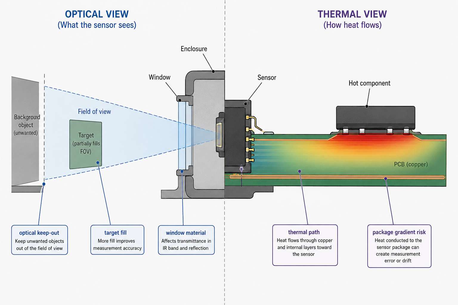
Ambient rejection, carrier matching, filtering, threshold logic, and firmware form one signal chain. Stronger emission cannot compensate for a poor optical window, specular reflection, receiver saturation, or bad geometry. Expose a signal before the final firmware decision, such as the raw output of the detector, diagnostic count, or receiver state, where practical so testing can distinguish an optical problem from a threshold or timing problem.
Thermal placement requires a separate review. Melexis states that the accuracy conditions of the MLX90614 assume thermal equilibrium and an isothermal package. The presence of hot electronics, heaters, coolers, or a nearby hot object can create temperature gradients and thus affect the accuracy of the measurement. The field-of-view cone and the heat paths around the device must also be part of the placement discussion.
SUGA-PCBA PCB Design Service Overview outlines the major design inputs that must be defined before proceeding to layout and manufacturing reviews.
How Do Ambient Light, Target Material, and Temperature Affect IR Sensors?
These environmental factors must be defined prior to selecting final thresholds.
Reflective sensors will exhibit different performance characteristics based on the reflectivity of the target material, the angle of incidence on the target material, the degree of gloss of the target material’s surface, and the level of ambient IR present.
Break-beam systems typically have a lower dependence on the optical finish of the object, but they can lose margin due to contamination and misalignment.
Passive infrared sensors depend on the thermal contrast between the object and its environment and the motion of the object through the zones of the lens.
Remote receivers can be disrupted by incompatible carrier timing, strong ambient sources of IR, and ripple or noise in the power supplied to the device.
Thermopile-based measurements may also be affected by the fill of the field of view, the emissivity of the object, the transmission characteristics of the optical cover medium, and thermal gradients around the package.
The optical cover must have its own set of test conditions. A medium that appears transparent to the eye may attenuate or reflect the IR wavelength used by the detector. Coatings on the cover, gaps, dirt and condensation on the cover, and internal reflections from adjacent surfaces will affect the IR signal. It is important to validate the final material and geometry of the optical cover used and make no assumptions that bench testing performed on an uncovered sensor represents the finished product.
How Should an IR Sensor Be Tested?
To ensure that the IR sensor functions correctly, testing should be performed under a range of conditions that represent those that will be encountered in the actual application. Normally, a bench response is measured under a single set of conditions, such as in one room.
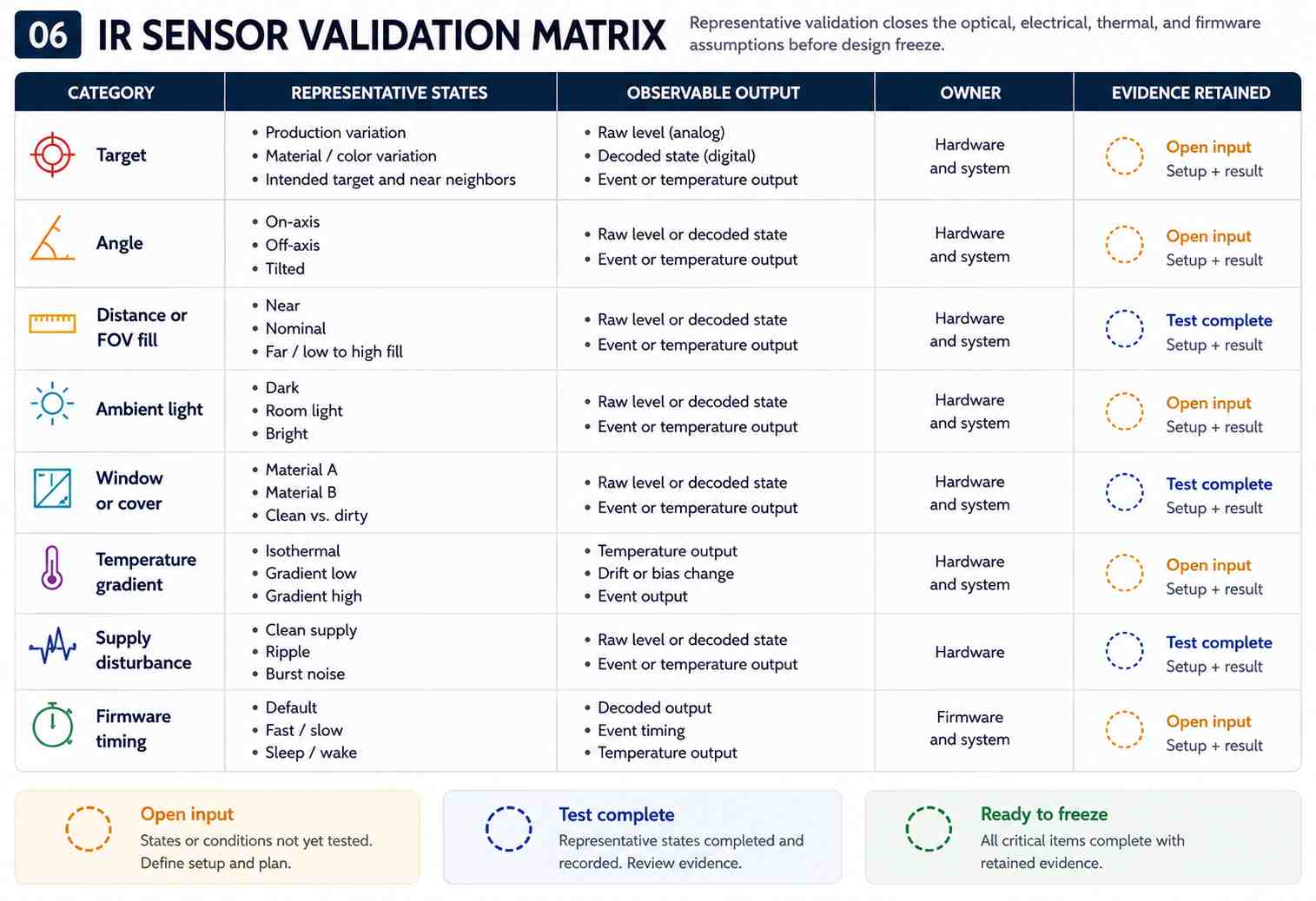
It is important to have a method of documenting how much margin exists before the final pass/fail threshold and to test the variables that may differ in the real product.
Calibration can compensate for a known and consistent relationship; however, it cannot convert a motion detector into a distance-measuring device, nor can it restore optical data that is blocked by the enclosure of the device. To reproduce the sensing decision after a component, housing, or firmware change, fixture dimensions, relevant raw traces, firmware settings, device revision, and representative test results must be retained.
If you have a circuit board that currently has an unrecognized detector or module installed, you should begin by identifying the exact part. Use the SUGA-PCBA guide to identifying circuit-board components to do this using methods for component confirmation, including part markings, package clues, and datasheet confirmation.
Frequently Asked Questions
Q1. Can an IR sensor detect through walls?
Do not assume that a generic infrared sensor can detect through a wall. The ability to transmit through a wall depends on the wavelength of the infrared light, the material and thickness of the wall, the technology of the detector, the power of the source, and the sensing method employed. The most common types of near-IR reflective modules and PIR motion sensors are constructed so that their optical path is directed into the scene rather than through ordinary opaque wall materials. To make a transmission claim, it is necessary to reference the specific wavelength and material instead of just “infrared.”
Q2. Does sunlight affect IR sensors?
Yes, the sun can affect infrared sensors in a variety of ways. Sunlight contains infrared radiation that can increase the background level of the detector, reduce the margin of the reflective sensor, or cause the detector to reach saturation. The impact that sunlight has on an infrared detector is affected by the spectrum of the detector, any optical filtering applied to the detector, modulation, the design and geometry of the receiver, and the strategy used for determining the threshold.
Remote-control receivers may utilize carrier filtering and AGC to improve rejection; however, these still have defined ambient and burst conditions. Therefore, it is essential to test under representative outdoor and indoor lighting conditions instead of simply assuming that dark-room results will transfer unchanged outdoors.
Q3. Can an IR sensor measure distance?
Certain IR systems may be capable of estimating or measuring distance; however, not all IR sensor types provide specific distance information. Most reflective proximity detectors provide a level of output that also varies according to target reflectivity and geometry. PIR sensors detect motion rather than distance, whereas break-beam sensors provide information on whether a path is blocked. Distance can only be claimed where the chosen system architecture and components have been designed and calibrated to provide that information under specific conditions.
Q4. Is a PIR sensor the same as an IR sensor?
A PIR sensor is an example of an IR sensor, but it is not synonymous with all IR sensors. PIR devices are passive, working by detecting changes in thermal radiation; they are most commonly used for motion or occupancy sensing. In addition to PIRs, reflective proximity sensors, IR remote receivers, thermopiles, and spectral photodiodes all operate using infrared radiation to achieve different purposes and employ differing interfaces.
Q5. What is the range of an IR sensor?
There is no universal range for IR devices. For example, according to Vishay’s TCRT5000 product datasheet, the peak operating distance for the reflective sensor is 2.5 mm and the relative-output range is from 0.2 to 15 mm. For remote receivers, thermal sensors, or break-beam detectors, the definitions of useful distance are different. Always refer to the appropriate datasheet curve or test method and keep the target, emitter, receiver, geometry, ambient condition, and threshold associated with the stated number.
Conclusion
To achieve a reliable design, ensure you accurately correlate each headline value of an IR sensor to the corresponding sensor and test conditions. Verify the exact part number and pinout, evaluate the optical path and field of view, determine how ambient and thermal variations affect the sensor, expose useful diagnostics, and test representative target materials, cover types, temperatures, power-supply disturbances, and firmware configurations.
References & Sources
- Infrared Imaging (IR range approximately 700 nm to 1 mm) – NIST
- TCRT5000, TCRT5000L Reflective Optical Sensor datasheet – Vishay
- TSOP382 / TSOP384 IR Receiver Modules datasheet – Vishay
- TSAL6200 High Power Infrared Emitting Diode datasheet – Vishay
- IRS-D Series Pyroelectric Infrared Sensors – Murata
- MLX90614 Digital Non-Contact Infrared Thermometer – Melexis
- InGaAs PIN Photodiodes – Marktech Optoelectronics
- EE-SX1103 Transmissive Photomicrosensor – Omron
- Tutorial 15: Infrared Sensors | 2024 SSCS Arduino Contest – IEEE Solid-State Circuits Society (SSCS)