Upload BOM & Gerber

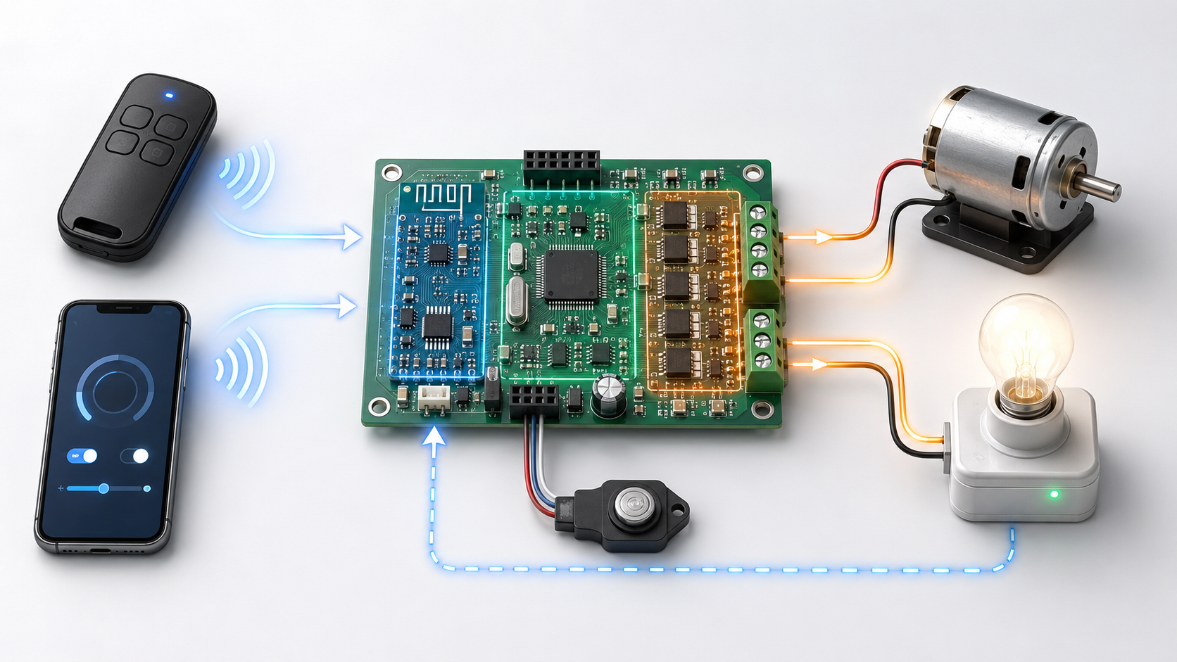
A remote controlled circuit enables control from a distant location by using signals sent by users to activate electrical equipment near the controlled device. The signals travel from the user to the controlled device through all the components included in the remote-controlled system—all the components needed to process signals from input to output. Some of these components allow the user to send signals; others allow the controlled devices to receive and execute those commands.
For example, say a remote-controlled circuit sends a command to start a small electric motor. When the electric motor receives the signal, that act alone does not confirm that the command is valid. Separate systems confirm that the command is valid, while other systems control how long the electric motor receives power.
- A remote-controlled circuit is an end-to-end command-to-load system, not one receiver or relay.
- Choose IR, proprietary or sub-GHz RF, Bluetooth LE, or Wi-Fi from operating conditions, not an advertised distance alone.
- Validate a command and define loss-of-signal, startup, and restoration behavior before output-state logic allows the load to change.
- Confirm command acceptance separately from physical load response, then repeat communication and driver tests with the actual load, final PCB, antenna position, enclosure, and intended environment.
Contents
show
What Is a Remote-Controlled Circuit?
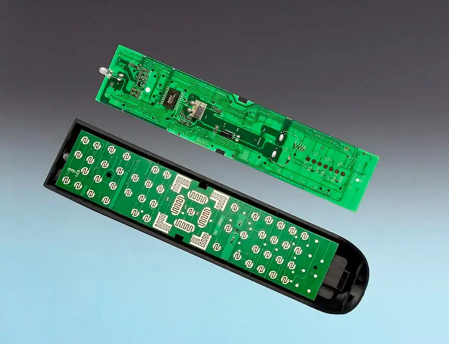
Remote-controlled circuits comprise all parts of the command path, including the method of communication, confirmation that the signal is valid, and determination of how and when the device should act on the command.
An end-to-end remote-controlled circuit includes many different parts, including the signal source, communication medium, command validation, state control, device driving, device power supply, and device feedback. Therefore, the presence of a signal on its own does not necessarily mean that the remote-controlled circuit is functioning properly. For example, a valid signal frame indicating that a command has been received might exist while no current is provided to the electric motor, the motor is jammed, the motor is disconnected from its circuit, or the motor is not in the commanded physical state.
TI’s reference material separates inputs, power, data processing (wireless engine), decision-making (logic), and output control (RF Smart Remote Control). This structure applies equally to IR and radio designs.
The definition does not depend on whether the connection uses wireless transmission. Remote control is defined by establishing an identifiable path between an input located far away and an action at the local site of the load. Radio and IR remove the direct physical wire between the input and the output.
A smart switch is a rated switching product, while a remote-operated circuit breaker combines a remote-operation mechanism with protective functions, ratings, status indicators, and installation requirements. A receiver board or general-purpose relay cannot be classified as a protective breaker merely because it can interrupt current flow to a load. Hazardous-voltage and distribution applications require products designed for safety and installation by trained, competent personnel.
How Does a Remote Command Reach the Load?
Remote commands reach loads by going through five functional steps. In cases where false activation or unsafe motion is possible, signal detection alone is not sufficient to authorize activation of the load, for example where an electrical shock hazard exists.
- Create and transmit the command: A remote command is generated and transmitted through IR or radio signals by a button, sensor, mobile application, or upstream controller.
- Receive and validate: The command is received by the receiver. The address and frame of the command, along with integrity and permitted-command checks, determine whether the command is valid and can be accepted by the receiver.
- Apply state logic: Hardware or firmware determines whether the command creates a momentary, toggled, latched, timed, or no output change.
- Drive and protect the load: The output stage provides the required voltage and current to the load while managing the startup demand, inductive energy, switching effects, and other load behavior.
- Confirm the result: Where feedback is required, the design should distinguish between command acceptance and actual load behavior, such as current, contact position, speed, or travel.
Command acceptance and physical feedback are not equivalent. Command acknowledgment should only confirm that a message was accepted. To confirm that the load actually changed, the design must include a current sensor, auxiliary contact, encoder, or position switch.
The Sub-1 GHz Wireless Motor Remote Control Reference Design separates transmission, reception, processing, power, and motor control. This separation of functions helps isolate whether a failure occurred in the communication link, decision logic, power stage, or load.
Before a load can be authorized, the validity of the command must be established. Vishay indicates that corrupted IR signals should be ignored (Data Formats for IR Remote Control). Receiving a carrier or radio packet can only confirm that data or messages arrived. It cannot guarantee that the command is valid, that the driver responded correctly, or that the load acted as required.
How Do You Choose IR, Proprietary RF, Bluetooth LE, or Wi-Fi?
Only after identifying the equipment, operating path, network needs, power budget, installation experience, interference levels, consequences of failure, and sales region can you choose the communication link. Advertised range alone is not sufficient because product effectiveness may also be influenced by antenna direction, enclosures, obstructions, and location.
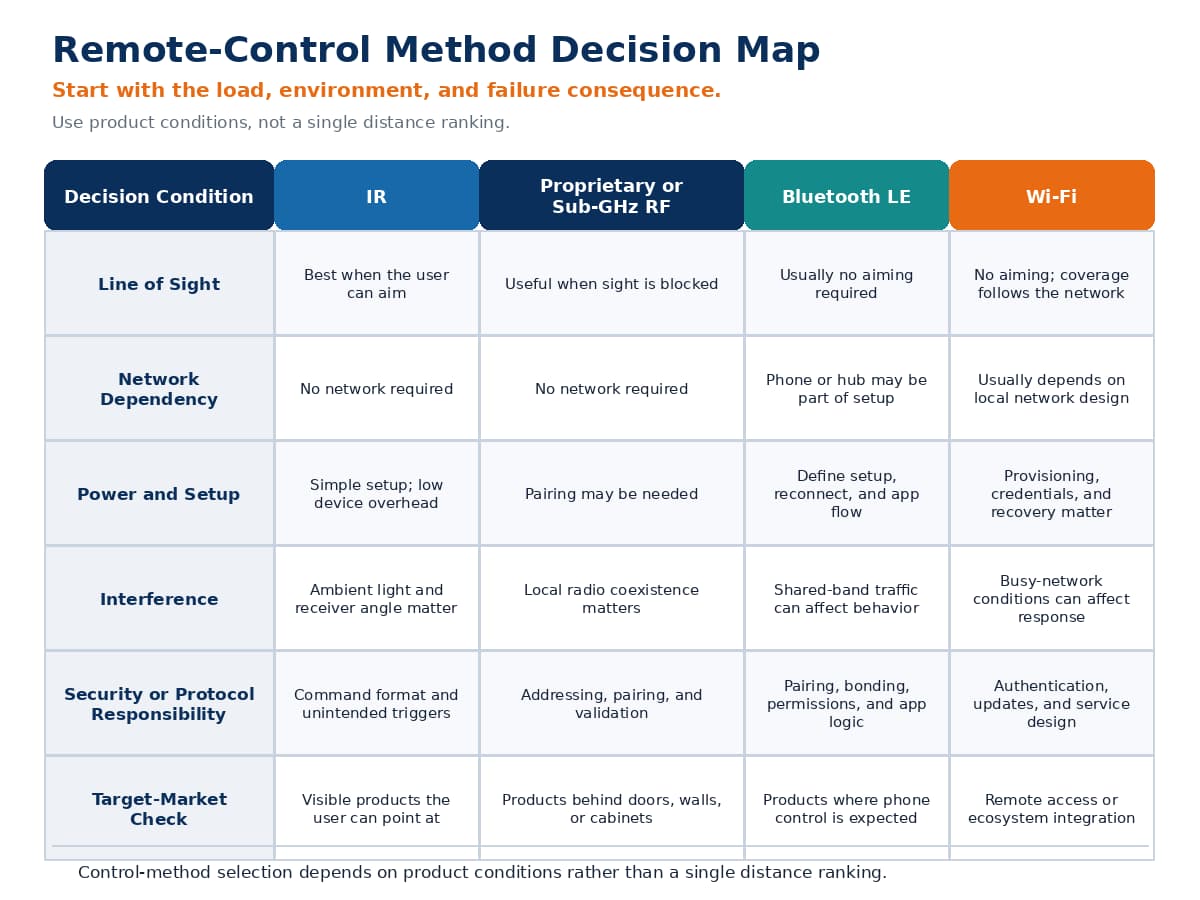
In this comparison, RF refers to proprietary or sub-GHz radio links. Bluetooth LE and Wi-Fi are separated because their protocols, provisioning, network behavior, and product-security requirements differ.
IR suits directional applications, but receivers have different characteristics depending on the manufacturer. Vishay’s IR receiver modules have different characteristics related to carrier frequency, directivity, sensitivity, supply conditions, and disturbance behavior.
Proprietary RF can avoid direct line-of-sight restrictions; however, there is no single solution for proprietary RF. All aspects, including band, modulation, protocol, filtering, antennas, coexistence, and regional restrictions, can interact. For European short-range radio products within its applicable scope, ETSI EN 300 220-2 V3.3.1 may form part of the radio-spectrum assessment. Applicability ultimately depends on the specific operating band, equipment category, transmission characteristics, and intended market; therefore, the standard does not define a universal frequency.
Bluetooth LE supports standardized discovery and the integration of mobile devices or gateways with other devices. The Bluetooth SIG’s documentation, Understanding Bluetooth Range, details the factors affecting reliable range, including the PHY, receiver sensitivity, transmission power, antenna gain, and path loss. The best-case distance indicated for a Bluetooth LE module is not a guarantee of the range of the final device.
Wi-Fi products can form part of an established IP network and provide value where such a network already exists. They also introduce provisioning, credential protection, reconnection, firmware updates, cloud or internet loss, and local fallback decisions. NIST IR 8259 Rev. 1 treats cybersecurity as a product-level responsibility that includes manufacturer activities and the information customers need regarding cybersecurity activities for IoT products (Foundational Cybersecurity Activities for IoT Product Manufacturers). Cybersecurity requirements should include authorization, command expiry, update recovery, and the preservation of essential local control when management services are unavailable. Device cybersecurity requirements should build on the manufacturer’s obligations and be linked to the manufacturer’s software responsibilities related to product provisioning.
No universal remote-control frequency exists, as the answer depends on the technology, physical components, geographic regulations, coexistence, antenna implementation, and operating constraints. The range and latency of a remote-control system should only be compared under a specific set of stated conditions: how it is oriented within the room, whether the location has obstacles such as walls or furniture between the remote-control device and the signal source, whether it is enclosed in a box or other container, what voltage is supplied to the remote-control device, whether other devices create interference, how often data packets are produced, and what failure rate is acceptable.
The Driver Stage Between Logic and the Load
An MCU pin or receiver pin expresses a control decision, while the driver supplies the required electrical interface. The topology of the driver must be suitable for the voltage, current, startup characteristics, inductance, isolation, thermal limitations, and consequences of driver failure. A logic-high output merely indicates that a control decision has taken place, while the driver must still provide the voltage, current, protection, and switching characteristics required by the physical load connected to it. a low-side MOSFET may suit one-direction DC switching. An H-bridge may be required for directional switching and braking in motor control, whereas a relay or isolated interface may be more appropriate when galvanic isolation or specific contact behavior is required.
Inductors release stored energy after the switch has been turned off. Motors may draw additional current during startup or stall conditions. TI provides an example with the ULN2003A low-side Darlington array, which has common-cathode clamp diodes for use with inductive loads such as motors (see the ULN2003A Darlington Transistor Array datasheet). However, using this part does not guarantee that it will be suitable; its rating, voltage drop, heat generation, switching speed, logic interface, and low-side topology must all be matched to the specific application.
Return paths, protection paths, connector ratings, thermal management, and the separation of noisy currents from sensitive reception circuitry must all be considered. Products used in hazardous-voltage or high-current applications require project-specific safety design.
What Should Happen When the Signal Is Invalid or Lost?
Validity does not determine output behavior. Detection or partial decoding does not authorize an output transition. Once accepted, an instruction may result in momentary, toggled, latched, or timed output behavior. A simple diagnostic model establishes four conditions: energy or carrier detection, frame reception, address or integrity validation, and output authorization. Any corrupted frame, incorrect address, or unknown command must be rejected rather than accepted as a new command. Continued signal loss or stale data should invoke the device’s defined signal-loss management policy, which may hold, clear, or change the output after a timeout period. Simple addressing can help reduce the chance of accidental activation of unintended devices, but it does not provide complete protection against unauthorized use.
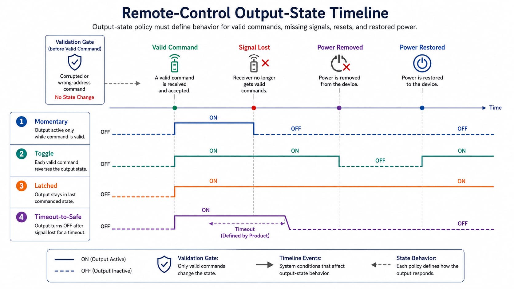
Vishay provides IR guidance on rejecting corrupted messages. One specific example is the HT12D, which checks the addresses of received command frames before indicating that a valid transmission has occurred (see the HT12D/HT12F 2^12 Series of Decoders). Outputs may remain latched until new, acceptable data has been received. This distinction separates data validity from output persistence; it does not establish connected-device security.
Light fixtures may be acceptable with a remembered state, while moving machinery may not. After electric service is restored, one valve may require a defined position, while another actuator may have to wait until instructed again.
Examples of fault scenarios to test include incorrect addresses, corrupted frames, repeated frames, delayed or stale frames, external interference, receiver resets, transmitter malfunction or loss, power cycling, and service restoration. Each test should be conducted in a manner that verifies that an acknowledgment received as part of the communication is not mistaken for actual confirmation that a relay contact changed state, a motor turned, or a valve moved to its final position.
Remote-Controlled Circuit Applications
Consumer IR Appliances
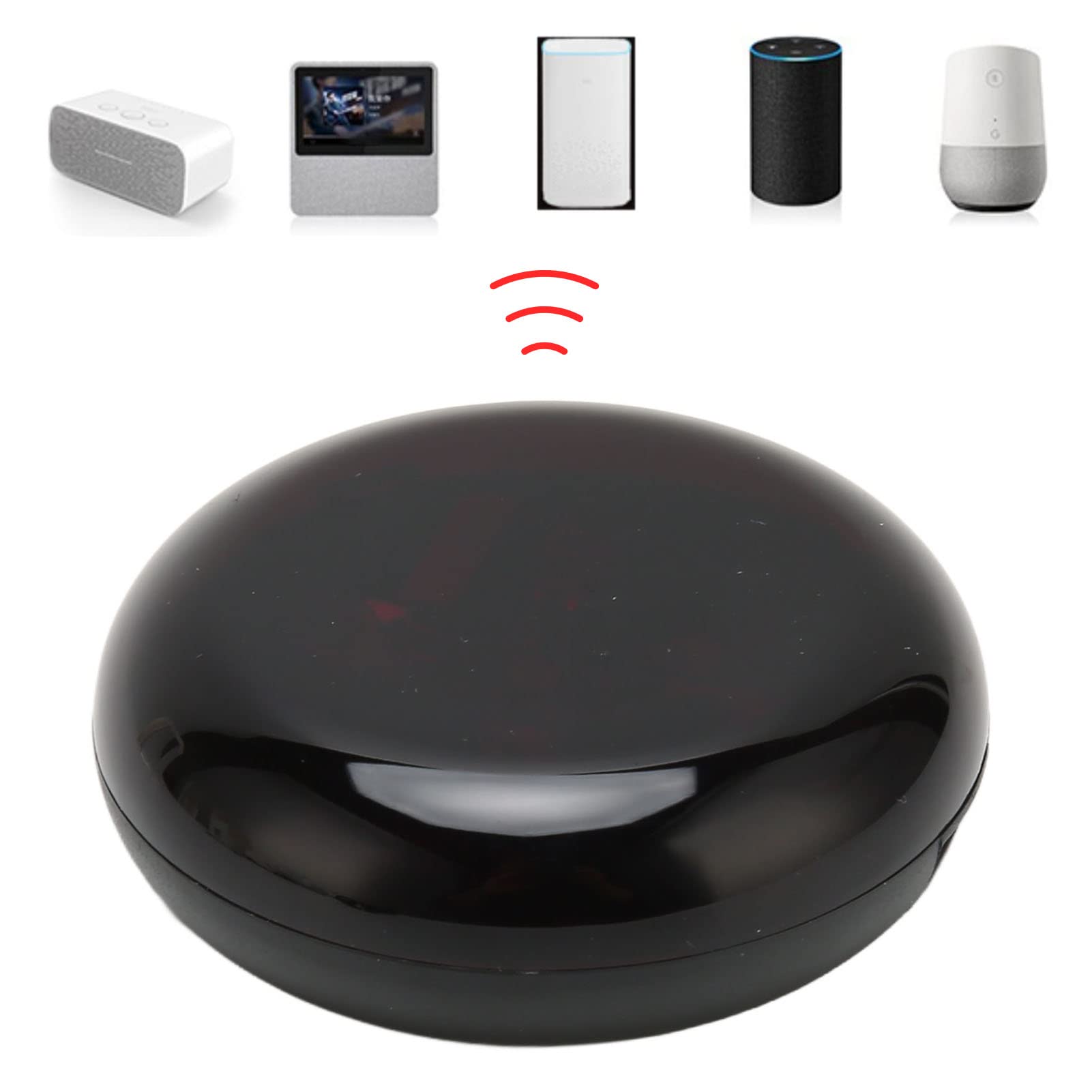
Products such as televisions, fans, and table lamps may be more likely to use IR technology when users can aim a remote at the unit and see the result. For this product type, a compatible carrier is still needed, along with a suitable receiver angle, ambient-light tolerance, repeat handling, and a defined power-up state. An unrelated or corrupted code should not produce an output. A common source of errors occurs when bright ambient light or competing IR sources raise the receiver’s noise level. The unit may operate correctly during a quick indoor demonstration but begin missing valid codes or reacting to unrelated ones under bright sunlight or near another IR remote.
RF Access Actuators
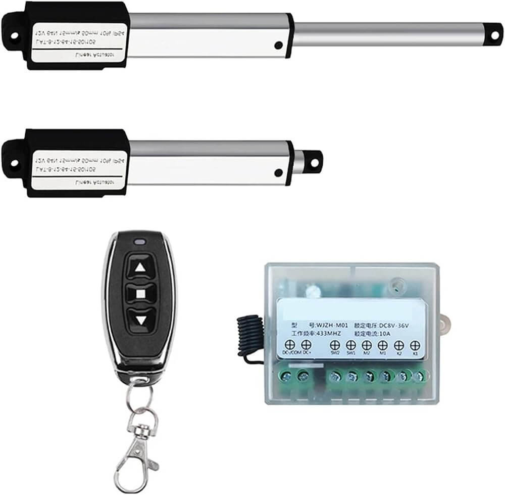
Non-line-of-sight operation for locks, gates, cabinets, and doors removes direct line-of-sight restrictions, but it also introduces a greater need for device addressing, pairing or authorization, interference testing, and position feedback. Energizing a relay should not be the only indication of a successful command; a contact or position sensor may also be needed to verify that the mechanism actually moved.

Bluetooth LE Products
Control via smartphone introduces discovery, pairing, bonding, reconnection behavior, application state, and battery use. The requirements must specify who may control the device, what happens if the smartphone disconnects, whether commands expire, and how the device distinguishes recognition of a valid command from completion of the physical action. A common problem occurs when the smartphone unexpectedly loses its Bluetooth connection during a control session. The application may continue showing the last command as active, and the user may not discover the mismatch until the physical load fails to respond.
Wi-Fi Smart Switches
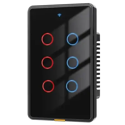
If local IP or cloud integration increases the utility of a networked smart switch, the switch must define provisioning, credential storage, local operation during internet or cloud loss, update recovery, startup state, and whether a returned status represents the software command, relay output, or measured load condition. A typical problem occurs when the application shows the last reported relay state after the cloud connection is lost. The user then sends a toggle command that never reaches the device, and the actual load condition silently diverges from the application until the cloud connection is restored and the two are resynchronized.
Remote-Controlled Motors and Robots
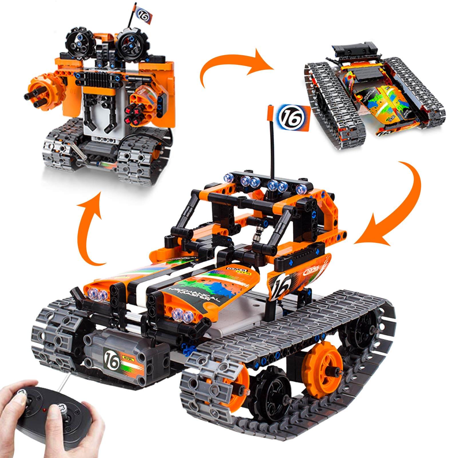
Direction and speed control may require an H-bridge or motor driver instead of a relay. Factors such as startup and stall current, braking versus coasting, PWM noise, battery sag, and link-loss behavior can affect both radio communication and motor movement. A moving device normally requires a defined timeout or stop policy rather than holding the last command indefinitely. One possible failure chain occurs when PWM switching noise couples into the receiver during motor startup. A stationary bench test may indicate satisfactory link performance, while dropped or corrupted packets only appear when the motor is driving the actual load and generating PWM noise.
From Bench Prototype to Reliable PCB
A successful proof-of-concept demonstration using a bench prototype does not prove enclosed range, thermal margin, startup behavior, or immunity to switching noise.
Use three stages to move from architecture to production readiness:
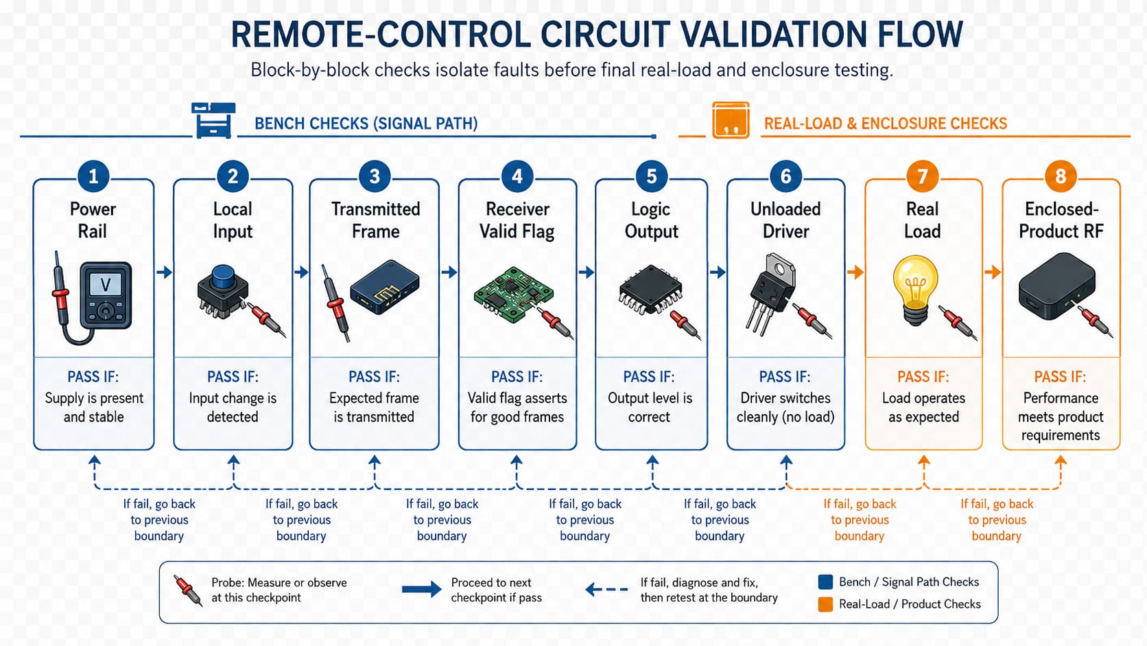
- Define the architecture: Specify the load, communication link, state logic, driver, protection, feedback, and required responses to invalid commands, signal loss, startup, and power restoration.
- Verify each function: Confirm command generation, reception, validation, state transitions, driver operation, and actual load operation under supply, startup, stall, and thermal conditions.
- Validate the finished product: Repeat communication, failure-state, load-feedback, interference, and power-cycle tests using the final PCB, actual load, and intended antenna position.
PCB implementation influences both radio performance and output behavior. Decoupling components located near the power supply pins stabilize the local power rail voltage levels. If the RF return path is interrupted or the matching network is located too far from the antenna, the RF transmission line may not be properly matched to the antenna, which can adversely affect how the antenna radiates energy. The proximity of copper, cables, and enclosure materials can also affect how the RF signal radiates into the surrounding environment. High-current load switching can introduce substantial noise into the receiver power supply or digital logic supply.
The Texas Instruments CC2650 Remote Control Design Guide recommends maintaining a continuous ground path for the RF signal, placing matching components near the antenna, and decoupling power supplies as close to the RF receiver supply pins as possible. The Espressif PCB Layout Design Guidelines specify antenna clearance plus throughput and range testing of the PCB design in the final product enclosure. These antenna layout rules should be validated in the final product enclosure and not considered complete at the schematic or bench-test stage.
Verification of the RF control system should include accepted and rejected messages, specified output modes, acknowledgment of received commands, actual-load feedback if provided, startup, repeated operation, power interruption, supply extremes, switching noise, worst-case orientation, and enclosed communication. Pass criteria for communication and performance should define communication performance, required output timing, acceptable current and temperature limits, and specified safe-state transitions of the RF control system design. A predefined functional testing plan should connect each requirement to an observable result and retained record.
Conclusion
The final circuit design must validate all commands, apply a defined command-state policy, control the actual loads within their electrical and thermal limits, and operate predictably during events such as invalid data, signal loss, resets, and power restoration.
After the architecture and validation requirements are defined, PCB design services can review the PCB design, DFM constraints, and manufacturing preparation for the specific product. Provide the controlled equipment, chosen communication link, target market, enclosure, required failure responses, and available design files.
References & Sources
- RF Smart Remote Control – Texas Instruments
- Sub-1 GHz Wireless Motor Remote Control Reference Design – Texas Instruments
- Data Formats for IR Remote Control – Vishay Intertechnology
- IR Receiver Modules – Vishay Intertechnology
- ETSI EN 300 220-2 V3.3.1 – ETSI
- Understanding Bluetooth Range – Bluetooth SIG
- Foundational Cybersecurity Activities for IoT Product Manufacturers – National Institute of Standards and Technology
- ULN2003A Darlington Transistor Array – Texas Instruments
- HT12D/HT12F 2^12 Series of Decoders – Holtek Semiconductor
- CC2650 Remote Control Design Guide – Texas Instruments
- PCB Layout Design Guidelines – Espressif Systems