Upload BOM & Gerber

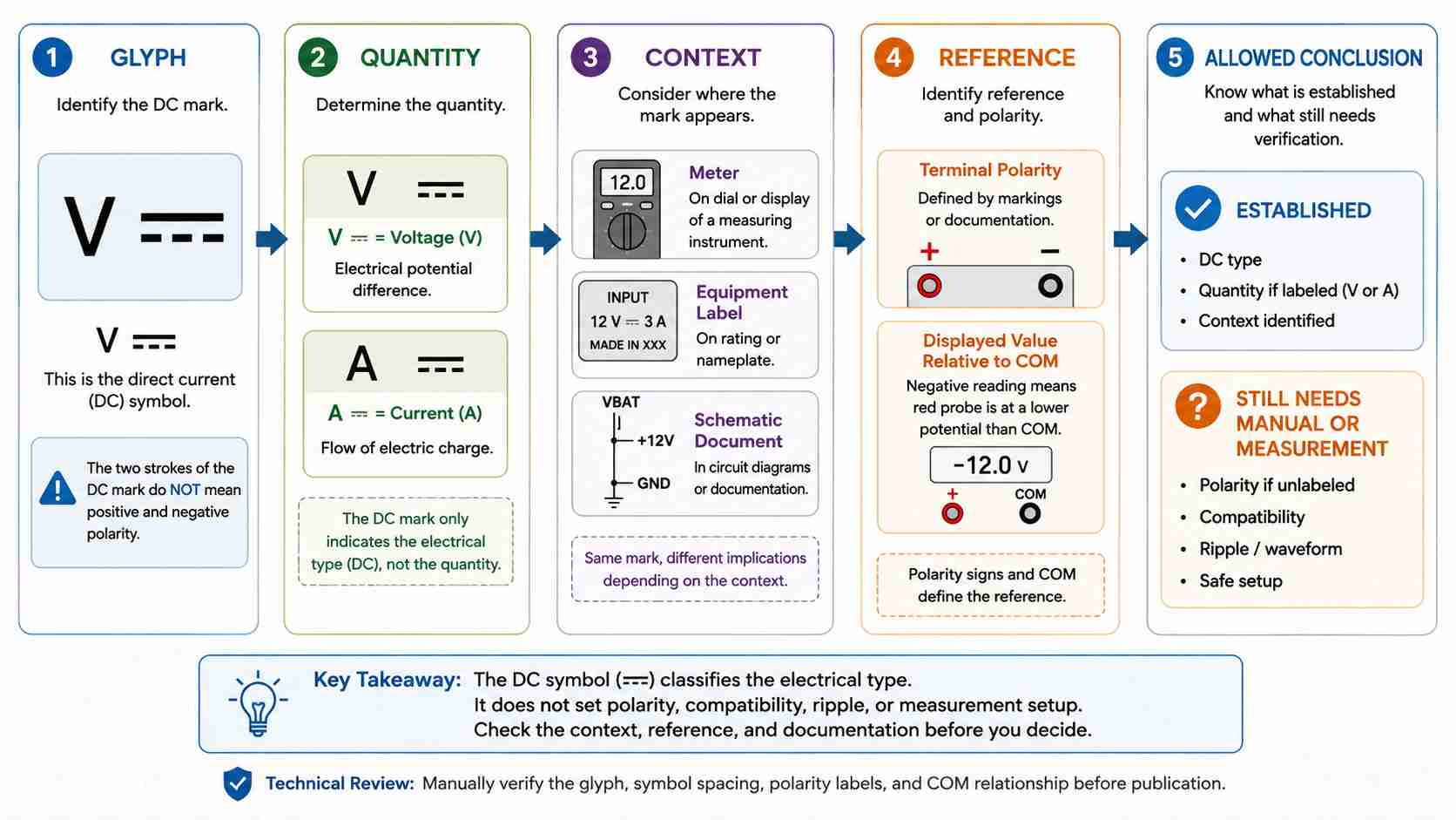
The direct current voltage symbol is written as V with the DC symbol (⎓), where V represents voltage and the DC symbol represents direct current. The two strokes of the DC symbol or the negative sign on the display do not automatically mean that the equipment terminals have a designated positive or negative polarity. The reference points, ratings, and exact equipment manual must be checked to ensure that the user takes the appropriate action to connect the equipment correctly.
Contents
show
What Is the Symbol for Direct Current Voltage?
Direct current voltage is identified as V (for voltage) with the DC symbol (⎓); a common way of writing this symbol is represented as V⎓, with the DC symbol (⎓) either above, below, or adjacent to the letter V. The DC symbol is described by item number 5031 in IEC 60417; the Unicode character for the DC symbol is U+2393, Direct Current Symbol Form Two.
The DC voltage symbol provides two pieces of information:
- V = Voltage.
- ⎓ = DC.
- V⎓ = A common symbol that signals a DC voltage function or reading.
These symbols are addressed by two separate authorities. The name and item number for graphical symbols are published by the IEC/ISO; for text characters, the names are published by Unicode.
Because different manufacturers design instruments differently, a meter may use the DC symbol before or after the V, label it as VDC or DCV, or label its millivolt range as mV⎓. Some manufacturers may use a single selector position to control both AC and DC or may require the use of an additional button to switch between AC and DC modes. Each manufacturer’s convention for the DC voltage symbol represents its specific instrument design, but these presentations do not represent different electrical quantities. For example, the Fluke multimeter dial, button, jack, and display overview uses a composite illustration derived from several models. Always consult your specific model’s manual to confirm its graphic and selection method.
For information on resistance, continuity testing, diode testing, capacitance testing, or any other related markings on a multimeter, please refer to the full guide to multimeter symbols.
What Do V, ⎓, and the Minus Sign Each Mean?
The widespread belief that solid strokes indicate “positive” polarity and broken strokes indicate “negative” polarity has not been supported by the formal documentation. Item 5005 in IEC is identified as “plus” or positive polarity; item 5006 as “minus” or negative polarity; and item 5031 indicates direct current. Each of these items has a different symbol. Polarity can be determined by looking at the terminal markings, using the connection diagram, or measuring relative to a defined reference.
Voltage is defined as the difference between two points. A negative voltage reading on an autopolarity voltmeter does not necessarily indicate a faulty circuit, nor does it imply that COM is automatically Earth. The relationship between the test leads is explained more fully in Fluke’s ABCs of Digital Multimeters.
For the main distinction among negative, 0 V, Earth, chassis, and return, see GND and Voltage Reference.
Read the Mark in Its Actual Context
The voltage of 12 V alone does not indicate whether the voltage source is an AC or DC source. Likewise, there are no indications of terminal polarity, connection type, pin orientation, tolerance level, or wiring condition. Thus, while two voltage sources may have equal voltages (e.g., 12 V), this does not mean that those voltage sources are interchangeable.
Some equipment can accept AC and DC input ranges that are defined separately. However, some equipment may not accept both types of input. Therefore, the MEAN WELL medical power supply FAQs indicate that the ability to accept an AC or DC input depends on several factors, including the specific model of the power supply, the switching condition, and the specified input voltage range.
Unless the specification for the equipment states otherwise, don’t connect a 12 V AC voltage source in place of a 12 V DC voltage source. Different marking standards for equipment and schematic diagrams use different symbols. Markings used on equipment can be found in IEC 60417, while the IEC 60617 symbol database provides graphical symbols for electrotechnical circuit diagrams. The most commonly used schematic rail/net designations include VIN, VBAT, VCC, VDD, +5V, +3V3, and GND. These are rail/net designations in a schematic and should not be confused with the IEC 60417 symbol for DC equipment. Specific notations for batteries, sources, and rails should appear in the equipment documentation or drawing legend.
How Is DC Voltage Different from AC Voltage?
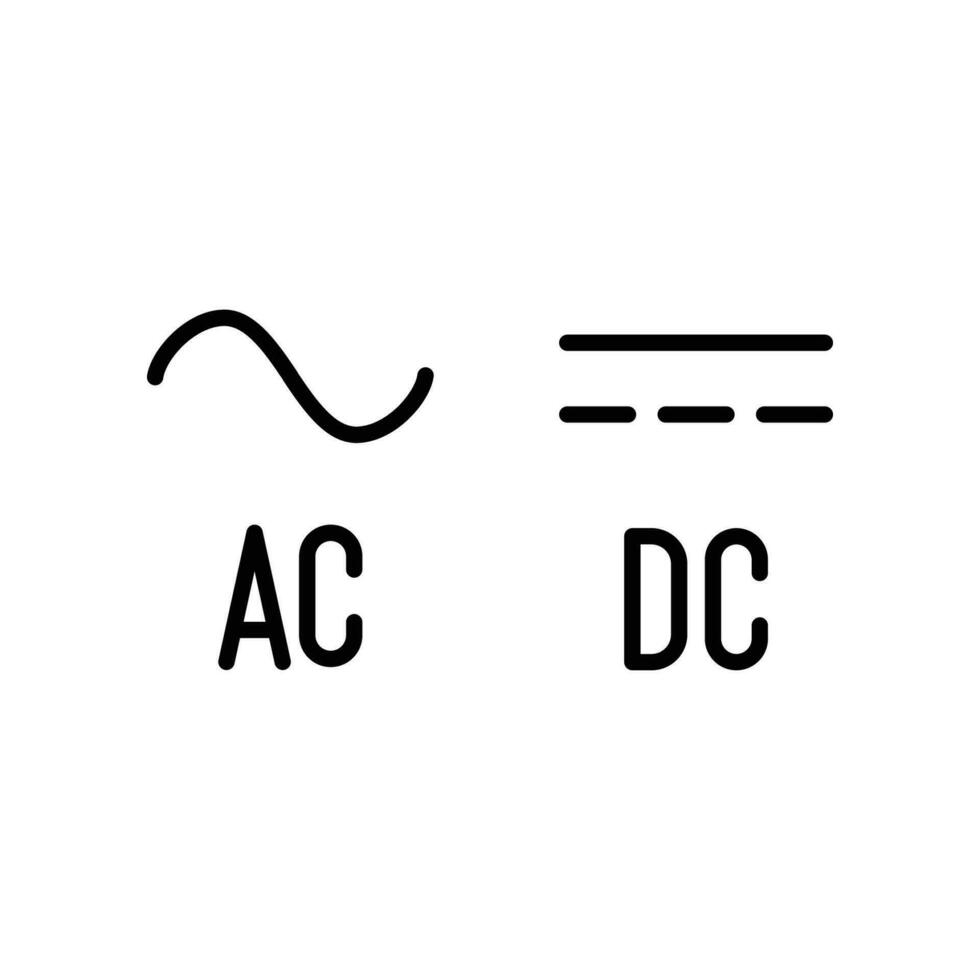
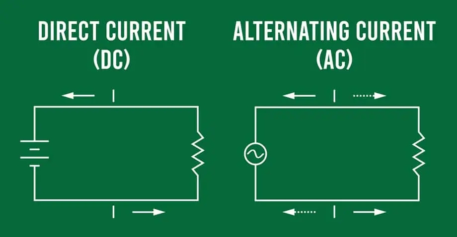
The electrical-type markings distinguish DC and AC. Item 5031 in the IEC equipment-symbol list represents “Direct current,” while item 5032 represents “Alternating current,” and item 5033 represents “Both direct and alternating current.” The adjacent letter still determines whether the control or display concerns volts, millivolts, amperes, or another quantity.
(⎓) denotes DC. However, the quantity, range, terminals, reference, and actual waveform still need to be checked by the user.
(~) denotes AC. However, the frequency limits, range, terminal selection, and equipment ratings are not indicated. A general-purpose meter calibrated for standard 50/60 Hz mains may produce an inaccurate reading of a 400 Hz avionics or ground-support AC supply. Therefore, the symbol indicates the electrical type but does not indicate the meter’s measurement bandwidth or accuracy at 400 Hz.
A combined AC/DC mark indicates that both types of electrical current can be used in the stated equipment context. The specific function and the way in which each type is measured are model-specific.
Selecting the voltage mode (DC) tells the meter which type of measurement to select for the input. However, this does not guarantee that the input signal will be purely DC, nor does it guarantee that the selected range will be safe or that the red lead will be placed in the voltage input. Refer to the user manual for information regarding the instrument.
Selecting the AC mode does not convert a DC signal into an AC signal. It only changes the manner in which the meter measures the signal. The displayed results can differ based on coupling, bandwidth, waveform, range, and model.
Can DC Voltage Include Ripple?
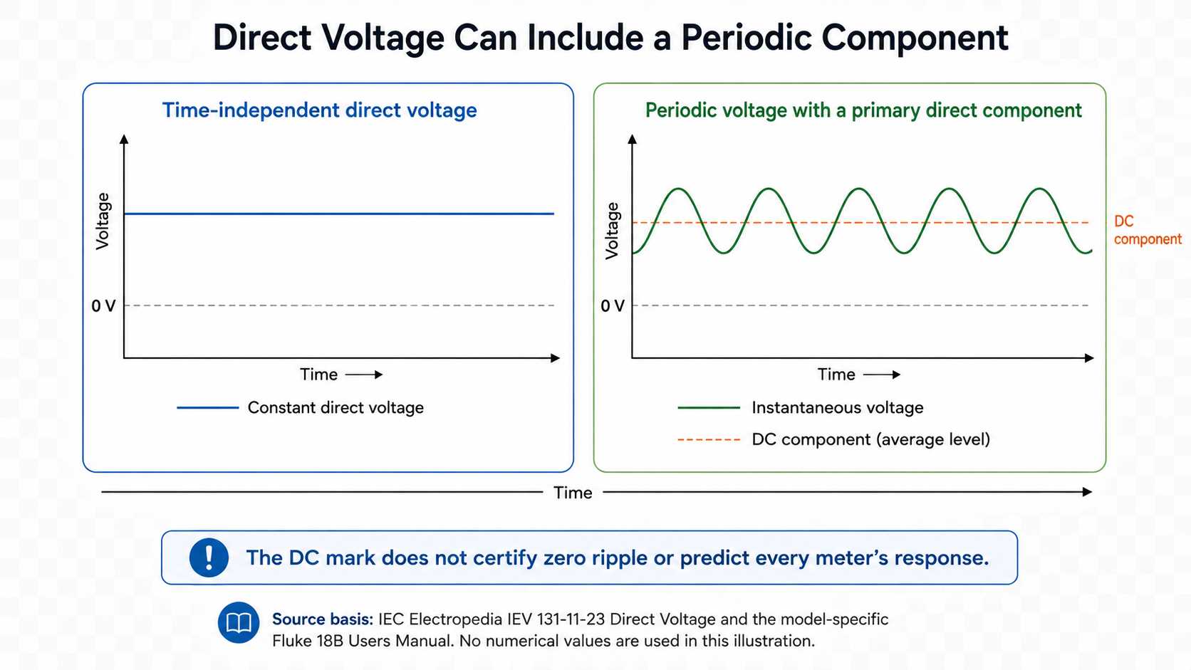
Yes. Direct voltage may be time-independent, but the IEC definition also includes a periodic voltage whose direct component is of primary importance. Therefore, the DC mark does not guarantee that the displayed waveform will be a flat trace with no ripple, that it will have low noise levels, or that it will have acceptable power quality. Its use should be treated as a classification term rather than an actual measurement of the waveform.
IEV 131-11-23 defines Direct Voltage. A source may still be a direct-voltage source even when the instantaneous voltage varies around a nonzero level. Both the amplitude and frequency of that variation must still be measured or specified. For instance, a well-filtered linear power supply might carry only a few tens of millivolts of 100/120 Hz ripple on a 12 V DC output, while a poorly filtered switched power supply on the same nominal 12 V can carry several hundred millivolts of ripple. While both types of power supplies meet the definition of direct voltage, they are not equally suitable for a load sensitive to noise.
Each meter responds differently to mixed-component inputs. An example is provided by the Fluke 18B Users Manual; it gives a defined procedure for testing voltage containing AC or AC plus DC components. This shows that mixed components affect the measurement strategy for that instrument. Therefore, the procedure is not universally applicable to all DMMs.
If the input signal requires measurements of ripple, noise, or transient behavior, the user cannot rely solely on the symbol to determine whether these conditions exist. Therefore, the user must rely on the source specifications and the DMM specifications for supported functions, ranges, and bandwidth. Proper measurement may require an oscilloscope or another approved test method, depending on the signal and energy level.
How to Measure DC Voltage with a Multimeter
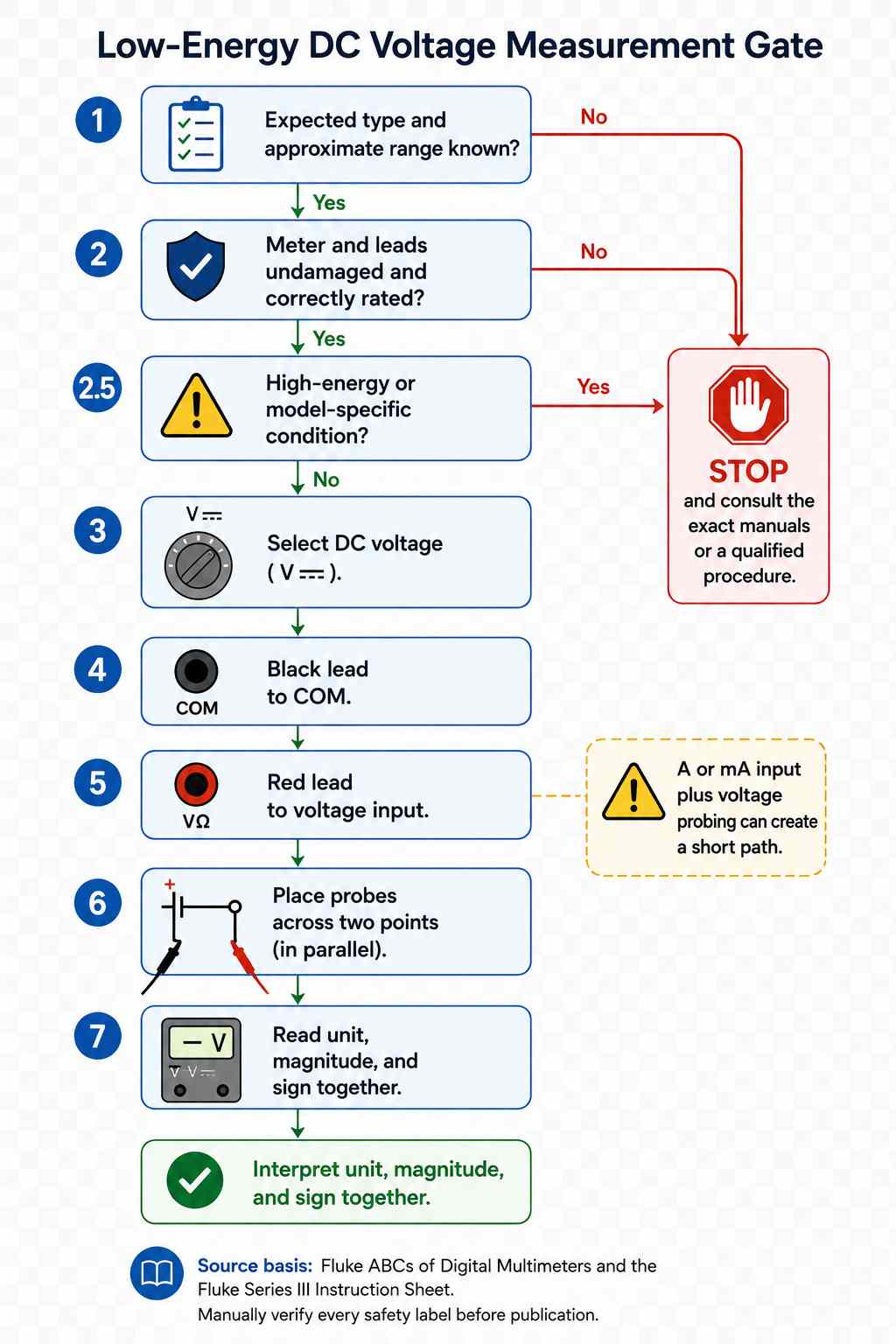
Once V⎓ is found, check the measurement configuration before accepting the reading. Check the function, input, approximate range, parallel connection, the condition of the meter and leads, and the rating of the equipment. To determine the displayed reading, use the COM input and the voltage input, then interpret the unit, prefix, magnitude, and sign together. If you are unsure of the energy level or the applicable ratings, do not proceed.
- Make sure to confirm the expected type of reading and approximate range. If using an auto-ranging meter, selecting V⎓ may suffice for range selection. If you are using a manual-ranging meter, select a range above the expected voltage per the model manual and based on documentation for the target device, not the symbol alone.
- Ensure that the meter and leads are not damaged and that their ratings are clear. If either is damaged or has an unclear rating, stop.
- Select DC voltage and connect the black lead to COM and the red lead to the appropriate voltage input.
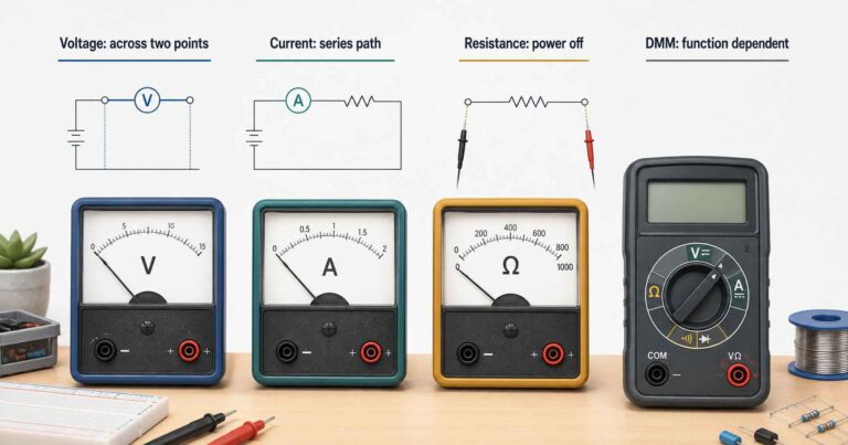
- Connect the meter across two points, not in line or in series.
- Read the entire display and understand the unit, any prefix, the magnitude, and the sign. If a reading displays a minus sign, then that represents the red lead as negative relative to COM.
- Do not proceed if you do not know the energy level, do not understand what ratings apply, the equipment is classified as high energy, or if the function is specific to a certain model. If you do not have exact manuals or qualified procedures, do not proceed.
While measuring current and voltage on a circuit, the methods for current measurement and voltage measurement differ greatly. When measuring current with leads, the meter is inserted in series with the circuit. If the red lead is left in the A or mA input and the probes are placed across a voltage source, this can form a short path through the current input. You must return the red lead to the voltage input before performing a voltage check.
The Fluke application note supports the COM, voltage-input, and parallel-connection sequence for low-energy measurements. The Series III instruction sheet for a particular model also specifies the importance of putting the leads in the correct position, properly using the switches, and complying with the meter ratings. The numerical limits identified for that Series III meter should not be applied to another meter.
Conclusion
The DC voltage mark is a classifier, not a complete measurement instruction, and you can decode the mark using five questions: Which glyph is identified? What quantity is identified? What is the context of the glyph? What is the reference? What will the ratings and documentation allow you to do?
If these questions are answered correctly, they will help to avoid three typical mistakes: assuming that you read polarity based on the strokes of the glyph, concluding that 12 V indicates full compatibility with the expected product, and concluding that a DC-marked product guarantees zero ripple voltage.
References & Sources
- IEC/ISO Graphical Symbols for Use on Equipment Preview – International Electrotechnical Commission
- Control Pictures Names List – Unicode Consortium
- Multimeter Symbols, Buttons, Dials, and Display – Fluke
- ABCs of Digital Multimeters – Fluke
- Medical Power Supply FAQs – MEAN WELL
- IEC 60617: Graphical Symbols for Diagrams – International Electrotechnical Commission
- IEV 131-11-23: Direct Voltage – International Electrotechnical Commission
- 18B Users Manual – Fluke
- Series III Instruction Sheet – Fluke