Upload BOM & Gerber

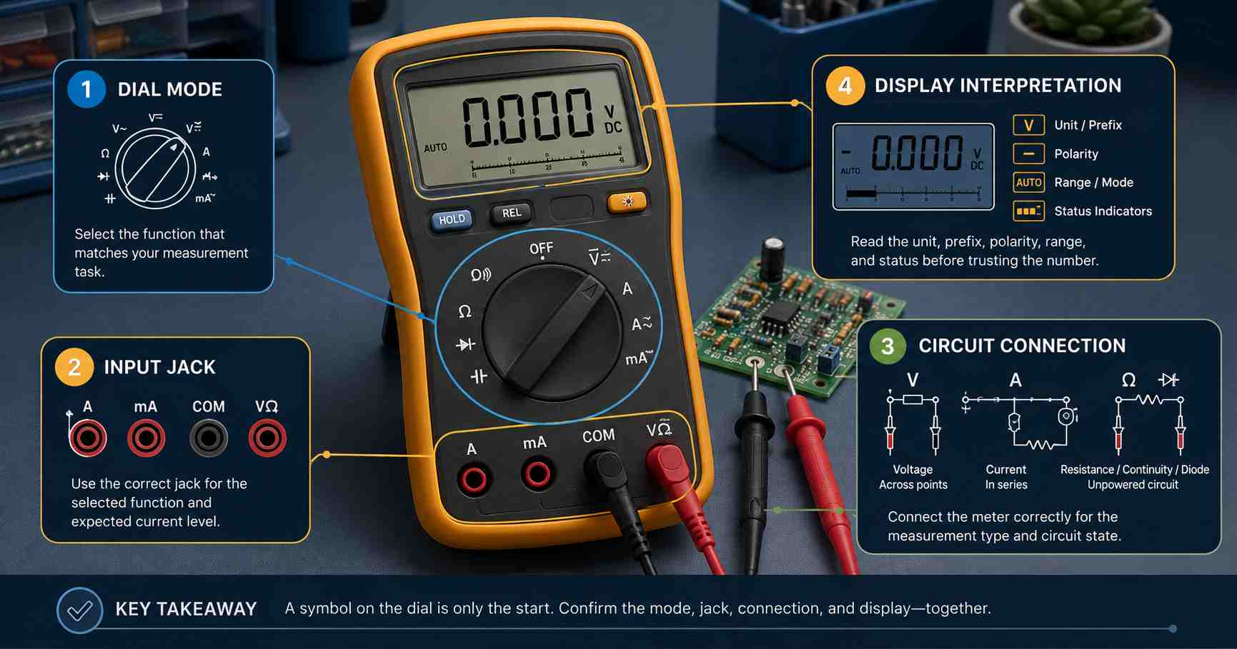
It is necessary to keep in mind the dial mode, input jack, state of the circuit, and display information. Continuity, resistance, and diode modes must not be confused. OL means something different depending on the mode, while shared positions and thresholds depend on the particular multimeter.
An obvious symbol may still not provide a useful reading. The selected input jack may be incorrect, an additional function may be active, or the circuit may need to be unpowered. Even the display may change the meaning because of its sign, prefix, or symbol showing the range.
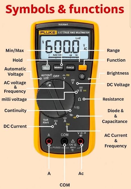
Fluke separates the front panel into the dial, controls, input connectors, and display. It even stresses the fact that its example dial is a mixture of functions taken from different models. Therefore, one should learn the measurement logic and check the symbols on the front panel in the manual.
Contents
show
What Do Multimeter Symbols Tell You?
Multimeter symbols indicate a measurement function, a displayed quantity, an operating mode, or a safety status. There is no single icon set used by all manufacturers. Manufacturers may combine dial positions, colors, and secondary keys differently, so the symbol is the starting point rather than the complete setup decision.
While a rotary function may be defined with the label Ω, it can also identify the unit next to the numerical reading; therefore, m does not create a new measurement but merely scales it. For example, the display of 12.4 mV = 0.0124 V, while 12.4 V is equal to 1000 times the first value. On manually ranged meters, markings such as 200m or 2000m denote a scale and should not be confused with the associated V or A function, which indicates what will be measured.
While icons for Capacitance and Diode Test may resemble the schematic symbols used in circuit diagrams, the function of a multimeter icon is to select a measurement mode instead of identifying a circuit component. Refer to the capacitor schematic symbol reference or LED schematic polarity guide when moving from multimeter setup to circuit documentation.
Read the Meter in Four Layers
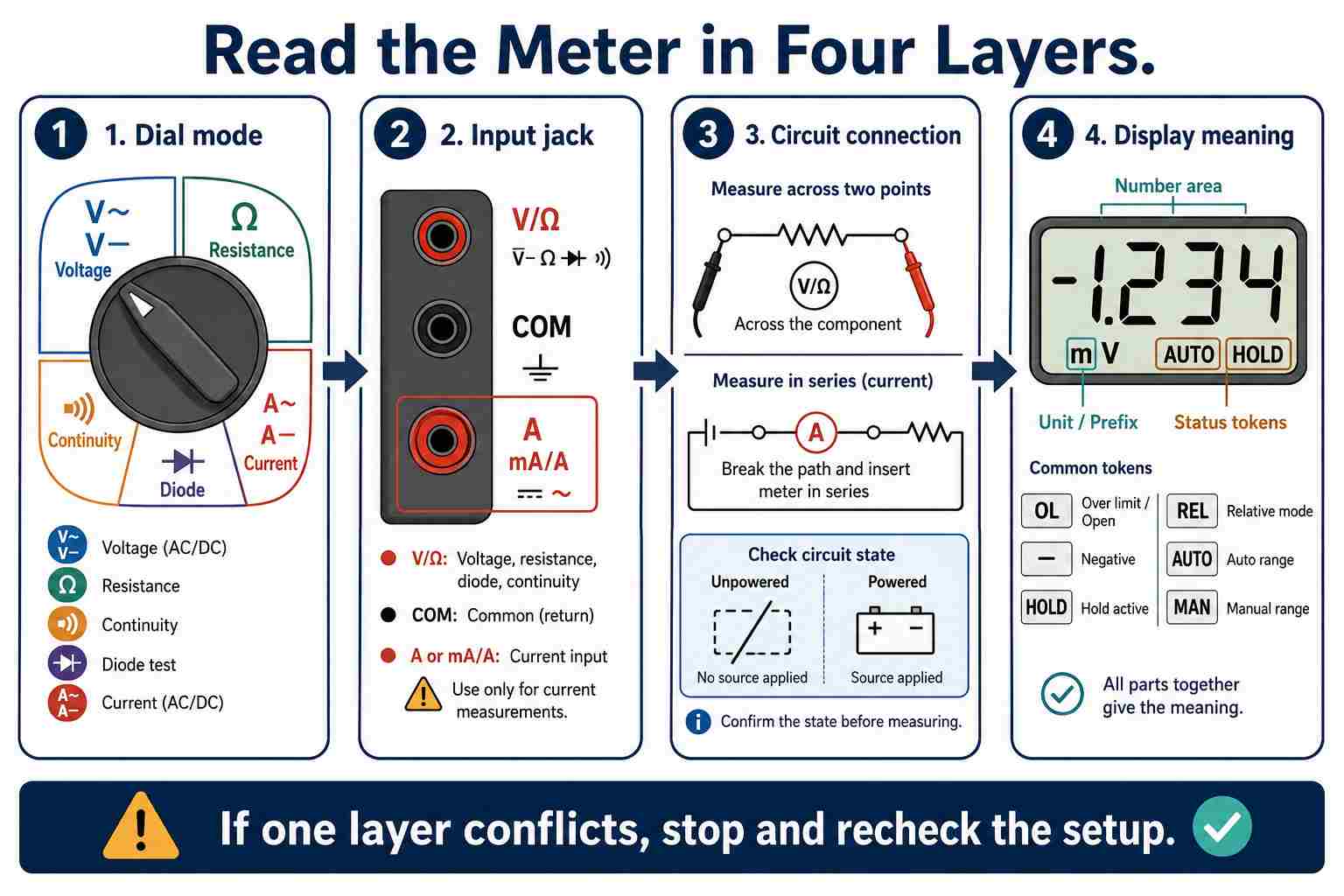
The order of reading a digital multimeter is dial mode selection first, input jack connection second, circuit connection third, and lastly display reading. There are two components to the display: the unit or prefix and the current state.
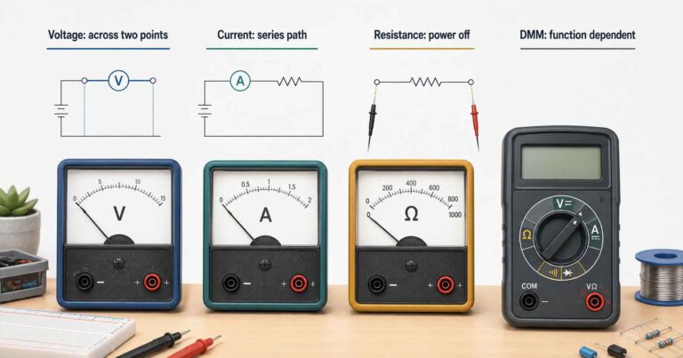
The first layer is the actual task you want to perform, which will define the initial reading mode (voltage, resistance, continuity, diode drop, current, etc.). The second layer is to examine the physical input of the meter (the black lead is usually connected to COM). The third layer is the way the meter is making a connection to the circuit. Voltage readings are taken across two points; resistance, continuity, and diode readings normally require the circuit being tested to be unpowered; current requires that the meter be inserted somewhere in a broken circuit path.
Finally, read everything on the display; for example, a number without any unit or prefix is not a complete reading of the amount measured. This can change depending on factors such as AUTO or MAN, HOLD, REL, a negative sign, or OL. If something doesn't add up correctly after checking all four layers, stop using that reading.
How Do You Match a Measurement Task to the Right Setup?
Before making contact with the probes, match the setup to the measurement.
The Klein MM600 manual directs the user to remove power, open the circuit, connect the meter in series, and then energize the circuit. When connecting a meter configured for current directly across a voltage source, the current input creates a very low-resistance connection between the two leads of the meter.
The order of connecting leads while preparing for a given measurement should also include the correct lead position after the measurement. After taking the current measurement, reconnect the red lead to the V/ohm input to ensure that this is the location of that lead at the next voltage measurement. Checking visually that it has been returned is always better than relying on memory.
Resistance mode works slightly differently from continuity mode or diode mode, in that power has to be disconnected and any stored charge must be considered before resistance readings are taken. In this mode, the meter might measure multiple components in the same circuit, not just the value printed on one component. To ensure accuracy in resistance measurements, the component being tested may need to be isolated from the circuit, and the service manual procedures for isolating components should be followed.
Why Are Continuity, Resistance, and Diode Modes Different?
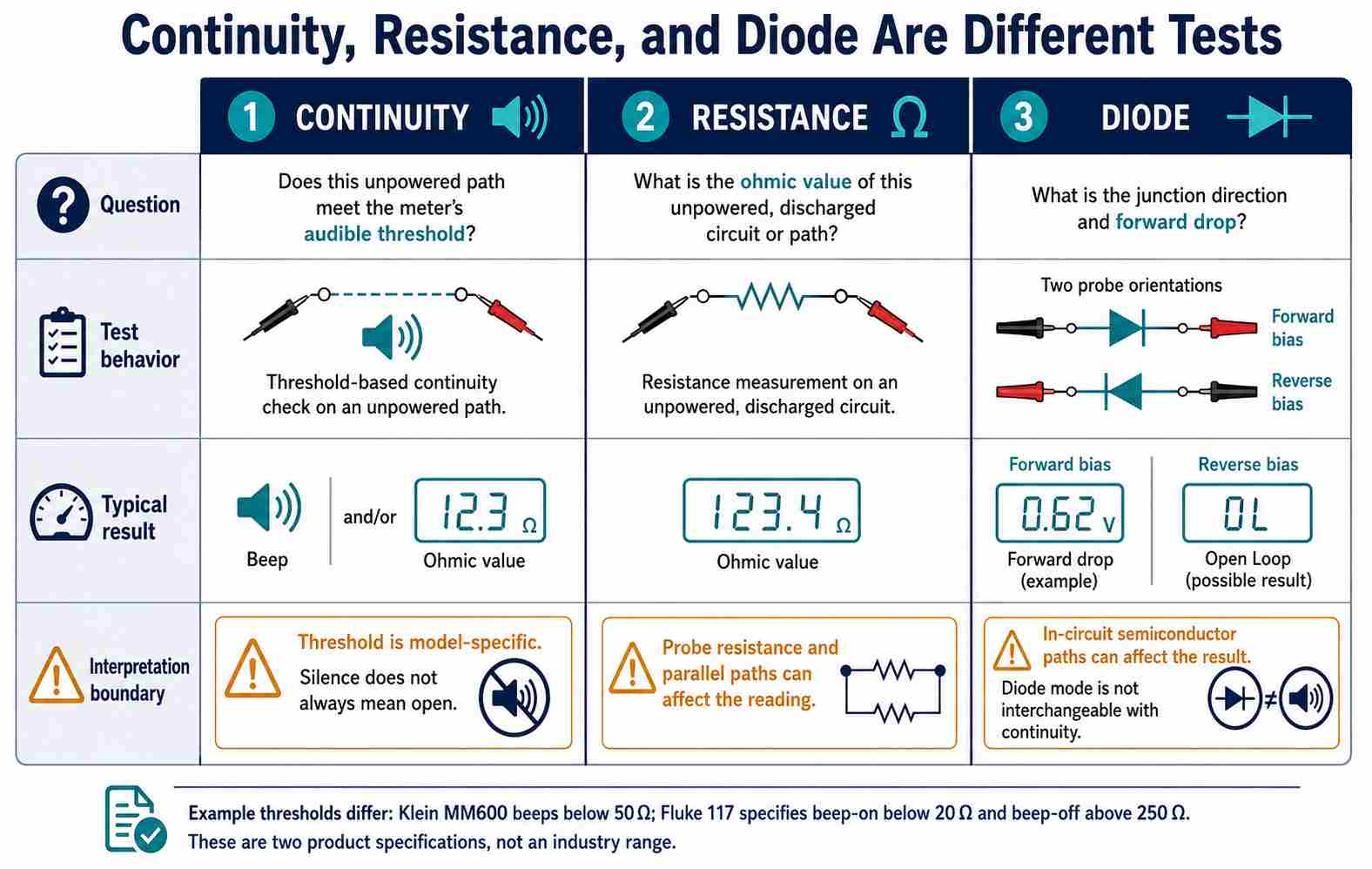
Continuity, resistance, and diode modes have different rules for interpreting the measurement. The continuity test determines whether the measured path is below the specified audible threshold for the meter. Resistance indicates the ohmic value measured for that path. The diode test applies a test signal to determine junction direction and forward voltage; therefore, one measurement cannot be substituted for the other two types.
Each meter has its own test criteria when using continuity mode. The Klein MM600 is set to sound below 50 Ω and has a maximum continuity test current of 0.35 mA. The specifications for the Fluke 117 indicate that it sounds below 20 Ω and does not sound above 250 Ω. This is not an exhaustive listing of an industry range; rather, these are simply two specifications representing those products.
The difference between the beep-on and beep-off thresholds means that silence does not always indicate an open circuit. Other meters may have different settings, such as different thresholds, different latching mechanisms for determining when a path is present across two meter leads, or different response times before producing an audible signal. Because of these variations, refer to the manufacturer's documentation regarding audible continuity indicators.
Resistance presents additional complications, as multiple paths may exist through a circuit. The manufacturer's documentation for Fluke's resistance measurements suggests that the presence of parallel components can result in a reduced in-circuit reading. The resistance of the probes and leads can further contribute to the reading when measuring near zero resistance. To gain the most accurate reading possible, attach the probes to each other and check the baseline reading. If your meter can measure REL, use that setting if the procedure supports it.
The diode mode should not be assessed solely based on whether it beeps or not. When checking a semiconductor junction, check in both directions and compare the readings you receive against published component data and the overall circuit topology; you may find that the presence of an additional semiconductor path across the board could have an effect on your reading.
What Does the Display Mean in the Selected Mode?
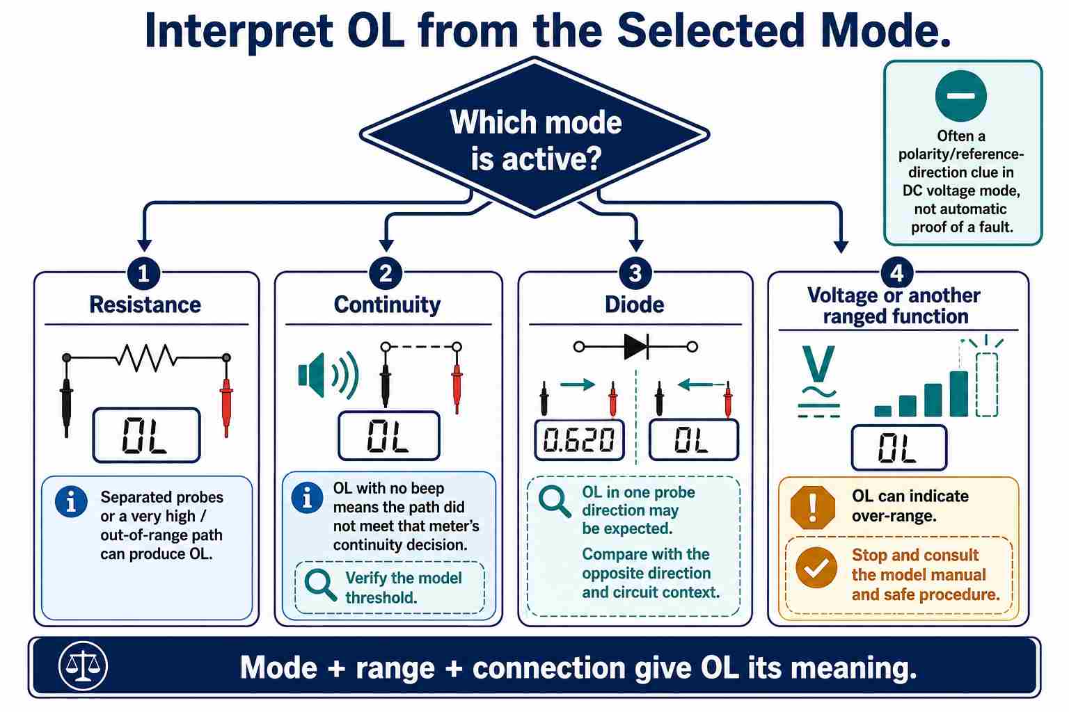
You cannot understand the display indicators without considering the selected mode, range, and type of connection. An OL display may indicate that the resistance between two leads is open or beyond the available range, that a diode is reverse-biased, or that an input is over range. The minus sign displayed can indicate the polarity of the connection; however, that minus sign does not necessarily indicate that the circuit has failed.
In resistance mode, an OL reading with separated probes generally indicates an open path or a value that exceeds the maximum range. When reading in continuity mode, there may be no sound due to an above-threshold value. You may also see an OL condition in one direction of a diode junction and a forward voltage drop when the probe polarity is reversed. This is expected for a semiconductor junction.
The significance of the negative sign on the display varies depending on the context. When measuring DC voltage, a negative sign means the probe reference is opposite to the measured polarity; if the probes are switched while measuring, the same voltage magnitude may be read, but with a positive sign. Refer to the meter manufacturer's manual before attributing that meaning in different modes.
Always record the unit and prefix, not just the digits displayed on the screen.
Model-Specific Symbols and Secondary Functions
Shared dial selections and colored labels are designed to be shortcut keys for one meter interface. The sequence and default selection do not transfer to other brands.
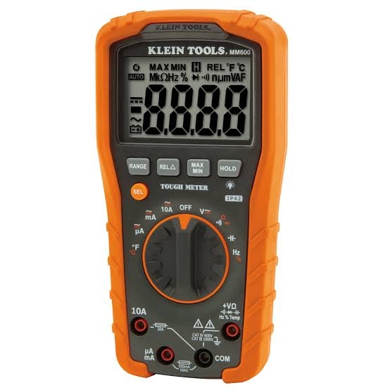
The MM600 is an example. Its SEL button selects several of the shared functions such as AC/DC, resistance/continuity/diode, and frequency/duty cycle, along with temperature units. Someone observing the printed secondary icon but who does not see the active display annunciator can still record the incorrect quantity.
Some meters will have markings that are model-specific:
- LoZ employs a lower input impedance to minimize some types of ghost-voltage effects, and different models implement and rate different ways of achieving this. A common example is an unpowered branch circuit with capacitive coupling that can still run parallel to a powered circuit, showing a few tens of volts of capacitively coupled ghost voltage on high-impedance inputs; by switching to LoZ, that coupling is loaded down, causing the reading to collapse to almost zero volts if the branch is indeed de-energized.
- LPF utilizes low-pass filtering based on a specific metering context; the cutoff and behavior of the filter are model-specific. For instance, a use case would be measuring the output of a VFD; this output produces PWM switching noise, which can cause jumpy or high readings without filtering; the LPF setting attenuates this switching noise and allows the display to settle on the underlying fundamental frequency.
- NCV indicates non-contact voltage detection; it is not a substitute for a complete prove-test-prove or lockout procedure.
- True RMS describes an AC measurement method within specified bandwidth, crest factor, and range conditions and can matter on non-sinusoidal loads where an averaging meter may be inaccurate.
- hFE supports a transistor gain check on some meters, often through a dedicated socket, but it is not a complete transistor characterization.
Before use of any unknown mark or completing a task, determine the exact model number, position of the dial, secondary key required, what the display's numerals represent, what inputs are permitted, and what ratings exist by locating the manual. Just because its visual appearance is similar to other devices does not guarantee it employs identical internal circuitry.
Where Does Safe Bench Diagnosis Stop?
Low-voltage habits established at a workbench are not automatically applicable to mains or high-current applications. Relevant equipment safety standards include IEC 61010-2-033:2023 and IEC 61010-031:2022, as the first describes safety requirements for hand-held multimeters capable of measuring mains voltage, while the second provides information specific to probe assemblies used with the multimeter. Therefore, you should not rely on a rated meter to consider a probe assembly safe if there is any question about the integrity of the probe, since it could lead to severe equipment damage or personal injury. CAT II/CAT III/CAT IV labels, warning marks, fuse information, and double-insulation symbols are safety markings rather than measurement modes, and a symbol legend alone cannot establish suitability for live work.
When performing live measurements, you should stop if any of the following items are unknown:
- Installation category and intended environment for transients
- Rated terminal, range, fuse, and whether the input is in a configuration suited for measurement
- Category of probe, rated voltage, presence of finger guards, and insulation condition of the probe
- The combination of the dial setting with the selected jack and the task you are performing
- Isolation, PPE, access, and qualification standards for that specific equipment
The abbreviation COM does not indicate protective earth. Rather, it refers to the meter's common terminal. The actual reference point of the probe is derived from the circuit and measurement plan. For the distinction among Reference, GND, Chassis, and Protective Earth, use the GND definition and return-path guide instead of guessing from the color of the probe.
From Selected Points to Production Electrical Testing
The handheld DMM is good for verifying local connections on a PCB at the probe points that you selected, but it does not cover the required PCB netlist, nor does it confirm that all of the connections were tested completely.
For reproducibility on the bench, you would maintain a record for each round of testing that includes: the nodes that were checked, which mode and jack were used, which state the circuit was in, the unit that was checked, and the acceptance basis.
When netlist-driven flying-probe or fixture testing is completed, mapping of continuity and isolation of a PCB can be determined across many connections with controlled exclusions and revision-linked results.
The SUGA PCB electrical testing guide covers these production tests.
For whole-board or repeatable lot acceptance claims, a documented test plan should be followed.
Frequently Asked Questions
Q1. Does 0 ohms always mean a short?
No, a low-resistance display of approximately zero ohms could also be a combination of probe and lead resistance, meter resolution, parallel paths, or intended low resistance. To define a fault as a short, remove the power and observe the initial shorted-probe resistance; determine the nodes being compared and compare the results to the board design.
Q2. Can a multimeter locate every dead short on a PCB?
A DMM can detect low resistance between selected probe points, but it may not identify the physical fault on the PCB. To isolate dead shorts, it may be necessary to use one of the following methods or combinations of methods: controlled current limiting, voltage-drop comparisons, thermal measurements, schematic analysis, or component isolation. All of the above methods require dedicated diagnostic procedures and should not be treated as part of an expanded symbol legend.
Conclusion
The symbols indicate the intended function of the test; however, all readings are subject to the active mode, input jack, PCB connection, PCB circuit state, and displayed unit.
References & Sources
- Multimeter Symbols, Buttons, Dials, and Display – Fluke
- MM600 Instruction Manual – Klein Tools
- Fluke 117 Electricians Multimeter Technical Data – Fluke
- How to Measure Resistance with a Digital Multimeter – Fluke
- IEC 61010-2-033:2023 – International Electrotechnical Commission
- IEC 61010-031:2022 – International Electrotechnical Commission