Upload BOM & Gerber

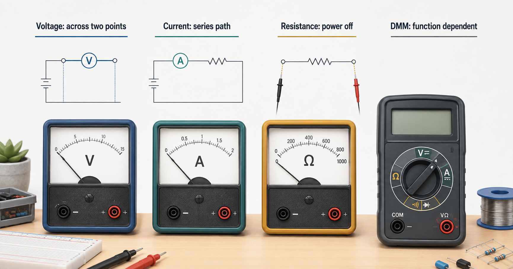
Voltage is the difference in electrical potential between two points, measured in volts; current is the flow of electric charge through a circuit, measured in amperes, and resistance is the opposition to current flow through a conductor, measured in ohms. To measure voltage across two points, use a voltmeter. To measure current flow through a conductor, use an ammeter inserted in series. To measure the resistance of an item, use an ohmmeter on an unpowered, discharged target.
The V, A, and Ω functions of the multimeter only work correctly when the selected function, input jack, range, leads, and rating match the user’s needs and the type of electrical equipment being measured. Changing from V (voltage) to A (current) to Ω (resistance) changes the electrical path through the multimeter. Depending on the type of meter being used (ohmmeter, multimeter, voltmeter or ammeter), the disturbance introduced by the measurement and what the displayed numeric value can establish are different.
- For measuring voltage, only measure across two points. For measuring current through a circuit, only measure in a series configuration (i.e., all current must flow through the ammeter).
- When using resistance mode (ohmmeter), only measure the resistance of an electrical component when the target is unpowered and discharged, isolating the component when parallel paths would change the result.
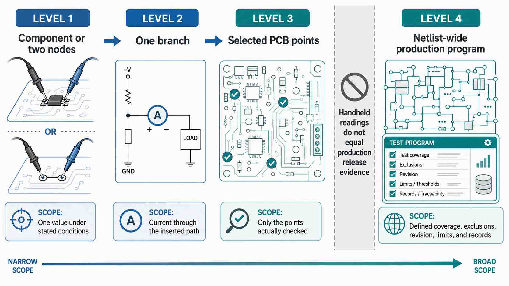
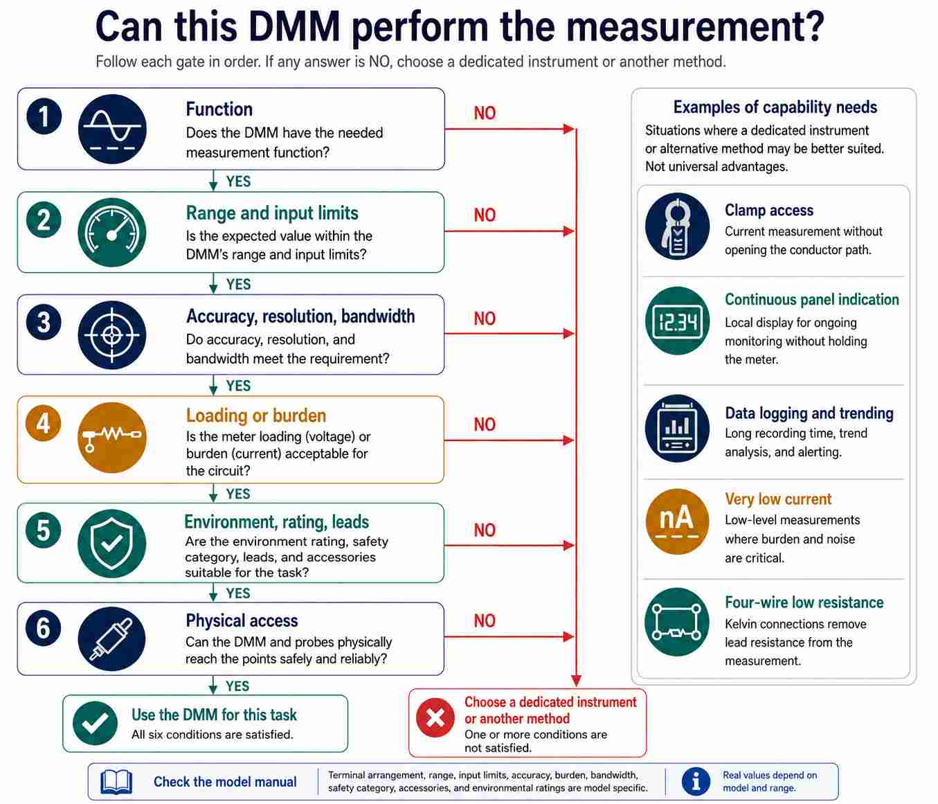
- Do not assume a multimeter will replace a dedicated meter because there are many differences between the two. Always assess the user’s needs by comparing the function of the meter against the limitations (input limits, accuracy, bandwidth, safety, etc.) of each meter.
Contents
show
Ohmmeter, Multimeter, Voltmeter, and Ammeter at a Glance
A multimeter is a configurable instrument that combines several measurement functions in one unit. The name alone does not tell you its ranges, input limits, accuracy, resolution, bandwidth, or safety rating, so the specifications still define what a particular instrument can do (NIST SI Units; Fluke electrical measurement guidance).
In addition to measuring voltage, current, and resistance, many of today’s DMMs can also measure capacitance, frequency, temperature, and duty cycle, and some can record measurements over time or provide continuity and diode-test capabilities. However, there is no single list of available features; for example, Fluke offers different combinations across its various DMM families depending on the model selected.
Both analog and digital describe how an instrument senses or displays the measurement result; however, they do not indicate different electrical quantities. Regardless of whether an instrument is analog or digital, it needs to be connected properly according to the measured quantity.
First, to read current on a DMM, not only must you select the current function and use the correct current input, but you must also connect it in series with the circuit. Simply turning the dial does not adequately prepare the DMM for this.
Second, just because a voltmeter, ammeter, or ohmmeter is designed specifically for these measurements does not necessarily mean it will always provide more accurate results than a DMM.
How Does Each Meter Connect to the Circuit?
One common way to damage a DMM is to set it to resistance mode and then place the probes on a live circuit; doing this can damage the meter’s input protection circuitry. The second problem with taking resistance readings on a powered circuit is that it produces misleading values, since the DMM attempts to apply its internal test stimulus while an external source is also present. Before connecting the DMM, making sure the circuit is in the appropriate state is what makes the displayed value meaningful (OpenStax, Electrical Measuring Instruments).
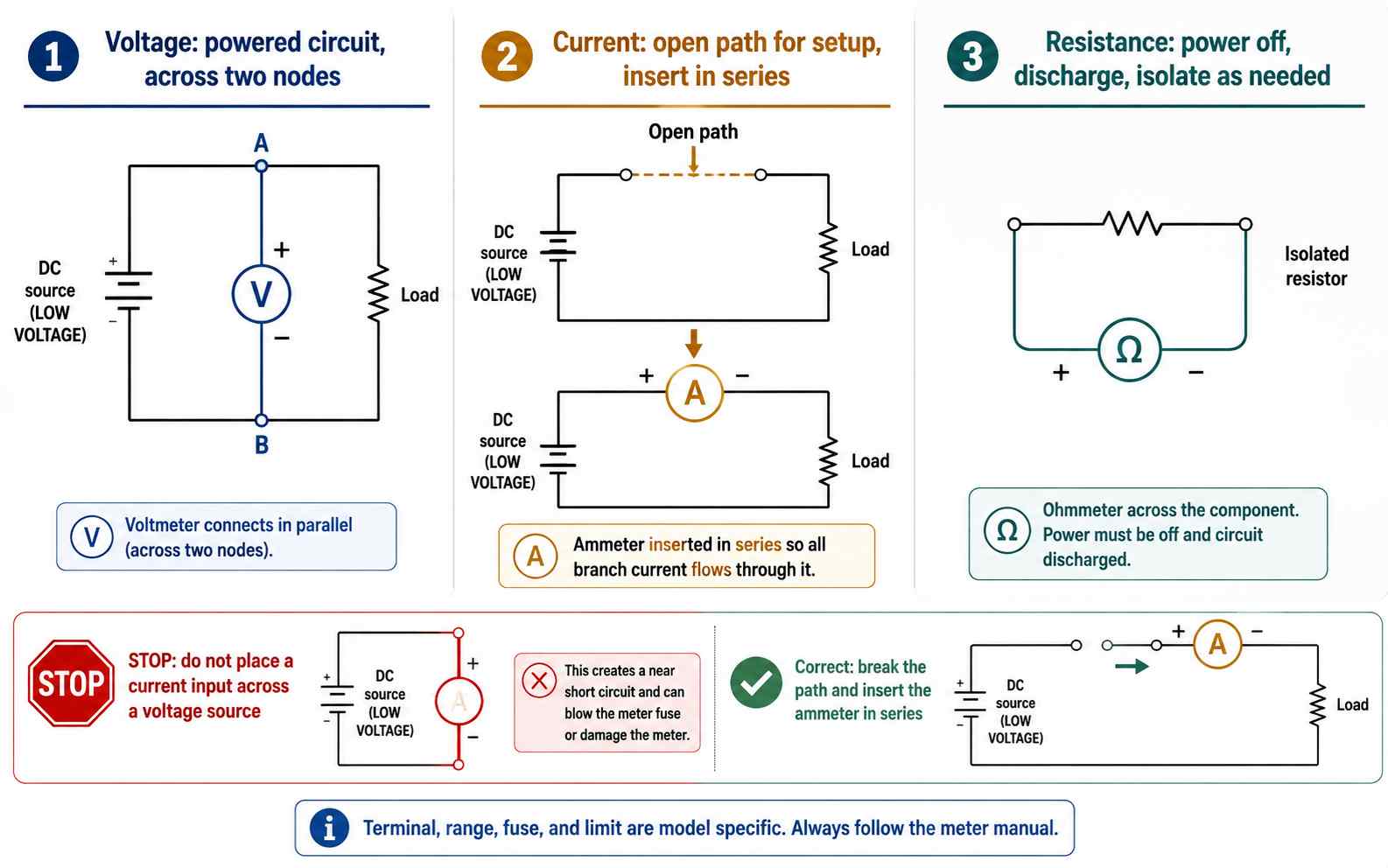
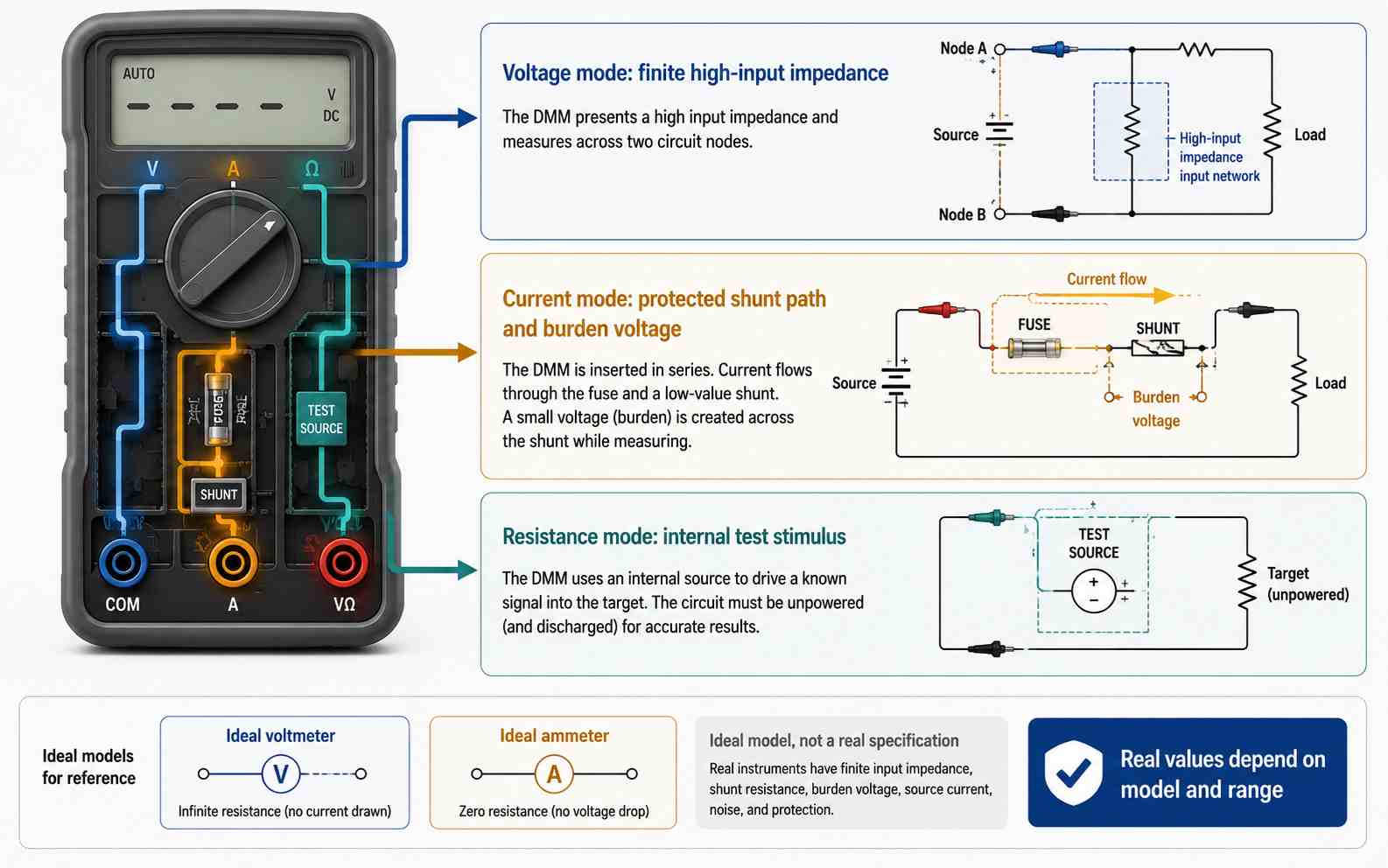
A DVM will typically be connected across two points in the circuit (in parallel) and should have a high input impedance in relation to the impedance of the source circuit to limit current draw from the source. An ammeter, on the other hand, connects into a branch of the circuit by opening the branch and feeding the current through an internal, low-resistance path that is not a zero-ohm wire and creates burden voltage in the circuit.
If you are about to connect the A or mA input of the multimeter directly across a powered load or voltage source, stop and check the circuit topology, terminal, fuse, estimated current, multimeter rating, and the meter manual. Not all multimeters have the same maximum current ratings.
The polarity of the leads should always be considered when making DC voltage readings, as reversing the polarity of the two leads on a DMM will typically change the sign of the readout. The red lead of a DMM will normally be attached to the point you expect to be at a higher potential, and the black lead will be used for the lower-potential or common reference point. If the red and black leads are swapped, the DMM will typically read a negative voltage; however, an analog meter may respond differently, so its polarity and overload instructions should be followed.
Resistance mode will supply its own test stimulus. Disconnect power from the circuit to be tested and allow sufficient time for any connected capacitors to discharge. If other conductive paths exist through the device or surrounding circuit, determine whether they could have a significant effect on the test results. When measuring the resistance of a circuit component with a multimeter, lifting one lead, if possible, will isolate that measurement from the equivalent resistance of the other components in the circuit.
Why Does the Meter Change the Circuit It Measures?
An infinite-resistance voltmeter and a zero-resistance ammeter are ideal models, not real specifications; voltage mode has finite input impedance, current mode has nonzero path resistance, and resistance mode applies an internal test stimulus.
With a Fluke 80 Series V multimeter, voltage loading becomes significant when the source resistance is large compared with the input impedance of the meter being used to take the reading. For most voltage ranges on this particular model, the Fluke 80 Series V multimeter has an approximate input impedance of 10 MΩ. This means that if you measure across a 1 MΩ source impedance, the displayed voltage will be about 9% lower than the true voltage; this effect decreases as the source resistance becomes small compared with the meter’s input impedance, resulting in less than 1% error with respect to the true voltage at a 100 kΩ source and the 10 MΩ input impedance of the Fluke 80 Series V meter.
The Tektronix DMM4020 demonstrates that a rating given as a single value for input impedance cannot necessarily be taken as universal. For example, in normal use with a single display and no other load connected, it specifies 10 GΩ or greater for both the 200 mV and 2 V DC ranges, while the 20 V, 200 V, and 1000 V ranges are specified as 10 MΩ ±1%. This means that a meter that only slightly disturbs a low-impedance power-rail circuit may introduce significant divider error into a high-impedance circuit.
In a similar manner, current measurement reverses the design priority. With respect to the DMM4020, the current shunt on the 20 mA and 200 mA ranges is 1 Ω, while the shunt on the 2 A and 10 A ranges is 0.01 Ω. Tektronix also specifies the burden voltage of the 20 mA range to be less than 0.05 V, the 200 mA range to be less than 0.5 V, the 2 A range to be less than 0.1 V, and the 10 A range to be less than 0.5 V. The burden voltage of the 200 μA and 2 mA ranges has a limiting specification of less than 5 mV. These specifications illustrate that selecting the range changes the amount of disturbance introduced into the circuit as well as the measurement resolution (DMM4020 Datasheet).
Resistance testing introduces a third area of interaction. Resistance is measured by applying a known internal test stimulus and monitoring the response. Semiconductor junctions, alternate conductive paths, and lead or contact resistance can significantly distort in-circuit or very-low-resistance measurements. Using the four-wire method when testing very low resistance can reduce lead resistance error; testing at very high resistance or very low signal levels may necessitate low-level techniques to account for thermal EMF effects, input current, noise, and leakage current.
Can a Multimeter Replace a Dedicated Meter?
Whenever the current input is used, a technician should confirm the fuse rating before troubleshooting the circuit by checking the information provided in the meter manual of the handheld DMM.
A standard clamp meter, which has a jaw opening of about 30 mm, does not provide a means for closing around a cable bundle or bus bar that is sized for a few hundred amps. The solution to this problem is not to use a different way to read, but rather to use a different clamp that has been specifically sized for the conductor being measured.
Specialized tools are most helpful when the tool itself is designed to meet a specific measurement need—such as real-time display on a panel, logging capability, clamp-type access to conductors without needing to open the conductor, being able to measure very low levels of signal, using four-wire low-resistance measurement, or high-voltage insulation testing. There is no single way to compare accuracy between dedicated instruments and general-purpose multimeters; it is determined by how well the design of the equipment addresses the intended purpose of the measurement.
For very low-level jobs, Keysight specifies that its 34420A NanoVolt/Micro-Ohm Meter has 7½-digit resolution with 100 pV voltage sensitivity and 100 nΩ resistance sensitivity. It may be able to resolve signals that a typical handheld DMM may not measure usefully. In addition, the four-wire resistance measurement method allows the measurement circuit to be separated from most of the lead-resistance error (Keysight 34420A specifications).
When comparing a megohmmeter to the resistance function of a DMM, the distinction is primarily based on the test stimulus produced by the device rather than the numerical display value of either. Insulation testers, such as the Fluke 1535/1537, have selectable test voltages from 250 V to 2500 V with a maximum insulation-resistance reading of 500 GΩ. The high-voltage test is intended to stress the insulation. Using an ohmmeter from a DMM at very low voltages may not reveal weak insulation that only breaks down at several hundred volts.
Safety regulations apply independently of measurement capabilities. IEC 61010-2-033:2023 defines specific safety requirements for handheld multimeters and similar meters capable of measuring mains voltage. The measurement category and voltage rating must be evaluated together, with suitable leads and accessories completing the measuring system. The designation of a function on a dial does not indicate that users can exceed the manufacturer’s stated specifications, applicable procedures, or training requirements and therefore cannot establish safety limits for electrical work.
Choose the Measurement Before You Choose the Meter
1. Define the electrical question
Record the specific quantity and expected range before connecting your probes. If your inquiry is whether or not there is a 5 V supply rail present, you will need to do a voltage comparison to a known reference. If your inquiry is how much current a branch circuit draws, you will have to connect the meter in series. If your inquiry is whether a component is close to its labeled or stated value, you will need to measure the resistance with the power off and isolate the component when parallel paths would affect the result.
2. Set the circuit state and topology
Stop and do not make a measurement until both the selected function and the probe topology agree.
3. Check the complete input path
If a DMM is set on the dial for the correct function and the red probe is still in the current-input jack, the instrument is not configured to measure voltage.
4. Decide whether the result will be adequate
For example, a display shows 0 V. The result might be due to a missing power supply or could indicate that the two locations selected have equal potential. An additional reference measurement will help to separate these two possibilities and clarify the original electrical question. Therefore, compare the test result with the actual probe locations and test conditions used.
What Do Zero, OL, and Infinity Actually Prove?
In the context of a specific function or range, zero, OL, and infinity are simply display results. These displays have varying meanings based upon the mode selected, instrument type/model, probe location, lead resistance, and additional conductive paths. When using these output displays to determine fault conditions, a thorough understanding of the circuit conditions is required to determine whether the display symbols truly represent a fault; all output displays require interpretation in the context of the circuit conditions.
A near-zero resistance reading can be generated by the test leads, an intended conductor, or numerous parallel paths. A near-zero resistance reading only confirms the total combined resistance of all paths that are present between the probe tips; therefore, confirming that a short circuit exists still requires that the suspect path be isolated and measured again separately. Shorting the probes together verifies the test leads’ contribution to the near-zero resistance.
OL indicates that the selected range of the meter cannot display the input or calculated result. An open circuit, an over-range voltage, or one orientation in diode test mode can produce the same indication on some instruments. Infinity describes the concept of an open circuit and does not refer to a universal numerical value; different manufacturers have varying autoranging behavior and display limits. The exact indication will be specified in the meter manual.
A healthy resistor may display a resistance lower than its marked value when connected to other circuitry in parallel. Continuity beeps or resistance measurements indicate the condition between the two probe points; extending either of these conclusions to the rest of the circuit would require testing additional conductive paths individually.
Frequently Asked Questions
Q1. Can a clamp meter replace the ammeter function of a multimeter?
Yes, as long as the clamp meter’s range, resolution, bandwidth, accuracy, and access to conductors match the task. A clamp allows the operator to take measurements without opening the circuit branch, which is a significant operational advantage, but limitations arise with small currents, congested conductors, and bandwidth requirements with certain clamps. Always compare specifications when comparing both methods.
Q2. Should resistance be measured before or after removing a component?
Start with the circuit unpowered and fully discharged. An in-circuit reading may be useful for comparison, but the resistance may read lower than the component’s isolated resistance due to other parallel circuits connected to the point of measurement. Lift one lead or remove the component only when you are interested in that component’s resistance, not the total equivalent resistance between two points on the board.
Q3. Is a megohmmeter the same as a multimeter in resistance mode?
No. If you incorrectly use a DMM in place of a megohmmeter, you may get a false pass instead of just an inaccurate reading. A typical DMM resistance function uses a small internal test stimulus intended for measuring component-level resistance. The test stimulus is usually insufficient to reveal weak insulation in a long cable or a motor winding; if an insulation failure only develops under higher electrical stress, the weak areas may not show up on a DMM. In contrast, a megohmmeter or insulation tester is specifically designed to provide higher test voltages so that insulation degradation can be detected. Consequently, measuring insulation with a DMM does not provide the same test as measuring it with a megohmmeter; insulation may appear healthy on the DMM even though it fails under higher electrical stress.
References & Sources
- SI Units: Electric Current – National Institute of Standards and Technology, Office of Weights and Measures
- Electrical Measuring Instruments – OpenStax
- Electrical Measurements: Common Measurements, Instruments, and Calculations – Fluke Corporation
- Fluke 80 Series V Digital Multimeter Users Manual – Fluke Corporation
- The Dials, Buttons, Symbols, and Display of a Digital Multimeter – Fluke Corporation
- DMM4020 5½-Digit Digital Multimeter Datasheet – Tektronix
- Keithley Low Level Measurements Handbook: Precision DC Current, Voltage, and Resistance Measurements, 7th Edition – Tektronix/Keithley
- 34420A NanoVolt/Micro-Ohm Meter Specifications – Keysight Technologies
- Fluke 1535 and 1537 Insulation Resistance Testers – Fluke Corporation
- IEC 61010-2-033:2023 – International Electrotechnical Commission
- ABCs of Multimeter Safety: Multimeter Safety and You – Fluke Corporation
- Voltmeters, Ammeters, and Terminal Voltage 17.3 General Physics – Chad's Prep