Upload BOM & Gerber

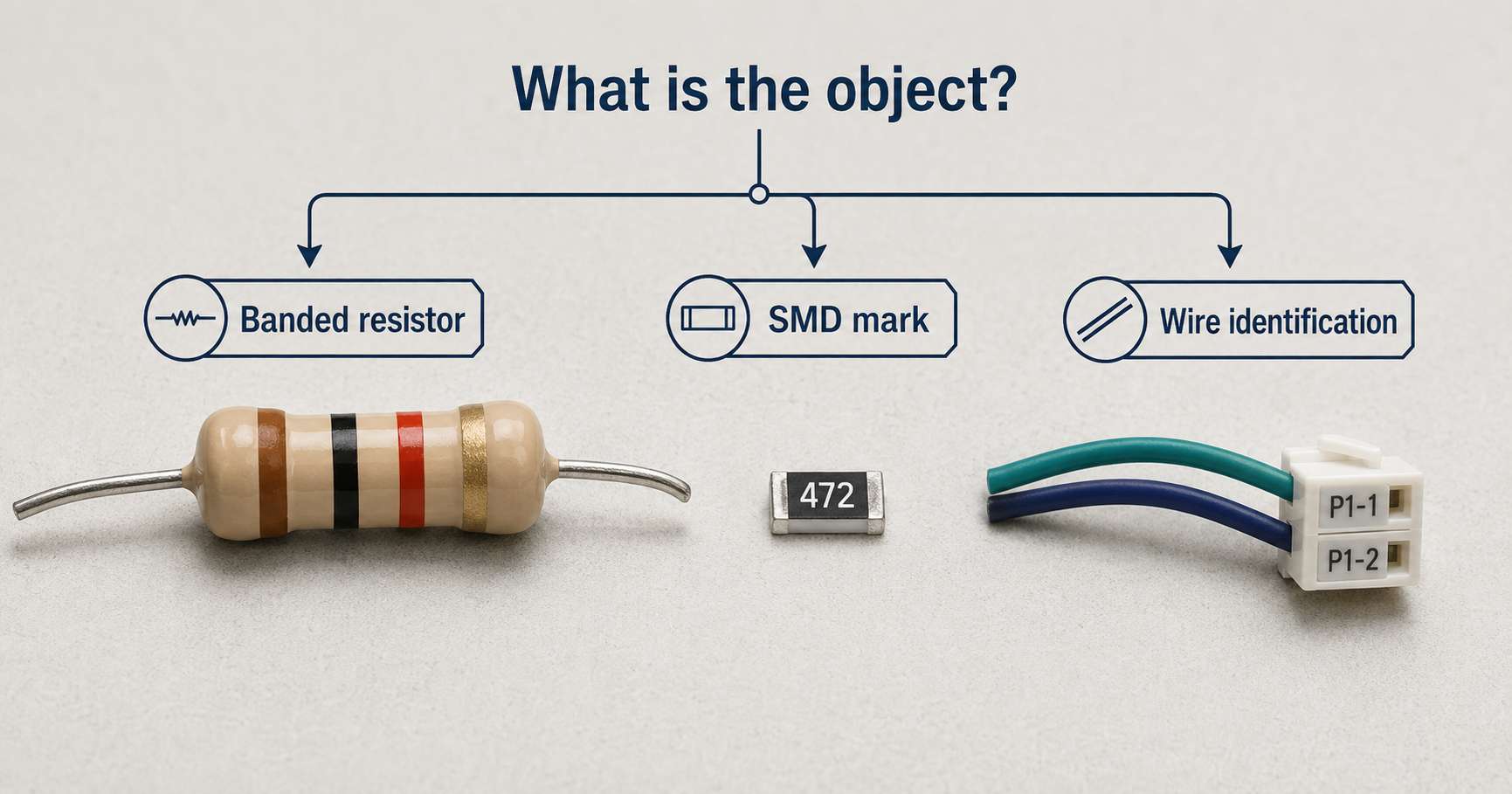
An electronics color code is not a single chart. A component's physical form is taken into account. For example, a through-hole resistor may use colored markings for nominal resistance and tolerance, while an SMD resistor may have printed characters for identification.
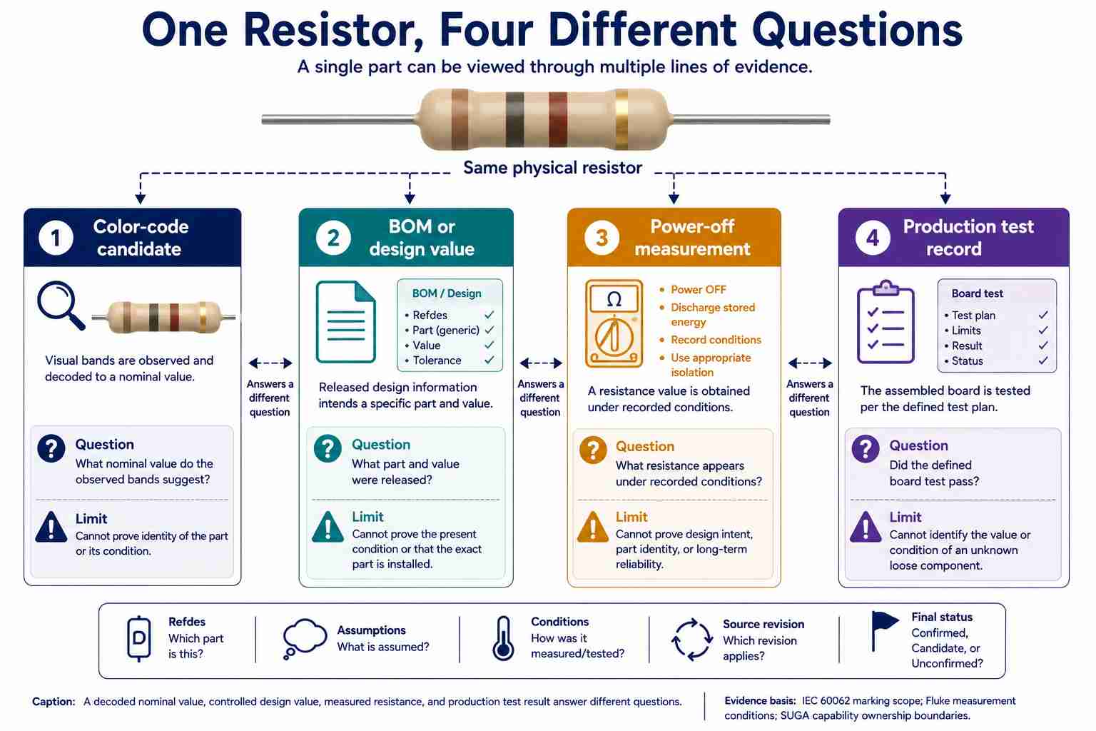
To determine the nominal resistance and tolerance of a banded resistor, first decode its colors and then check whether the visual information provided by the color bands and reading direction is reliable enough to accept the result. If there are conflicts among any of the colors, directions, records, or a safe power-off measurement, you should not use that value until it is confirmed by another method. You can generate precise calculations using an electronic calculator based on visual information that was incorrectly read.
Contents
show
What Does "Electronics Color Code" Apply To?
Resistor and capacitor marking codes are defined within the scope of IEC 60062:2016, while terminal and conductor identification is defined within the scope of IEC 60445:2021. The first general rule is to identify the object first and then read the colors.
The standard low-voltage color codes of red and black provide some clues; however, using these codes as an absolute guide is not acceptable. A repaired harness, custom cable, or undocumented modification can violate the expected color convention. Before confirming any harness or cable assignment, the pin number, endpoint, schematic, and document revision must be verified. AC building or industrial conductors are governed by current jurisdictional rules and qualified local procedures. A resistor color chart has no bearing on the installation or use of these types of conductors or connections.
Which End of a Resistor Do You Read First?
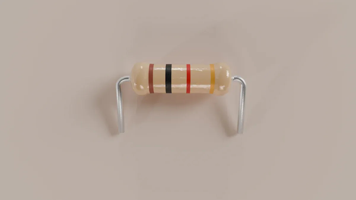
You should begin your initial reading of a resistor from the end that best matches multiple orientation indicators or reference points, instead of using an arbitrary "one slogan fits all" rule. The TE Connectivity resistor color-code reference indicates that end proximity and a larger gap before the tolerance band can help determine the reading direction. These two pieces of information may serve as evidence, but they are not guarantees.
Entering colors into a calculator should follow the process below:
- Verify whether the electrical component in question is in fact a banded resistor and not an axial diode or another marked component.
- Count the number of visible bands.
- Look for the wider gap between the multiplier and the likely tolerance band.
- Check whether the final color can reasonably fulfill its role based on the function of the band and the number of bands.
- If necessary, decode both directions and reject a proposed option if its role is invalid or conflicts with circuit context or controlled records; should both readings remain viable, record the direction as unconfirmed.
However, while many resistors may have gold or silver in the multiplier or tolerance band, it is important never to assume that "gold always fits in the last position" applies to all resistors. Factors such as special products, damaged coatings, close spacing, and extra bands can defeat this shortcut.
Certain types of high-voltage resistors may replace gold or silver with yellow or gray rings due to the metallic components in their lacquer, which may have an effect on their high-voltage behavior. We should consider this an exception for each series type and rely on the manufacturer's datasheet instead of a conventional color scheme.
The way of establishing the reading direction is different from that for electrical polarity. A typical resistor will have neither a positive nor a negative terminal. The direction gives only the interpretation of the markings. The drawings may require that the resistor is used in the same position during inspection and documentation.
The Color Table: Digits, Multipliers, and Tolerance
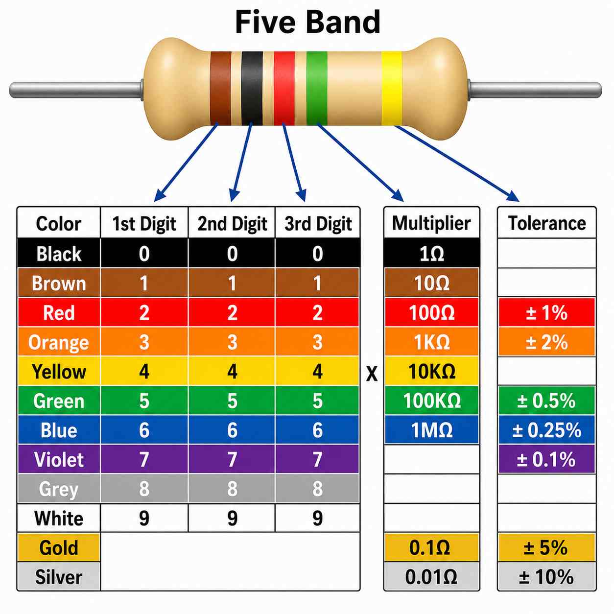
The relationship between nominal resistance and significant digits multiplied by the corresponding multiplier is the main equation. The Vishay Color Code and Standard Resistance Series defines the order of significant digits, multiplier values, and common rules for tolerance. The TCR column includes the most commonly used colors when defining the TCR series of resistors.
Once the nominal value has been established, the next step is to derive the limits by multiplying the nominal value by (1 ± tolerance). For a 5% tolerance, two multiplications are made – first with 0.95 and then with 1.05. The result of this procedure gives the range of allowable resistance surrounding the nominal value. This range cannot, however, provide information about current component readings, establish its health, or identify the exact part number. IEC 60062:2016 introduced pink as a new code for a multiplier of 10^-3, but this does not guarantee that pink is being used universally in every existing category of resistors.
Use a neutral mnemonic for this band only as a recall aid; use the table as the authority during actual identification. Remember black through white as the numbers 0 through 9, and learn gold and silver separately for their roles with respect to multipliers and tolerances.
How Do 3-, 4-, 5-, and 6-Band Resistors Differ?
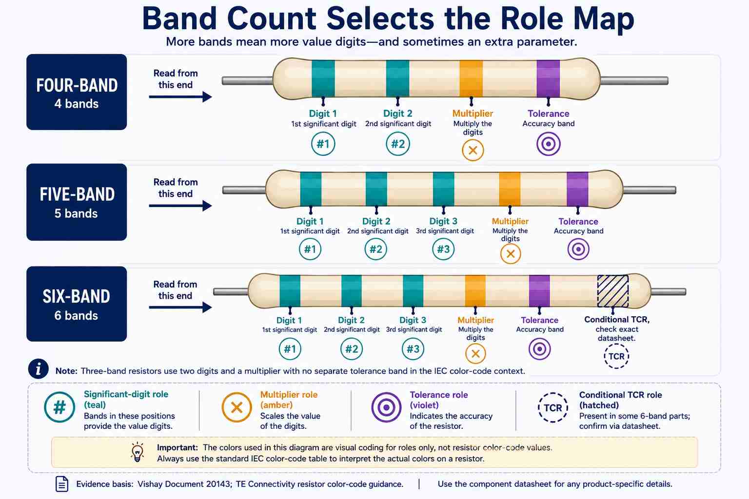
Vishay indicates that four-band resistors have two significant digits, and five-band resistors have three significant digits. Sometimes, the presence of a sixth band gives a TCR. The datasheet of a component, however, will control this additional role as well.
When the component gains a third significant digit, the significant-digit structure changes from 12 to 123. The result is finer nominal-value resolution, not another multiplication step. Also, an unusual extra band will not necessarily be the TCR band; therefore, check the manufacturer series and datasheet when the sequence seems implausible.
For the six-band example, the sequence blue-gray-black-brown-brown-brown is read as 680 × 10 = 6.8 kΩ, with ±1% tolerance and a 100 ppm/K TCR. A TCR coefficient of 100 ppm/K gives a value of 0.01% per kelvin; nevertheless, the datasheet is the authority for understanding how the series specifies and applies TCR.
In some resistor series, there can be one centered black band used to denote a zero-ohm jumper. Thus, the product series should be checked before assigning a one-band marking to a role within the 3- to 6-band structure.
How Do You Decode 100 Ω and 220 Ω Resistors?
The first step is to define the number of bands used and the tolerance of a resistor. This will help avoid the error of interpreting a valid color sequence using the wrong band structure.
Example 1: 100 Ω at ±5%
The brown-black-brown-gold combination on a four-band resistor indicates digits 1 and 0, a ×10 multiplier, and a ±5% tolerance level, leading to a total resistance of 100 Ω that can take a value from 95 to 105 Ω. Using the five-band method, the brown-black-black-black-gold scheme leads to the same 100 Ω value and the same tolerance value, meaning that the resistance may be between 95 and 105 Ω.
Example 2: 220 Ω at ±5%
From a four-band perspective, the red-red-brown-gold combination indicates digits 2 and 2, a multiplier of ×10, and a ±5% tolerance level. Therefore, the resistance in question is equal to 22 × 10 = 220 Ω. With a tolerance applied, the resistance is between 209 and 231 Ω. For a five-band resistor, the red-red-black-black-gold scheme uses 3 digits, a ×1 multiplier, and yields the same values.
Video: How to Read Resistor Color Code – How to Read Resistor Color Code by Electro University. See a beginner-friendly visual demonstration of resistor band reading; use IEC and manufacturer documents for authoritative roles and safe measurement conditions.
When the Bands Do Not Give a Trustworthy Answer
It is impossible to obtain a trustworthy result when the resistance value cannot be determined from visual input because of faded paint, heat damage, dirt, similar colors, even spacing, or an unusual extra band; in that case, keep the result unconfirmed.
A color-code calculator performs a final check on the arithmetic after your color selections, direction selections, and band-role selections have been made. However, it cannot recognize damaged coatings, identify component families, or detect parallel circuit paths. In situations where the calculated and schematic candidates do not match, treat the discrepancy as unresolved rather than averaging the answers or selecting the candidate with which you are most familiar.
Be sure to document the component body through photography prior to removing it from the circuit board. Use diffuse lighting, preserve the lead-side orientation with a reference point on the silkscreen, and use magnification to look for any cracks, burnt areas, loss of coating, partially obscured stripes, or markings, using a grayscale copy if band spacing remains unclear. If the component color is still indeterminate once you've transcribed the color alternatives, do not make an arbitrary decision regarding the correct candidate.
When you are measuring resistance, Fluke recommends that you remove power before taking the resistance measurement and discharge capacitors where applicable. Since in-circuit parallel paths have the potential to change the readings during measurement, you may need to lift one lead or remove the component from the circuit in accordance with the applicable procedure. If you cannot establish the component to be in a safe and de-energized state, do not proceed.
All information concerning service or manufacturing should be stored, including the text value, reference designator, observed color bands, known part number, revision of the document, and the conditions under which the readings were taken; this will allow future checks not to rely solely upon your perception of color. Refer to the separate multimeter symbols guide for meter modes, jacks, displays, safety markings, and other associated symbols.

Can Wire Colors or SMD Marks Use the Same Chart?
No. Wire colors and most SMD markings do not use the axial resistor color chart. In general, many SMD markings follow numeric or letter-based formats. Smaller components may not have any visible markings; however, the manufacturer and package context will provide insight into which system applies to a given component.
For example, an SMD resistor in numeric form shows 103 as 10 kΩ and 472 as 4.7 kΩ. In four-digit form, SMD resistors use three significant digits with the fourth digit being a power-of-ten multiplier.
RKM notation uses the letters R, K, or M in place of a decimal point or value scale. For instance, 1R0 represents a 1.0 Ω value, whereas 1K5 indicates a 1.5 kΩ value when applied to this marking convention. This short summary does not provide decoding for EIA-96, and parts with very limited markings will need package details, circuit context, and BOM verification to determine the exact part number. Surface-mount component reference materials provide a more extensive guide for identifying surface-mount devices.
Capacitors, inductors, and diodes may also use printed markings or color codes. Once the component family is identified, find a suitable manufacturer or standard reference for that component. For example, a red resistor band does not necessarily serve the same function on a molded axial inductor. A molded axial inductor may use the same black-through-white digit colors and the same digit-times-multiplier arithmetic as listed in this article, but the result is read in microhenries rather than ohms, and the tolerance-band colors are not guaranteed to represent the same percentage in both systems. An ordinary-looking resistor must first be confirmed as a resistor or molded axial inductor to avoid reading the correct color sequence in the wrong unit.
Insulated wire uses a different identification method. The color code may indicate that a low-voltage red or black conductor follows a project convention; however, verification should be made against project specifications, schematics, connector pinouts, harness drawings, and revisions. Building and industrial wiring depends on jurisdiction, installation requirements, and equipment documentation. A component-value chart should never be used for rewiring or energized electrical work.
References & Sources
- IEC 60062:2016 Marking codes for resistors and capacitors – IEC
- IEC 60445:2021 Basic and safety principles for man-machine interface, marking and identification – IEC
- Resistor Color Codes: What Do the Color Bands Mean? – TE Connectivity
- Color Code and Standard Resistance Series – Vishay
- Decoding Resistors: 10K, 220 Ohm, and More – Tom's Hardware
- Resistor Color Codes – Science Buddies
- How to Measure Resistance – Fluke
- Resistor Color Codes: Color-to-Value Correspondence Chart – Panasonic Industry
- Complete Guide to Interpreting Chip Resistor Resistance Markings – Panasonic Industry
- SMM0207 Thin Film MELF Resistors – Vishay
- VR25, VR37, VR68 High Ohmic / High Voltage Metal Glaze Resistors – Vishay