Upload BOM & Gerber

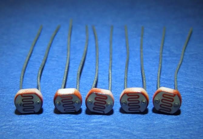
An LDR is a passive electrical component whose resistance changes with incident light, also referred to as a photoresistor or photoconductive cell. For example, typical CdS light dependent resistors have lower electrical resistance under increased illumination. Cadmium sulfide light dependent resistors can be used for relative light measurement but cannot directly output a calibrated lux value, logic state, or digital signal.
The response characteristics of an LDR vary based on the construction of the LDR itself, the wavelength or spectrum of incident light, the ambient temperature, the history of prior illumination, and the geometry and timing of the LDR when illuminated by a light source.
- An LDR is an electronic component that detects and responds to changes in incident light intensity through changes in resistance. CdS LDR sensors generally decrease in resistance as light intensity increases, but their actual response should be tested for the intended application.
- A raw LDR does not directly produce a calibrated lux value, logic state, or digital signal; the surrounding circuit must convert and interpret its resistance.
- Other devices with improved performance include photodiodes, phototransistors, and ambient-light sensors; use of these devices is recommended for applications requiring defined lux values, rapid response, or tight spectral performance.
Contents
show
What Is a Light Dependent Resistor?
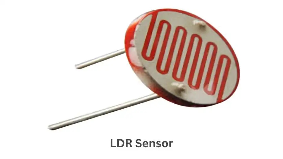
An LDR is an electronic component that detects changes in incoming light intensity through a continuous change in resistance. LDRs are commonly referred to as photoresistors, photoconductive cells, or LDR sensors.
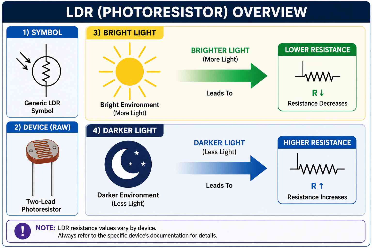
The term “LDR sensor” has been used interchangeably to describe small electronic modules that combine an LDR with a fixed resistor, a comparator, or a potentiometer. A raw two-terminal LDR, by itself, does not produce a voltage or a digital output. It is only when it is incorporated into an electrical divider or module circuit that these functions take place.
The Advanced Photonix family of light-sensitive CdS materials responds to visible light, usually with a decrease in resistance as the light level increases, but this does not follow a universal or linear lux scale. Materials, tolerances, source spectra, operating temperatures, and optical histories of two LDRs may differ enough that the same nominal illuminance will give different resistance values. For this reason, the most reliable designs will be based on the actual performance of a specific LDR product under a specified set of optical conditions instead of just one generic LDR resistance value.
In practical terms, LDRs can fill three major functions. First, relative measurements keep track of whether light levels have climbed or fallen across a known range. Second, threshold detectors determine whether a controlled limit has been crossed. Third, change detectors monitor changes without making claims about specific absolute illuminance. The same sensor could serve all three functions, but the methods for achieving these goals impose different requirements on the dividers, ADCs or comparators, timing, and calibration methods.
How Does a Light Dependent Resistor Work?
The basic principle that governs the operation of an LDR is photoconductivity. The light-sensitive material of an LDR contains electrical charge carriers. When photons that contain enough energy are absorbed by the material, the number of available carriers for conduction increases; therefore, the conductivity increases and the electrical resistance decreases. Conversely, when the amount of illumination decreases, the number of available carriers will also decrease, and the electrical resistance will increase. Consequently, a typical CdS photoresistor will exhibit a change in resistance from many kilohms while illuminated to several hundreds of kilohms or several megohms while in darkness.
Because the relationship between lux and ohms is not an ideal linear conversion, the photoconductivity of an LDR depends on both the light level and wavelength of the light. Recovery time for an LDR following a sudden change in illumination level can also be significant, and a change in temperature or incomplete recovery from previous illumination can also affect the resistance of an LDR. Also, data derived from one LDR family should not be used as a transfer function for another LDR family; therefore, the initial design should be based on the appropriate datasheet performance curve for the particular light-sensitive application being designed. Once the actual sensor assembly is created, it should be characterized under the actual optical conditions that will be present in the application, including spectrum, geometry, and timing.
How Is an LDR Constructed?
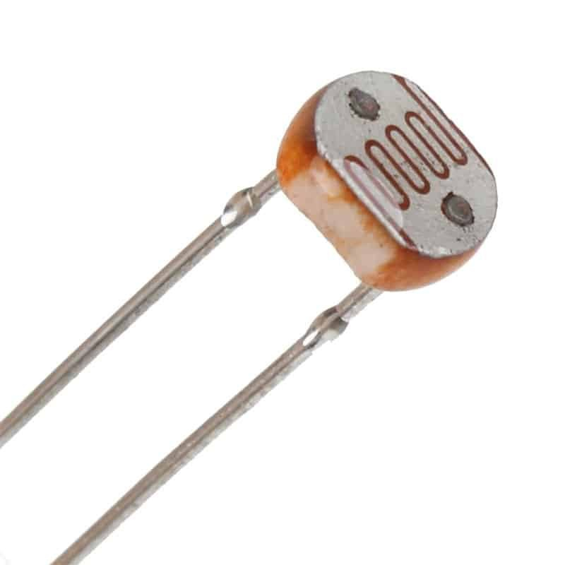
A through-hole photoresistor has two terminals attached to a photosensitive layer on an insulating support and usually has a serpentine or interleaved configuration; thus, it has a fairly large active area while still keeping the electrodes electrically isolated from each other. A transparent or translucent protective material is usually applied to the sensing surface.
Commercially produced photoresistors can be packaged on a ceramic header, in a plastic package, or in a sealed metal package, depending on the conditions to which the photoresistor will be exposed and the reliability requirements of the application.
Since both the electrical response and the optical path of the photoresistor depend on the interaction of light with the sensing area, the package opening, orientation of the sensing area, type of enclosure window, angle of light hitting the sensing area, dust or other contaminants on the surface of the sensing area, and the use of light pipes all impact the amount of light that actually reaches the active material of the device.
Simply knowing the physical appearance of a photoresistor will not provide enough information regarding the footprint, process temperature, moisture protection, or optical performance; these details must be gathered from the documentation of the purchased component.
What Types of LDR Are There?
Intrinsic Photoresistors
Textbook classifications often distinguish two types of photoresistors: intrinsic and extrinsic. In an intrinsic photoresistor, light generates carriers within the base semiconductor material. Its behavior is strongly influenced by the material and the photon energy required to generate mobile carriers.
Extrinsic Photoresistors
In an extrinsic photoresistor, controlled impurities or material modifications alter the wavelengths and energy levels to which the device responds.
The classification of a photoresistor as intrinsic or extrinsic is useful for understanding how photoconductive devices operate; however, this classification should not be used as an easy way to choose a commercially available photoconductive device. In addition, it does not define accuracy, speed, resistance range, temperature behavior, or the correct divider value of the photoresistor. In practical applications, the properties listed in the material declaration, spectral characteristics, resistance characteristics, response time, packaging, and component revision are all much more important than using the intrinsic or extrinsic classification name.
What Does the LDR Symbol Mean?
The LDR symbol is the familiar illustration of a simple resistor with arrows indicating light approaching the resistor. In a typical two-terminal photoresistor, both terminals are non-polarized, so either terminal can be connected to either end of the resistor arrangement. An LDR module differs from a simple photoresistor. When you add VCC, ground, and output pins, the functions of the pins must be defined. Therefore, analog or digital refers to the signal chain surrounding the LDR module rather than the bare LDR itself.
Which LDR Specifications Matter Most?
LDR specifications are most useful when you know the conditions under which these specifications were determined. The illuminance and type of light source used, the ambient temperature, the length of dark adaptation, previous exposure, and the family of the LDR can all affect the circuit’s performance. A single resistance value will not be sufficient to determine the divider range, switching margin, timing, assembly process, and acceptance criteria for a photoresistor.
The Advanced Photonix PDV-P8001 Rev. B specifies a resistance range of 3 kOhm to 11 kOhm when tested at 10 lux, 2856 K, and 25 degrees C, and a minimum dark resistance of 0.2 MOhm after completion of the dark test outlined in the datasheet. In a similar manner, a typical rise time of 50 ms and typical fall time of 20 ms under the specified optical conditions are provided by this revision. The NSL-4910 Rev. A lists a minimum dark resistance of 560 MOhm, demonstrating that there is a wide variation in dark resistance across device families. The NORPS-12 specifies resistance values of 5.4 kOhm to 12.6 kOhm under 1 foot-candle (approximately 10.76 lux) at 2854 K, with a minimum dark resistance of 1 MOhm measured 15 seconds after removal of the test light and a typical spectral peak of 550 nm.
These examples represent possible values and not preferred operating points; the selected part may also impose voltage, power, temperature, and soldering restrictions. In addition, when it comes to CdS cells, cadmium adds another layer of compliance checking, as the European Union’s RoHS restrictions specify a maximum concentration value of 0.01% by weight in homogeneous materials for cadmium and its compounds, subject to the requirements of the directive and applicable exemptions. Therefore, compliance must be checked through the exact material declaration, use case, and intended destination market rather than through a generic photoresistor description, historical exemption, or inferred compliance.
How Does an LDR Voltage Divider Work?
An ADC or comparator requires a voltage signal, and a fixed resistor together with an LDR usually forms a voltage divider. The position of each resistor determines the direction of the voltage signal. When the LDR is connected to VDD and the fixed resistor is connected to ground, as the brightness of the light increases, the LDR resistance decreases and the midpoint voltage rises. If the two components are connected in reverse, the midpoint voltage drops as the brightness of the light increases.
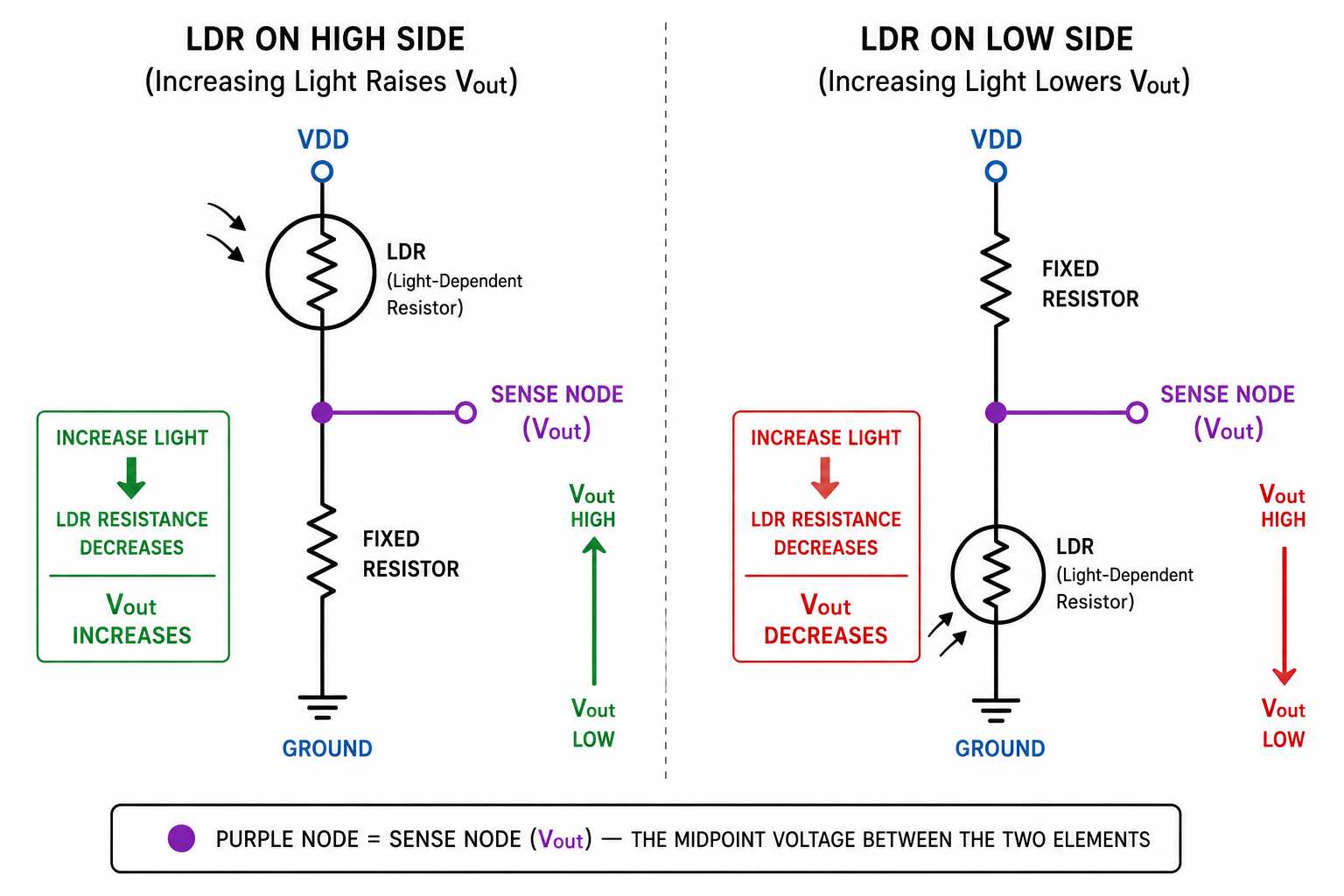
An LDR that is connected to VDD and a fixed resistor that is connected to ground has the following relationship:
Vout = VDD x Rfixed / (RLDR + Rfixed)
Conversely, the relationship is:
Vout = VDD x RLDR / (Rfixed + RLDR)
Be sure to label VDD, the midpoint, and ground before assigning any ADC or comparator inputs. This will prevent an endpoint of the divider from being mistaken for a useful sense node and will clarify the required logic direction before the firmware or comparator polarity has been determined.
How Do You Choose the Fixed Resistor?
Begin with the window between dark and bright resistance that is needed by your product to distinguish the two. If your goal is to maximize the ideal voltage difference between the two resistance endpoints, you can make a reasonable first approximation using the geometric mean:
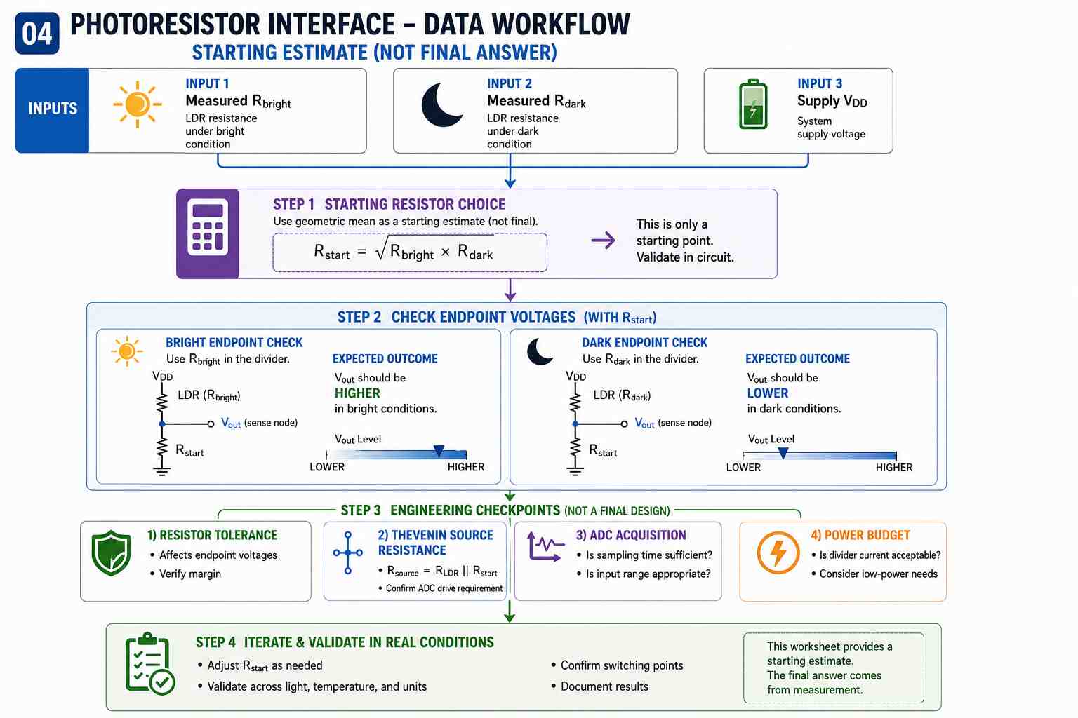
Rfixed = sqrt(Rbright x Rdark)
This equation serves as a mathematical starting point. This is not intended to represent a manufacturer’s recommendation. There are numerous factors that could alter the final value of the fixed resistance, such as threshold position, preferred resistor values, resistor tolerance, sensor spread, optical losses, temperature, ADC requirements, and hysteresis.
Worked Divider Example Using NORPS-12 Data
Assume a 3.3 VDC system that is using an LDR on the high side of a voltage divider and that a conservative approximation of the starting calculations gives you the following: 12.6 KOhm for Rbright (maximum light-resistance specification at 1 foot-candle) and 1 MOhm for Rdark (minimum dark-resistance specification taken after 15 seconds).
Using these values, we can calculate the expected geometric mean at about 112 KOhm; thus, we can evaluate a rough estimate with a standard value of approximately 110 KOhm.
At 110 KOhm, the ideal voltage in the brighter state is approximately 2.96V. Using the 1 MOhm dark resistance, the ideal voltage in the darker state is approximately 0.33V, which means that the endpoint span is approximately 2.63V. Since the value of 1 MOhm is a minimum dark-resistance value, the actual dark-state voltage will likely be lower when the resistance is higher than the 1 MOhm example value.
Because of this, it is critical that we select the resistor from the actual sensor endpoints instead of selecting one from a standard comparator circuit based on example voltages. We must also include sensor tolerance, window loss, temperature effects, ADC error, noise, and hysteresis when determining the final threshold limits.
How Do You Prevent Threshold Chatter?
A divider voltage that moves too slowly or is too noisy can “chatter” across a threshold and cause repeated switching of the light. Therefore, we need to set hysteresis so that separate rising and falling thresholds prevent repeated switching around a single threshold. A good example is a controller that turns lights on when the light level reaches a specific threshold and requires a clearly brighter light level to turn the same light back off.
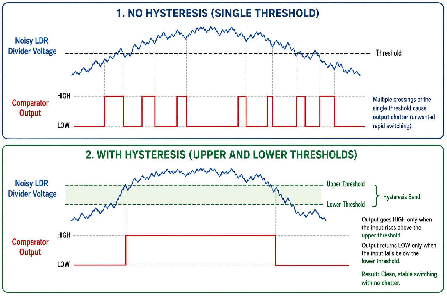
The required hysteresis difference should come from actual testing of electrical noise, variations in the optical level, component tolerances, and expected switching performance. It is not appropriate to copy or guess at trigger networks based on a comparator from other sources.
With an ADC path, it is possible to obtain continuous values from the resistance-derived signal, which may be used for averaging, calibration, diagnostic purposes, and deciding how firmware will take action. A comparator produces a hardware state from the same continuous signal. The choice is based upon the application; both approaches can coexist within the same application. The LDR remains a continuous resistance-based component regardless of whether its signal is measured by an ADC or interpreted by a comparator.
Where Are LDRs Used?
Automatic Dusk-to-Dawn Lighting
An automatic night light or a light fixture that operates at night uses an LDR to detect dusk/dawn transitions. The voltage output produced from the divider circuit is determined by the amount of ambient light in the vicinity of the light fixture. The output can then be used to determine when a relay, MOSFET, or driver is used to turn the light fixture on or off based on the light threshold.
To ensure that the light fixture does not rapidly cycle on or off at daybreak, sunset, or whenever shadows pass by, the design must incorporate threshold margin with respect to dusk and dawn. The LDR must also be positioned so that the light fixture does not shine directly into it or produce optical feedback.
Beam-Break and Security Detection
A light beam aimed at an LDR can produce a large resistance change when the beam is interrupted. Therefore, this can be used for simple object detection, door alarms, counters, and presence detection for events of modest speed.
However, reliability for light-beam detection is dependent upon other factors such as ambient sunlight, alignment of the LDR sensor to the beam source, dust accumulation on the LDR, contaminant build-up on the window, aging of the light source, and the LDR response time. The design should measure the clear-beam and blocked-beam states under realistic conditions and set the threshold within the available margin instead of assuming that any visible shadow will reliably trigger detection.
Display and Ambient-Light Adjustment
LDRs provide an inexpensive source of relative ambient-light readings and allow users to dim displays, adjust display brightness, and control other user-interface lighting. The actual resistance response may vary with the enclosure window’s tint, thickness, angle, and infrared transmission, so an LDR should not be treated as a calibrated light meter that directly measures ambient light in lux.
Audio and Optically Controlled Circuits
In addition to ambient-light measurements, CdS photoresistors have also been used in optically controlled audio circuits and in products as a means of controlling gain based on changes in light intensity. Due to the slow response time of a photoresistor (CdS), it may provide inadequate detection of fast-moving events; in some situations, however, a more gradual control of gain can be desirable. Advanced Photonix provides a listing of audio compressors in its catalog of products for the NSL-4910 line.
When Is an LDR a Good Choice?
An LDR can be an attractive choice when designing systems or devices where low-cost passive sensors are required; these designs typically require significant changes in resistance when exposed to light, an easy-to-use divider interface, and modest response speed. Applications for LDRs are particularly suitable for relative measurements, day/night decisions, slow optical changes, and simple threshold measurements where unit-to-unit variation can be addressed through margin, calibration, or adjustable limits. The two-terminal interface also creates a simpler front end to the circuit.
The resistance versus light-intensity curve is not linear across all devices, and the spectral response of an LDR is often different from a calibrated photometric curve. Additionally, significant differences in device temperature or previous light exposure can affect the resistance measurement. In some instances, the response or recovery time will not be fast enough to measure transient events. In addition, some components such as CdS may have material-compliance constraints. When accurate lux measurement, fast pulse detection, strong rejection of infrared energy, narrow spectral selectivity, or interfacing with a digital host is required, other architectures may provide less calibration effort and uncertainty.
What PCB and Optical Details Affect an LDR?
The divider sense node should be treated as an analog signal, kept reasonably short, and separated from noisy switching nodes. Use an appropriate grounding/reference strategy, and add filtering only when the expected signal bandwidth allows it. The divider will have a condition-dependent Thevenin source resistance, which may affect a high-resistance divider when interfaced with the MCU ADC sample-and-hold network. Microchip ADC guidelines show that the relationship between source resistance and acquisition time is not universal for all MCUs and must be verified for each device. If the divider impedance is too high to meet sampling requirements, using a buffer can help, but it will also add offset, noise, power requirements, cost, and circuit complexity.
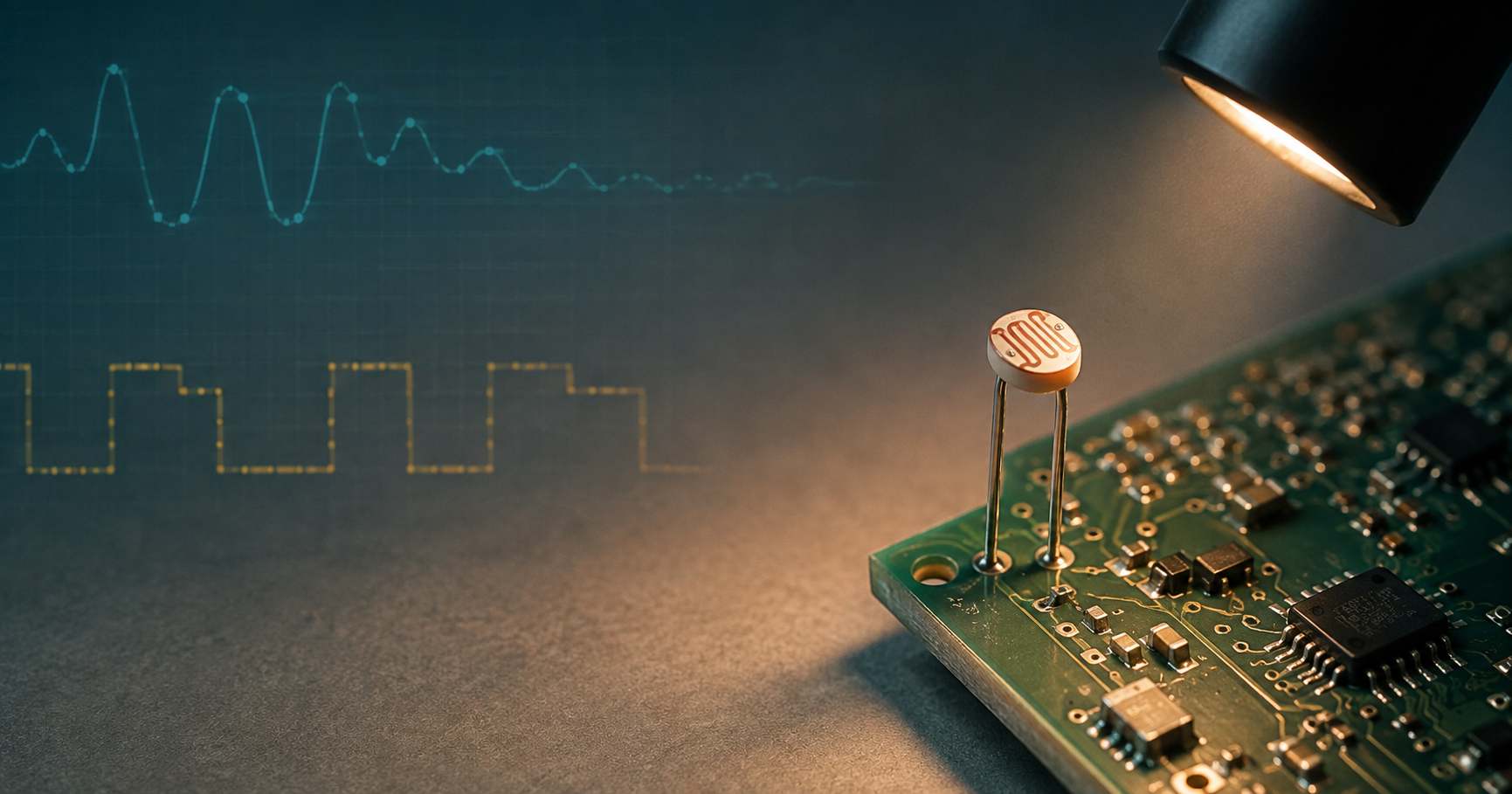
The optics of the design must also be carefully considered, including where the sensor will be located in the enclosure, the sensing opening, optical keep-out region, expected contaminants, light angle, and the types of light sources located near the LDR. A status LED can produce direct light on the sensor, reflect from the enclosure housing, or couple through a light pipe, shifting the threshold value from what may have been considered stable while testing in open air.
How Do You Test an LDR in the Finished Assembly?
To test an LDR in its final assembly, the sensor must be tested under controlled and repeatable optical conditions and controlled electrical conditions; repeated testing of the sensor after assembly of the enclosure is essential. Testing an LDR by using a hand to cover the sensor or by shining a flashlight onto the sensor will demonstrate that there was a change; however, it will not define a resistance band, voltage threshold, response time, temperature margin, or immunity to the product’s own illumination.

To compare the bright and dark resistance states, the resistance value should be measured after power is removed and stored energy is safely discharged. In a powered circuit, measure the voltage or record the ADC codes from the divider’s midpoint. To recreate these results later, use a stable light source and record the geometry of the test setup.
Check the electrical direction and endpoint span using a bare divider; after that, utilize the actual window and enclosure and then perform the entire optical verification process again. Also, during your second verification process, you should turn on any nearby indicators as well as any applicable loads. Doing this will help you determine whether your problem is in the wiring or resistor selection, or if it may be due to a problem with the enclosure or optical feedback from self-light. Although calibration can help correct for an offset within a specified range, it cannot compensate for inadequate ADC span, excessive optical feedback from an uncontrolled source, or a sensor that is too slow to detect the event of interest.
LDR vs Photodiode, Phototransistor, and Ambient-Light Sensor
A photodiode offers fast optical current output with defined conditioning requirements; a phototransistor provides gain for switching purposes or optical detection applications; and lastly, an integrated ambient-light sensor can provide a calibrated digital output with controlled spectral behavior.
An example of how the requirements change from relative light measurement to ambient-light measurement is provided by the Texas Instruments OPT3001. The OPT3001 measurement range is 0.01 lux to 83 k lux. Typical infrared rejection greater than 99%, a typical operating current of 1.8 microamps, and a supply voltage range of 1.6 V to 3.6 V allow the sensor to provide a spectral response close to that of the human eye. An I2C-compatible digital output means that you can communicate with the sensor digitally on your board or device. However, it is not a universal replacement for an LDR; instead, it shows how much better suited an integrated ambient-light sensor can be when the requirement is defined in absolute lux values rather than relative resistance.
Frequently Asked Questions
Q1. Is an LDR analog or digital?
By itself, the LDR is a variable-resistance component that you turn into an analog voltage with a resistive divider. You can, with the use of a comparator or firmware threshold, convert that analog voltage to a digital on/off signal.
Q2. Does an LDR have polarity?
LDR modules typically have defined terminal assignments for VCC, ground, analog-output, or digital-output because they contain additional circuitry. However, a conventional two-terminal LDR component itself does not have a specific polarity.
Q3. Does LDR resistance increase or decrease with light?
In the case of the common CdS photoresistors discussed here, resistance decreases with an increase in light level. However, the exact resistance will be different for different devices and is influenced by test conditions.
Q4. Can an LDR measure lux accurately?
Not by itself. The LDR provides a resistance that is device-dependent, nonlinear, and spectrum-dependent. While it is possible to calibrate an LDR for a particular application, an integrated ambient-light sensor would generally be a better choice for applications requiring absolute lux values across changing lighting conditions.
Q5. Why can an LDR circuit flicker near dusk?
The flicker associated with dusk is typically due to minor variations in the input signal from a variety of sources, including noise, cloud cover, system reflections, component tolerances, or slow sensor settling. Thus, the output can fluctuate repeatedly around a single threshold. To reduce the likelihood of output flicker, separate rising and falling thresholds, time qualification, or both are usually applied.
References & Sources
- Light Dependent Resistor (LDR) – Advanced Photonix
- PDV-P8001 Rev. B datasheet – Advanced Photonix
- NSL-4910 Rev. A datasheet – Advanced Photonix
- NORPS-12 CdS Photocell datasheet – RS Online
- AN990 – Analog Sensor Conditioning Circuits – An Overview – Microchip
- AVR127 – Understanding ADC Parameters – Microchip
- TIPD144 – Comparator with Hysteresis Reference Design – Texas Instruments
- OPT3001 – Digital Ambient Light Sensor – Texas Instruments
- RoHS Frequently Asked Questions – European Commission
- LDRs Explained: The Semiconductor Component That Reacts to Light – ElectronicsNotes