Upload BOM & Gerber

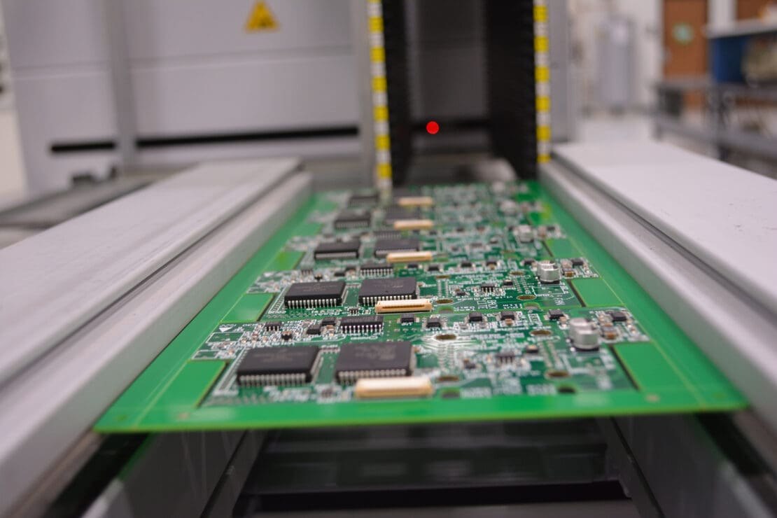
Aerospace PCB Assembly has specific PCBA manufacturing program requirements, rules on providing evidence, and defined approval authority.
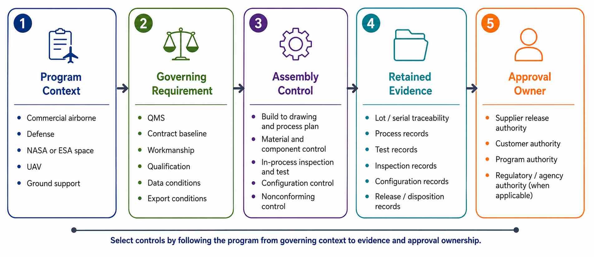
The equipment you are already using does not provide proof that a common acceptance standard exists across multiple aerospace industries. Different programs may have their own baselines, verification plans, and change authority, and may describe their work differently, such as Civil Airborne, Defense, Space, UAV, or Ground Support.
- Aerospace is a program context.
- QMS, workmanship, inspection, functional testing, and qualification evidence answer different questions for quality processes.
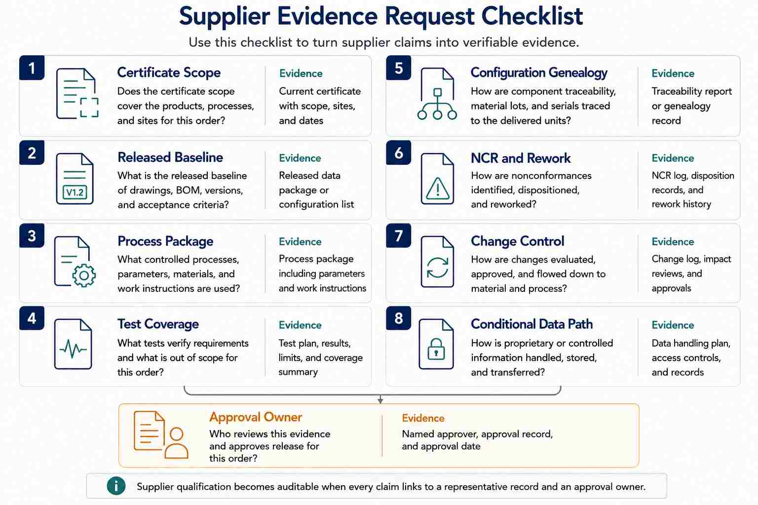
- Approval of a supplier must provide linkage between the released baseline and records of processes used to produce that product, test coverage, genealogy of components used, controlled changes to the products, non-conformance disposition, and a named individual releasing the product.
- The materials, stack-up configuration, assembly route, coating, and test coverage must all follow the requirements for the mission environment and the requirements published by the program; laminate, solder alloys, coatings, and acceptance classes are not universal for aerospace qualification.
Contents
show
What Makes PCB Assembly Aerospace-Specific?
PCB assembly becomes aerospace-specific by introducing configuration control, verification, and release ownership into the program. The simplest definition for why configuration control, verification, and release ownership exist is that the approved product data must be linked to the produced hardware and retained as evidence of compliance with program requirements.
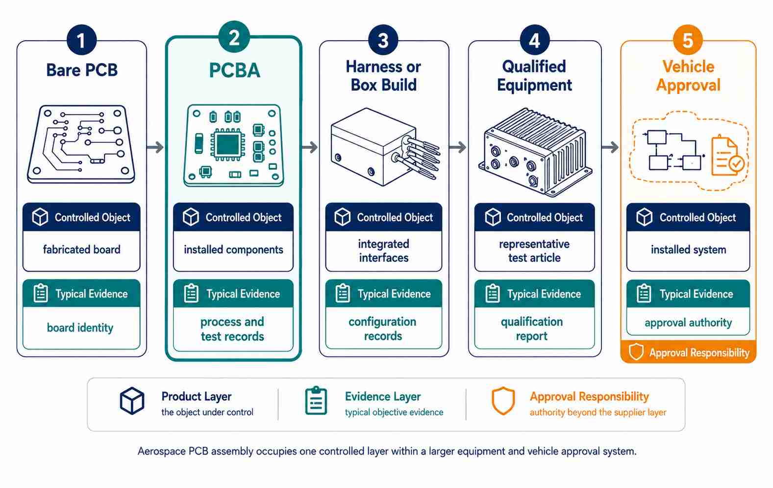
For example, suppose a supplier provides a PCBA that incorporates a wiring harness and machined enclosure, but the customer assumes the delivery note is representative of the completed box's vibration and thermal qualification; in reality, the evidence provided by the assembly supplier may not reach that level of completeness. The documents may identify the CCA instead, but that term alone does not indicate what is actually being provided versus what should be expected.
The difference between CCA and PCBA terminology highlights this nuance, as do the various assembly routes available, including SMT, through-hole, and mixed assembly. Each assembly route will have different package geometry, thermal mass, mechanical support requirements, interface requirements, and inspection access. Aerospace controls begin when the selected route is connected to the applicable criteria, required evidence, and approved change process.

Which Program Requirements Apply to Your Assembly?
The program for which you are building determines the applicable standards. For example, a supplier that provides the same document list for Commercial Avionics and Government/NASA programs cannot accurately identify what is acceptable because the controlling requirements differ between programs.
Specifically, for assemblies built, tested, and released under one program versus another, the program, authority, contracting agency, and installation location determine the applicable requirements.
Separate the evidence layers
There are different sources for each layer of evidence: airworthiness certification, mission assurance, source approval, ECSS tailoring, export jurisdiction, CUI marking, technology status, deviation authority, and flight release. Interchangeable badges hide who the decision maker is, because an AS9100 certificate represents an organization-level question. The IAQG 9100 description provides QMS requirements for aviation, space, and defense organizations; the IAQG certification program uses OASIS for status and audit information. Verify the site and scope, and verify the standard and current status. The organizational record cannot qualify a flight hardware item.
IPC-A-610J answers a different question: it provides acceptability criteria for electronic assemblies. The electronic assembly standards catalog defines J-STD-001J as specifying soldering process and material requirements. A contract determines the revision, class, addendum, precedence, and customer requirements. Neither document establishes installed equipment performance.
Another layer of evidence comes from FAA guidance. AC 21-16G recognizes RTCA/DO-160 revisions D through G as an acceptable means for environmental qualification of airborne equipment. AC 21-16G states that it is one of a number of acceptable means of compliance a program may select. AC 20-152A addresses airborne electronic hardware design assurance; AC 20-152A does not address EMS factory certification.
A space program has different requirements. NASA-STD-8739.6B applies within NASA mission-hardware governing documents. ECSS-Q-ST-70-12C Rev.1 permits project tailoring; combining them does not produce a universal checklist.
Keep data and export questions conditional
Keep information about data and export controls conditional based on contracts and jurisdictions. NIST SP 800-171 Rev.3 addresses confidentiality in nonfederal systems. The DDTC Registration Guide states that registration does not grant export, temporary-import, or brokering privileges.
How Do Mission Conditions Change Assembly Controls?
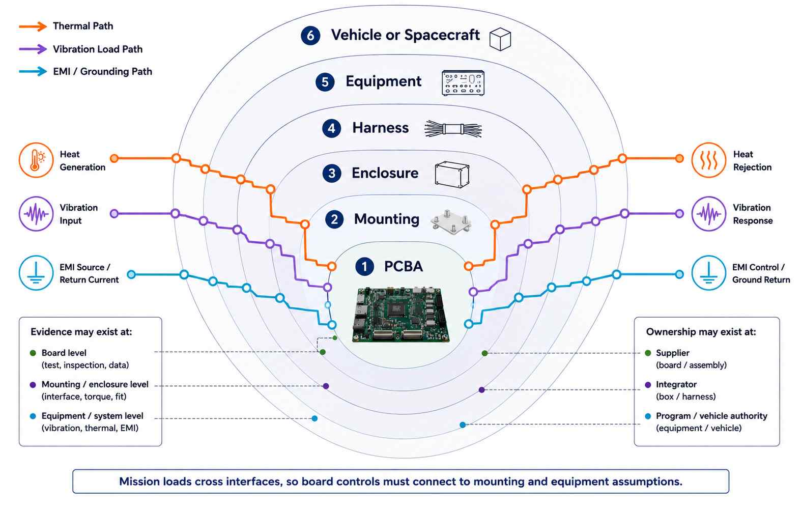
Control over the assembly for a mission condition is established after a program has defined its profile and system boundary. User requirements specify the mounted configuration and operating state. They identify the specimen to be used, limits, acceptance criteria, result, and approver. Terms like rugged, harsh, and space-grade do not identify the essential requirements.
A test plan that outlines a requirement for the item to survive launch vibration and meet qualification does not provide adequate direction to the laboratory. Required details include thermal-vacuum sequencing, component mounting response during the test, harness behavior, genealogy of each component, coating cure, etc. Each of these areas must have independently defined verification evidence fields, and each area may also require different specimens, instruments, and acceptance logic. A single generic test campaign does not adequately support the items being tested. Use precise verification terms. Terms such as exposure, susceptibility, endurance, margin, screening, acceptance, qualification, validation, and certification are not interchangeable. Each of those terms can imply the need for different specimens or differ in authority.
An executable plan will also define the preconditioning, ramp rate, dwell, axis, spectrum, telemetry, fixture fidelity, calibration, measurement uncertainty, abort thresholds, anomaly disposition, and recovery procedures. If these areas of concern are not detailed, the nominal profile will not convey a clear indication of the requirements and may lead to ambiguities during the purchase request phase.
Materials that support the mission analysis: No laminate, solder alloy, coating, adhesive, connector, or component is considered to be universally aerospace-qualified; rather, selections made for each type of material will depend on many factors including the design, procurement rules, the environment in which the material will operate, compatibility with the manufacturing and repair processes, and the basis for qualification of that material. The NASA Outgassing Database provides support for vacuum material screening but does not provide qualification for the assembled PCB or equipment. Conformal coatings and potting compounds can serve to limit environmental exposure of the assembly; therefore, it is critical that the evidence associated with PCB protection documents the material, cleanliness of the PCB, masking methods utilized to protect the PCB during the process, application processes, curing processes, inspection procedures, and reworking procedures.
The validation of the product also must include the connectors, seals, thermal paths, service openings, and operating environment.
How Should Materials and PCB Architecture Follow the Mission?
You should select the materials based on the released stack-up and mission profile, not a label such as “aerospace-grade.” Useful comparison fields include Tg, Td, CTE, Moisture Absorption, Dielectric Constant and Loss, Thermal Conductivity, Copper Weight, Surface Finish, Outgassing Requirements, and compatibility with the planned soldering and repair process. The industry standard ECSS-Q-ST-70-12C Rev.1 treats rigid, flexible, HDI, and RF PCBs within the same design-rule framework, which illustrates the reason that you cannot select a laminate based on just one property. Materials with higher Tg values can still differ substantially in moisture absorption, Z-axis expansion, dielectric performance, and thermal conductivity.
Representative values illustrate the trade-offs described in ECSS-Q-ST-70-12C Rev.1. The Polyimide/Glass example indicates a substantially higher Tg than the High-Tg Epoxy example; however, the Polyimide/Glass example also absorbs nearly twice the amount of moisture — which is a critical parameter associated with outgassing and dimensional stability after the PCB has been placed in a vacuum environment. Conversely, for the Ceramic-reinforced PTFE example, the trade-off demonstrated is extremely low moisture absorption and CTE, but with the processing and cost considerations that accompany PTFE systems.
Table 6-1 of the ECSS-Q-ST-70-12C Rev.1 document contains representative examples that may be used for comparison purposes, but they do not define the material properties that must be used in all programs.
A specific supplier’s data sheet should be seen as additional information used in the assembly’s validation and does not create a requirement to meet contract specifications. As an example, Isola P95/P25 specifies Tg 260°C, Td 416°C, and capability for six 260°C reflow exposures; however, this information is about this laminate system and does not validate its use on any particular aircraft or spacecraft. The engineering team must continue to perform due diligence in ensuring that electrical performance, thermal cycling, moisture or vacuum behavior, stack-up, fabrication capability, heat exposure during assembly, repair strategy, and qualification basis are addressed when making engineering and manufacturing decisions.
PCB architecture includes design considerations such as controlled impedance and return-path continuity; however, some considerations apply specifically to the assembly, such as the way a heavy component may be mounted. Heavy components and connectors can require planned restraint to minimize vibration effects on the assembly; HDI and rigid-flex configurations can reduce interconnect count and mass but have added fabrication, assembly, inspection, and rework considerations that must be reviewed. As with other aspects of aerospace production, the assembly vendor should maintain the released geometries and process assumptions rather than substitute a generic “ruggedized” construction.

What Does a Controlled Aerospace Assembly Flow Include?
The physical processes associated with assembling SMT boards, through-hole parts, mixed assembly, cleaning, coating, inspection, and testing are familiar, but aerospace work becomes different when each significant operation is tied to an approved configuration and retained evidence. Before materials are assembled or used, contract review must resolve the applicable drawings and BOM revisions, approved manufacturers and sources, substitutions, workmanship standards, assembly notes, software or programmable-device files when applicable, special processes, data markings, and test requirements.
As with incoming materials used to produce an aerospace assembly, a tracking system must maintain the identity and status of bare boards, component parts, soldering materials, coatings, adhesives, and any other constrained materials for which the program requires genealogy.
Records used for SMT assembly and assembly using through-hole components must provide more than confirmation that placement and soldering occurred. The record provides the controlled program or instruction, stencil or process revision where applicable, approved materials, equipment settings or thermal profiles, operator or personnel status when required, and the serial number or lot number of the unit built. When an assembly utilizes large or heavy components, connectors, mixed thermal characteristics, hand-soldered features, staking, or mechanical supports, these areas may need separate controls because the process windows and inspection access are different from routine SMT placement.
Cleaning, conformal coating, potting, and curing processes must be controlled and preserved under a specific designated configuration. The record must also include information regarding the material, lot or batch where applicable, masking boundaries, cleanliness criteria, application and cure conditions, inspection results, and authorization for rework. Conformal coatings provide some protection from contamination and moisture exposure; however, coating cannot compensate for an unqualified material system, an uncontrolled enclosure interface, or an undefined environmental requirement.
Inspection and electrical tests used for aerospace assemblies answer specific questions about the assembly. Inspection and electrical testing methods such as AOI, X-ray, ICT, flying probe, boundary-scan, functional test, or other contracted methods should be used and documented according to the applicable requirements. The record must retain the following information: applicable program or fixture revision, coverage, limits, anomalies, inspection or test results, and unit identity. The unit will only be released from manufacturing when all nonconformances, deviations, rework, repeat inspection or test, and required approvals have been completed against the released baseline.
Where Are Aerospace PCB Assemblies Used?
Flight-Control and Avionics Assemblies
Assemblies comprising Flight Control Systems and Avionics typically require a compact board design that consolidates many functions including high-I/O processors, sensor interfaces, power conditioning, communications, and connectors. The concern when producing an assembly is not just how well the solder joints look; vibration can displace connectors or tall mounted components, temperature changes can stress interconnects, and the layout and parameters of each component can affect EMI/EMC performance. As a result, it is essential that production retains all aspects of the released placement, approved parts, approved mechanical supports, firmware or programmable-device revision information if applicable, and configuration of the PCBA during every stage of production.
While functional testing should demonstrate the named interfaces and operating modes, functional testing should not rely on generic pass labels typically associated with production — installed environmental qualification represents an activity at the equipment or system level. The fact that a PCBA has been accepted does not mean that the flight-control unit meets its installed vibration, thermal, electromagnetic, or safety requirements.
Radar and RF Communication Electronics
Like Flight Control Systems and Avionics, the performance of radar systems, navigation systems, data links, and RF communication systems depends upon more than just the electrical characteristics of the constituent materials; physical geometry, including controlled-impedance traces, RF launches, return paths, shielding, dielectric selection, connector attachment, and component placement, can affect insertion loss, matching, coupling, and emissions.
Assembly controls must ensure that the stack-up, material system, copper features, component values, soldering process, and connector geometry are preserved as they appear in the approved PCBA and are not treated as features of a generic digital PCBA. Inspection serves to verify placement and workmanship, while electrical or RF testing must define the frequency range, fixtures, calibration, limits, and configuration tested. Successful AOI and continuity testing do not indicate RF performance. Acceptance and qualification limits apply based on the design of the product and program requirements.
Satellite Payload and Spacecraft Electronics
Satellite payloads and spacecraft electronics must include special constraints as a result of being exposed to vacuum, outgassing, radiation, thermal cycling, mass, and mission-life limitations. The selection of materials becomes even more critical as laminates, coatings, adhesives, sleeving materials, staking compounds, and cleaning residues can have an adverse effect on vacuum or contamination-control requirements.
The genealogy of components is also critical for missions where the project plan includes radiation screening, lot control, or permitted substitutions. All documents associated with the assembly must provide details about material lots, cure conditions, approved parts, rework, inspection results, and the configuration of the assembly at the time it entered qualification. Conformal coatings or staking can support the environmental robustness of the electronics, but that is the scope for which they are intended — the space-qualification decision is made at the complete-design level. The overall design, shielding, enclosure, operating state, parts strategy, and approved qualification evidence determine whether the hardware can withstand radiation, thermal-vacuum conditions, and provide the reliability necessary to perform during the mission.
Engine, Power, and Propulsion-Monitoring Electronics
Engine and propulsion-monitoring electronics, actuator controls, and high-power aerospace electronics create significant thermal and mechanical stress close to the areas where the electronic components are assembled. High-current electrical paths, power semiconductors, magnetics, relays, connectors, and other large electronic components can be subjected to high levels of thermal and vibration loading, and simple workmanship inspection techniques will not identify a component's capability to operate reliably under these environments.
The released designs may include wider copper features, thermal vias, heat spreaders, mechanical restraints, and specific spacing between parts, but the assembly supplier must reproduce those features rather than improvise them. Process control requirements for the electronic assemblies must include solder volume, thermal profiles, support hardware, torque or fastening requirements when applicable, and inspection access locations around large components. Functional testing should be conducted using specified loads and limits. The suitability of the electronics remains dependent on the installed heat path, cooling mechanism, vibration load path, enclosure, harness, and duty cycle; the equipment-level qualification plan provides the evidence that the hardware was qualified.
Ground-Support and Test Equipment
Ground-support, launch-support, and aerospace test electronics may incorporate many of the same high-reliability assembly process controls as airborne hardware, but ground-support equipment differs from aircraft or spacecraft hardware based on how it is approved. A rack-mounted controller, checkout interface, power supply, or telemetry test assembly may face temperature, shock, moisture, transportation, long-term storage, calibration, or controlled-data requirements without ever being installed in an aircraft or spacecraft.
Suppliers should not automatically apply airborne or space labels to these products. Instead, the equipment design package should identify the specific workmanship criteria, assumptions regarding environmental exposure, test coverage, calibration requirements, configuration controls, and retention period for that specific equipment. This distinction can affect costs, as ground-support PCBA designs may require a high degree of traceability and change control while not requiring the same environmental categories or flight-release evidence as the aircraft or spacecraft they support.
Prototype, First Article, Qualification, and Production Baselines
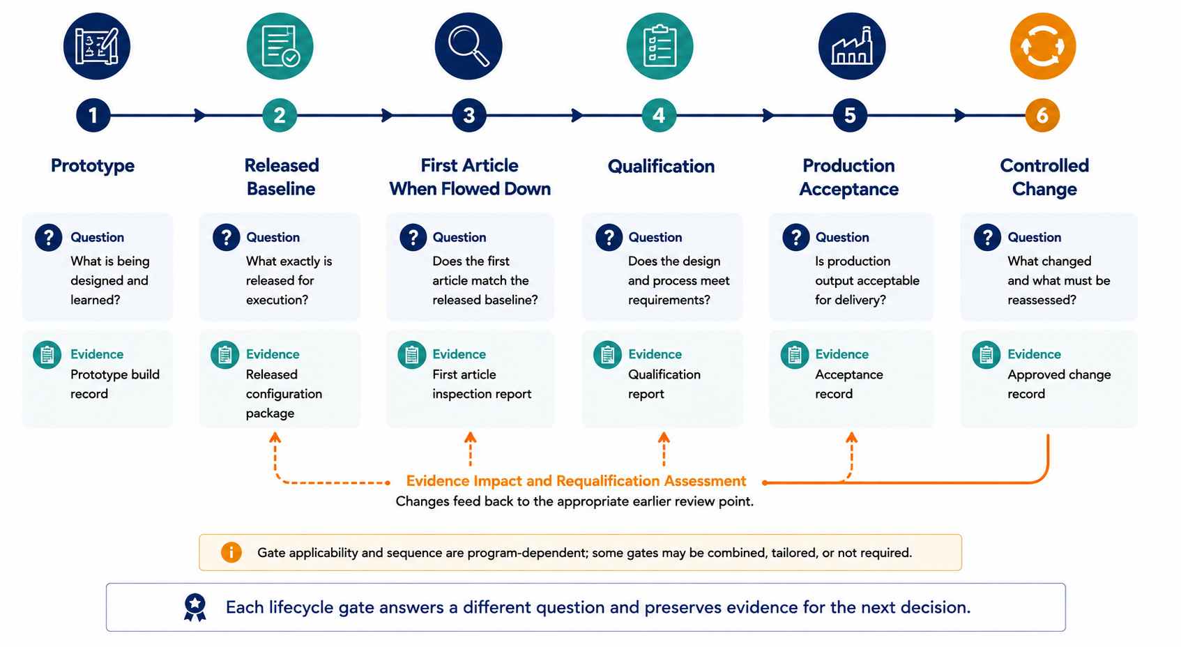
The success of a prototype is evidenced by the functionality, assembly feasibility, and compatibility of the component and not by FAI, qualification, production acceptance, or validity after change. Each lifecycle gate must have its own distinct set of questions, configuration identity, documentation, and evidence required to approve each phase.
- Prototype – Confirm Design Intent, Assembly Feasibility, and Interfaces. Document all deviations from the design.
- Released Baseline – Create approved documents that contain the design documents, BOMs, approved vendors, assembly notes, software, test limits, and document precedence for future controlled builds.
- FAI – Verify the FAI characteristics when required by the contract. As defined by the IAQG 9102 standard, it provides a consistent FAI process for aviation, space, and defense products. It does not establish environmental qualification or prove performance in the customer's intended mission environment.
- Qualification – Qualify the Representative Configuration as per an approved plan. Maintain all records of the representative configuration including identity, mounting, operating states, profiles, anomalies, test results, and approval signatures.
- Production Acceptance – All parts or assemblies must be verified against the Released Baseline and the Contractual Acceptance Plan. Qualification of an assembly does not supersede the need for Routine Inspection and Testing.
- Controlled Change – Before the introduction of a new part, material, supplier, manufacturing process, fixture, software revision, board revision, or installation assumption, determine whether it has any effects on evidence that was generated in the previous build. Establish a threshold of notification, how the technical review will occur, the approval authority, and what type of verification and requalification will need to take place prior to manufacturing the first production unit.
Alternate parts can affect mass, thermal behavior, radiation response, or electrical performance.
New processes or fixtures can affect the quality and test coverage of the product.
What Does Each Inspection or Test Actually Prove?
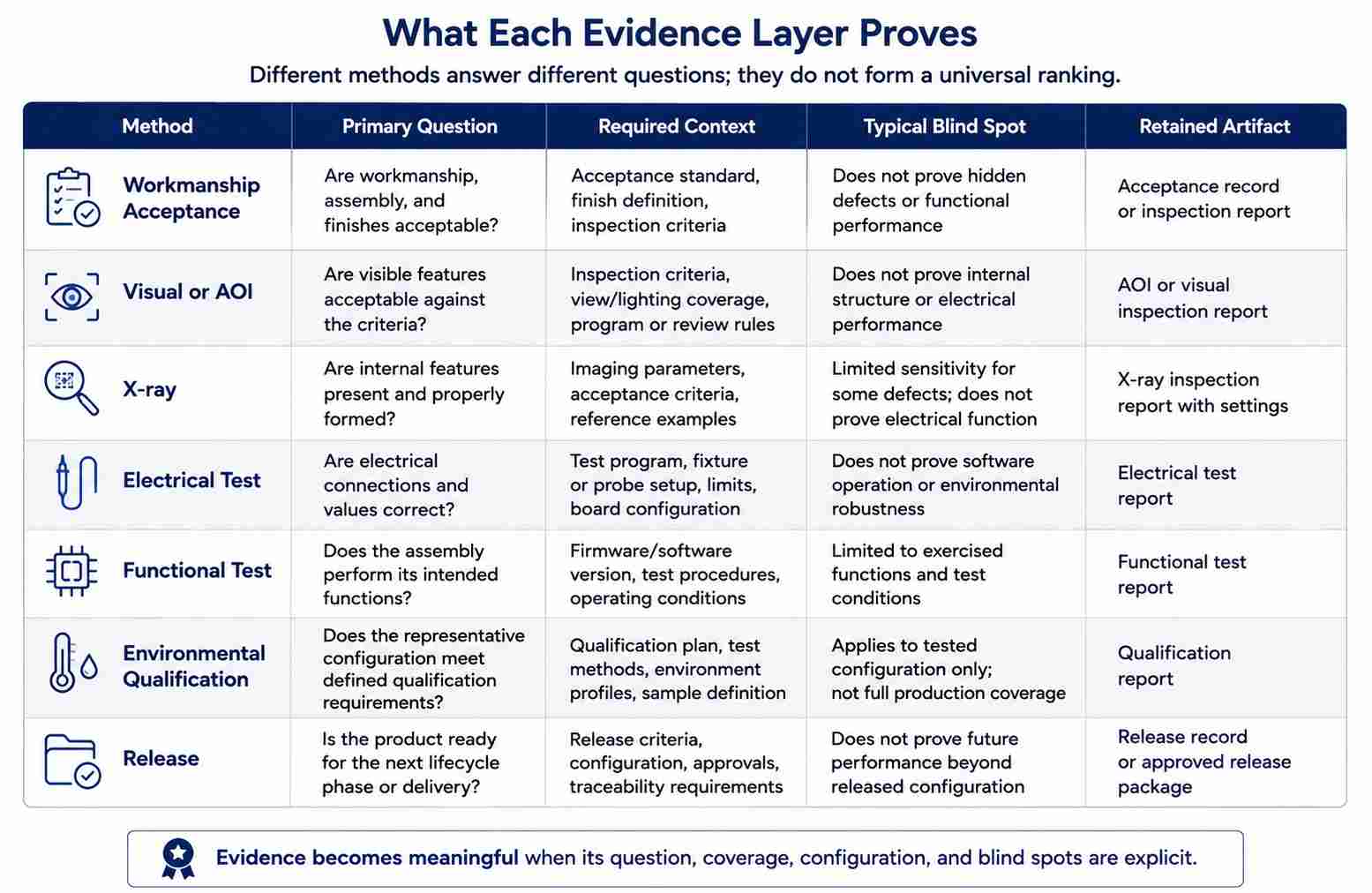
Inspection, Manufacturing Test, Functional Test, and Environmental Qualification answer different questions. The name of a method does not determine its coverage. Every result should be interpreted according to its requirements, configuration, limits, unit identification, anomalies, outcome, and approval authority.
GSFC-STD-6001A addresses area-array assembly within its stated scope and does not provide application-specific reliability qualification requirements. The traceability, coverage, and criteria for the term "AOI Passed" must be established. The coverage for "functionally tested" includes the required firmware, fixture, modes, limits, and unit identity. The coverage for "DO-160 tested" includes the categories, specimen configuration, operating state, results, and acceptance process used to assess compliance.
Where governing documents have established acceptance criteria for IPC Class 3, these criteria may apply.
Qualify the Supplier by Evidence, Not Aerospace Labels
There should not be reliance on a wall of logos.
Determine the connection of certificate scope, controlled data, manufacturing history, test coverage, genealogy, non-conformance, outsourced work, changes, and information management to the actual program requirements.
Start with eligibility and the released baseline
Confirm the site, scope, standard, and status of the certificate through the appropriate authoritative scheme.
Review the contract and compare the information with the released drawings, approved BOM sources, assembly documentation, specifications, data markings, and precedence rules.
Having a current certificate with the wrong site or scope will not support the project.
Alternatives to the baseline must be formally documented and controlled.
The person providing authorization for a specific component, material, process, or source substitution must be defined. Also preserve that decision in the as-built configuration. Otherwise, valid records may describe qualified hardware that no longer represents the authorized design.
Programs with extended service lives must also consider and define how they will handle the following:
- Obsolescence
- Last-time purchases
- Brokered materials
- Counterfeit or suspect counterfeit parts
- Alternative sources or components
Evidence of approved-source control, authenticity or traceability when required, and formal alternative approval must be documented.
A single component can pass visual or electrical testing and still be unacceptable because the source, lot, configuration, or substitution was not authorized.
Request representative process and test evidence
A binder full of certificates that cannot be traced to any specific unit's work instructions, equipment records, and test results is not an adequate form of representative evidence and is not traceable decision support. Request connected examples rather than a binder full of copies.
Pricing and lead time are greatly influenced by documentation, FAI, fixtures, qualification, lot size, constrained materials, change review, and controlled-data handling.
Usually, two quotes for the same drawing that show a 3x difference do not price the risk of the same drawing differently, but rather price different scopes of documentation, FAI, and test coverage that the RFQ never described.
Prior to submitting a request for a quote, prepare the program context, governing documents, released data, criticality, environment, tests, retention rules, change authority, and markings.
Conclusion
The useful supplier record connects released product data to approved materials, processes, as-built configuration, inspection and test coverage, decisions regarding nonconformance and changes, and the authority that accepted the resulting hardware. Material properties, process capabilities, and test methods provide value when connected to that chain and to the actual installation environment, which is the practical difference between an assembly simply using aerospace terminology and one whose hardware and evidence support a controlled program decision.
References & Sources
- 9100 Quality Management Systems – Requirements for Aviation, Space and Defense Organizations – International Aerospace Quality Group
- IAQG Certification – International Aerospace Quality Group
- 9102 First Article Inspection Requirement – International Aerospace Quality Group
- IPC-A-610J – Global Electronics Association
- Electronics Assembly Standards – Global Electronics Association
- AC 21-16G – Federal Aviation Administration
- AC 20-152A – Federal Aviation Administration
- NASA-STD-8739.6B – NASA Technical Standards System
- GSFC-STD-6001A – NASA Technical Standards System
- NASA Outgassing Database – NASA Goddard Space Flight Center
- ECSS-Q-ST-70-12C Rev.1 – European Cooperation for Space Standardization
- NIST Special Publication 800-171 Revision 3: Protecting Controlled Unclassified Information in Nonfederal Systems and Organizations – National Institute of Standards and Technology Computer Security Resource Center
- Defense Export Controls and Compliance System New Registration User Guide – Directorate of Defense Trade Controls, Bureau of Political-Military Affairs, U.S. Department of State
- P95/P25 Polyimide UL HB Prepreg and Laminate Technical Data Sheet – Isola Group