Upload BOM & Gerber

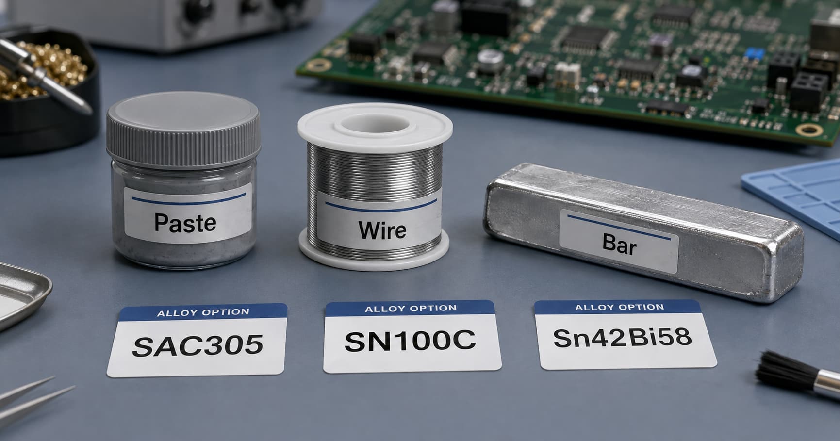
Lead-free solder is a family of fusible alloys used to join electronic conductors and components; it does not have one defined formula. For example, SAC305 nominally contains 96.5% tin, 3.0% silver, and 0.5% copper, while SN100C is a tin-copper alloy without silver but with nickel and germanium additions to the alloy matrix. The term "lead-free" does not mean that there is zero lead; it should always be associated with a known alloy specification, material declaration, or regulatory threshold for lead-free compliance. Therefore, "lead-free" is not sufficient evidence on its own to verify that the product contains 0.000% lead (zero percent) or to verify compliance for a completed assembly. A useful material description will classify four categories: alloy composition, flux system, product form, and process or application. During production use, material tracking, thermal profiling, and finished-assembly verification should occur within a controlled lead-free PCB assembly process.
- SAC305 contains nominally 96.5% tin, 3.0% silver, and 0.5% copper.
- SN100C is a specific alloy of Sn-Cu-Ni-Ge and is not an umbrella term for all Sn99.3Cu0.7 alloys.
- Paste, wire, and bar refer to product form but do not identify alloy composition.
- Select both alloy and form according to the process type, maximum thermal limits, material interfaces, flux system, expected loading, final cost, and regulatory requirements.
Contents
show
What Is Lead-Free Solder Material Made Of?
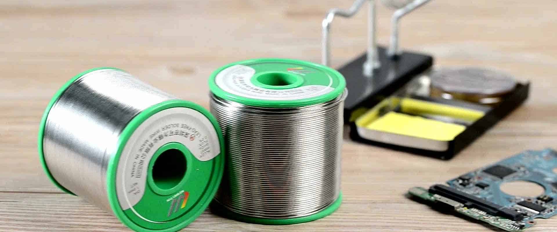
Lead-free solder typically starts with tin as the base metal, but other metals are added to create alloy systems that produce desired melting and functional properties. Silver and copper are often added to the SAC family of alloys; other formulations may include bismuth, antimony, nickel, germanium, indium, and possibly very small quantities of other metals. Not all lead-free solders include silver as an element. IPC J-STD-006 provides specifications for electronic-grade solder alloys and solid forms, including bars, ribbons, wires, and powders (IPC J-STD-006C). IPC's revision table identifies the active document versions (IPC Document Revision Table).
The nominal percentage values used in SAC and other alloys normally refer to weight unless stated otherwise. The letters used in the designation SAC305 identify the elements present—Sn, Ag, and Cu—while the numbers represent the percentages of silver (3.0%) and copper (0.5%).
The name identifies a family, not a fixed formula
Color, shine, stiffness, or melting behavior cannot identify an unknown sample. You must rely on the label, technical data, CofC, or appropriate analysis. Historical Sn-Ag-Cu family solder recommendations do not prove that an unknown material is SAC305 (NIST, Lead-Free Solder Alloys: NEMI Recommendation).
What the added elements can change
- The use of silver and copper can affect phase behavior, wetting action, intermetallic formation, mechanical response, and the cost of solder alloys used in SAC systems.
- While the use of bismuth can decrease the melting point of solder alloys, alloy compatibility, contamination, secondary heating, service temperature, and mechanical loading will all need to be considered.
- While antimony is included in higher-melting tin alloys, just because an alloy has a higher melting point does not mean that it is suitable for applications that require continuous exposure to high temperatures.
- For SN100C lead-free solder alloys, nickel and germanium are very minor yet distinct additions to the alloy. The presence of these minor amounts of nickel and germanium differentiates it from generic Sn99.3Cu0.7 solder.
The terms "stronger," "more reliable," and so on require reference to a load condition, test method, material interfaces, and comparative alloys.
Alloy, Flux, Paste, Wire and Bar Are Different Things
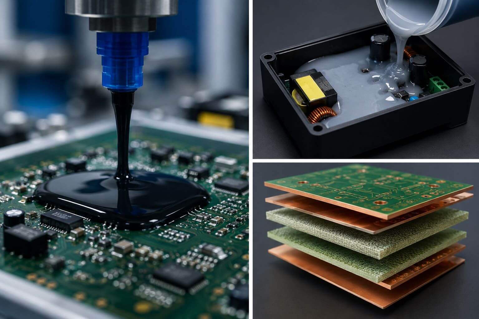
The alloy composition represents the metal itself, while the flux represents the material used to remove oxides and promote wetting on the surfaces of the materials being joined. The term "lead-free paste," however, leaves the specific alloy composition and flux system unresolved.
The combination of solder-alloy powder with paste flux creates solder paste. The requirements for solder paste are addressed by IPC J-STD-005B, separately from the solid-alloy scope of J-STD-006 (IPC J-STD-005B). The powder class, activity level, residue, storage method, and processes used with solder paste continue to be important.
Wire may be solid wire or wire filled with a flux material. Commercial solder bars are melted in pots and are commonly used for wave soldering, selective soldering, or dip soldering. Because SAC305 is available as paste, wire, and bar, the alloy name alone does not identify the product form (AIM Solder, SAC305 Lead-Free Solder Alloy).Typically, solder paste is used for SMT assembly, while solder wire is used for manual soldering and repair, and solder bars are typically used for wave or selective through-hole assembly.
What a complete solder material description looks like
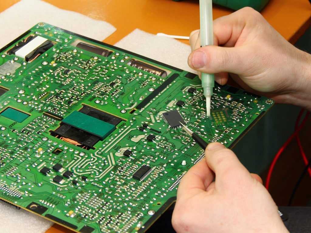
A material name becomes usable only after the alloy, form, flux or residue system, and qualified process conditions are defined.
The term "no-clean" describes a process and residue designation rather than a complete flux classification under IPC. It is not an indicator of zero residue; it implies that the remaining residue must meet the assembly's electrical, cleaning, coating, and environmental requirements.
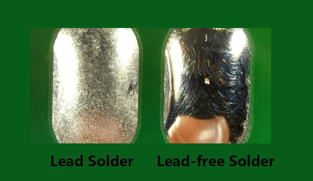
Why joint appearance does not identify the alloy or prove quality
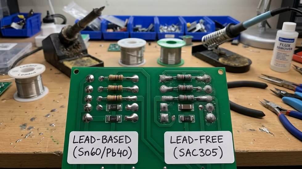
The texture of a solder joint depends on the solder alloy, how the solder solidifies, how the solder is heated, and the types of metallized surfaces being joined. Therefore, two solder joints made from the same nominal solder alloy can have different textures. The appearance of the solder joint cannot indicate which solder alloy it contains or replace the criteria used to determine whether the solder joint is acceptable.
Which Lead-Free Solder Alloys Matter Most in Electronics?
Three lead-free solder alloy groups are important to the electronics industry: SAC305, Sn99.3Cu0.7, and SN100C (Ni-Ge). Sn42Bi58 and Sn95Sb5 represent lower- and higher-temperature solder options.Nominal composition and phase-change temperature are just the first steps in determining an alloy's suitability for a process. The alloy properties are provided by AIM, Indium, and Nihon Superior (Indium Corporation, Solder Alloys).
Nominal alloy properties are not process settings or automatic material approvals. When determining what to purchase, you should follow the supplier specifications and lot documentation. However, the way you use those materials is determined during the assembly qualification process.
Melting Point Is Not a Soldering Temperature Setting
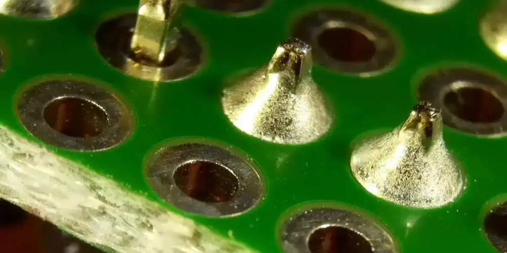
The melting point gives you an indication of when solder will start melting and when it finishes melting. However, SAC305's 217 to 220°C range is based on alloy phase behavior, not the soldering-iron setpoint, reflow peak, or solder-pot temperature.
A eutectic alloy changes between solid and liquid at one temperature. A non-eutectic alloy has a solidus, where melting begins, and a liquidus, where the material becomes fully liquid. The interval between them is the pasty or melting range. These terms describe alloy phase behavior, not the complete assembly joining process.Actual process parameters will vary based on heat-transfer ability, solder-tip or nozzle design, thermal mass of the component being soldered, size of the copper area, size and design of the circuit board, amount and quality of the flux, length of heating time, and the qualified processing window.
The setpoint is one of many parameters that control the transfer of heat into a solder joint. The other parameters include contact of the solder tip with the surface to be soldered, solder-tip design, power recovery of the soldering equipment, and preheating of the components. Excess temperature can exhaust the flux or damage components, pads, finishes, and laminate.
How Do You Choose a Lead-Free Solder Material?
Choosing a soldering material should be done with consideration for both the physical form and the soldering technique used. A comparison of thermal limits, interfaces, anticipated loads, type of flux, residual flux, total costs, and requirements will permit you to specify a soldering material and a qualification plan.
Identify the required form and process context
Identify what type of soldering material you need: SMT paste, bar for wave or selective soldering, or wire for manual soldering and rework. Then decide whether your work is for a new assembly, a previously qualified process, or a repair. Just because one alloy exists in different forms does not mean that the same specification applies to each form.
Identify mixed-alloy conditions as early as possible. Existing solder, repair wire, BGA balls, component terminations, finishes, or coatings can introduce numerous types of metal into a single joint. Successfully melting the joint does not mean that it meets any specific requirement for microstructure, process margin, or reliability.
Define the thermal and material boundaries
Identify each interface, such as PCB finish, component termination, existing solder, or coating or plating that reaches the solder joint. Record the component limits, board construction, copper distribution, joint thermal mass, and any thermal exposure that will occur after soldering.Maintain a record of the actual finish material type, e.g., OSP, ENIG, immersion silver, or immersion tin; do not merely write "compatible."
For soldering materials with low melting points, treat the melting point as part of the thermal budget used during the soldering process; for soldering materials with high melting points, treat it as an additional process requirement. Compare phase data after establishing the thermal and physical parameters for the process.
Match the flux system and residue requirements
There are similarities (e.g., oxidation, wetting, electrical sensitivity, residue limits, cleaning expectations, storage, and process), but since flux-system data are compiled through different laboratory and manufacturing methods, it is essential to validate compatibility, as a suitable alloy can still fail due to a conflict with the individual flux system.
Validate the candidate against project requirements
Validation should describe the anticipated loading of the assembly in addition to using the term "reliability." The type of evidence used to validate the alloy may include, but is not limited to, thermal cycling, drop or vibration loading, service temperature, humidity with electrical bias, repeated reflow, and rework exposure.
- The physical and material compatibility of the alloy and assembly interface.
- Stability of the assembly process within defined product parameters.
- Anticipated loading on the assembly interface during actual service conditions and for associated materials, i.e., the chemistry of finishes and terminations, solder-residue electrical conductivity risk, copper dissolution, multiple heating events, and sensitivity to rework.
In addition to the price of the alloy, the overall project cost should include formulation fees, dross produced, copper dissolution during soldering, maintenance of the solder pot, storage, maintenance of a stable assembly manufacturing process, quality inspection and rework, and qualification of the candidate. An alloy that has a lower raw-metal cost does not guarantee lower finished-process costs.
Four common material-selection scenarios
Standard SMT assemblies—SAC305 is a common starting candidate because of its broad paste supply base and large pool of process knowledge. However, these two factors alone do not determine whether the alloy will pass for the intended assembly. Fine-pitch printing will require the alloy powder class and stencil aperture and paste-release characteristics to be tailored to each other based on the pitch and substrate aperture dimensions used to assemble the circuit board. BGA and QFN packages require consideration of the thermal profile used to build these assemblies, as well as voiding, warpage, drop testing, and thermal-cycling performance. The flux and residue system must also meet the requirements for cleaning, high-impedance circuitry, conformal coating, or underfill. A typical failure chain would begin with an under-profiled reflow soak on a BGA. The volatile components from trapped flux beneath the ball array cause voiding to exceed the accepted limit. Although the board passes initial X-ray inspection, the crack path through the enlarged voids may not appear until it undergoes drop testing or thermal-cycle testing.
Consider total process costs for SAC305, generic Sn99.3Cu0.7, and SN100C instead of just raw-alloy prices. The lower silver content should lower metal costs, but this may not be reflected in the overall savings when considering dross generation, copper dissolution, hole fill, bridging, pot analysis, equipment compatibility, and reworkability. Continually evaluate the solder-pot composition, as copper dissolved in the solder and replenishment practices can cause the pot composition to move out of specification for the alloy used (i.e., Nihon Superior, SN100C). Unmonitored replenishment practices lead to excess copper in the pot, resulting in lower wetting speeds and insufficient hole fill on high-thermal-mass multilayer PCBs; this defect may be missed during visual inspection and identified only during X-ray review or cross-section inspection.
When the main priority for assembling an electronic product is to reduce component and PCB heat exposure, Sn42Bi58 may be suitable for low-temperature assembly applications. The 138°C eutectic temperature is published as material data for the alloy but should not be interpreted as defining the full reflow profile. Later rework, reflow, and environmental service exposures must be verified so that the temperature does not approach 138°C, and legacy solder or lead-bearing finish materials must be identified before use, as lead and bismuth can react and form a lower-melting brittle phase, altering the joint properties. When a Sn42Bi58 solder joint is reworked with residual Sn63Pb37 solder at the interface, a ternary phase may form. Although the completed joint may pass continuity testing when assembled, it may fail under thermal cycling or drop testing once the embrittled region is subjected to sufficient stress. Confirm the joint with cross-sectional review at the interface plus thermal-cycle testing across the expected service range, not continuity or visual inspection alone. (Reference: AIM Solder, Bismuth in Solder Alloys.)
When soldering manually or reworking, consider the alloy composition, solder-wire diameter, required flux type, residue requirements, and the material of the existing solder joint. A melting value of 217°C or 227°C does not determine the temperature at which to set the soldering iron. Several factors control the delivery of heat, including tip size and contact area, the thermal-recovery capability of the iron, joint mass, and dwell time at a given temperature. Excessive temperature can deplete flux, accelerate tip oxidation, or damage pads and components. When a soldering-iron tip is improperly sized for the thermal requirements of the joint (too small), the soldering operation will require a much longer contact time with the board to reach the desired wetting temperature; this in turn causes depletion of the flux before the solder fully wets. The result is a dull, disturbed-looking joint that clears visual inspection but has incomplete wetting at cross-section. When performing mixed-alloy rework, always document the original solder, component finish or BGA balls, and added wire before qualification. (Reference: PACE Worldwide, Lead-Free Solder and Your Equipment; HAKKO, Lead-Free Soldering.)
Does a Lead-Free Alloy Label Prove RoHS Compliance?
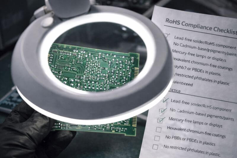
No, applying a lead-free alloy label to a product does not constitute proof of RoHS compliance. The designation of a homogeneous material's lead-free alloy, the limit established under RoHS for lead as a restricted substance, exemptions applicable to homogeneous materials, and compliance of finished products are all separate and determined individually.As stated in the EU RoHS consolidated text, the lead limit for each homogeneous material is 0.1% by weight unless an exemption applies (EUR-Lex, Directive 2011/65/EU Consolidated Text).
Solder labels do not provide compliance information for every component, finish, coating, plastic, or other homogeneous material that is part of a finished assembly. Additionally, compliance is dependent not only upon the solder alloy but also upon customer requirements, applicable exemptions, and supporting documentation.
Safety note: Lead-free solder does not mean that all soldering materials used in manufacturing are safe and non-toxic. Fumes produced by rosin-based fluxes present a potential respiratory risk, and leaded or unknown materials may require separate exposure monitoring and hygiene controls. Always use source-capture systems, adequate ventilation, exposure-risk assessment, and applicable workplace procedures (HSE, Solderers; CDC/NIOSH, Understanding Your Risk for Lead Exposure).
Frequently Asked Questions
Q1. How can you tell whether unknown solder is lead free?
You can start by reading the product label, reviewing the TDS, CofC, SDS, or material declaration from your supplier. The visual appearance of the solder, joint color, and how the solder feels when melted are not guarantees that solder is lead free or contains lead. IEC 62321-3-1:2026 describes XRF as a screening method for lead and other substances in homogeneous materials. Because of factors including sample geometry, film thickness, substrate material, calibration, detection limits, and measurement uncertainty, you may need to use an appropriate confirmatory laboratory analytical method.
Q2. Does a dull lead-free solder joint mean it is defective?
No. Dull-looking solder joints are often caused by normal solidification or manufacturing processes. You should always assess the solder joint to determine whether it passes the applicable acceptance criteria and is consistent with the expected process characteristics; the shininess of a joint's surface does not indicate whether it is defective.
Q3. Is Tin Whisker Risk Determined by the Solder Alloy Alone?
No. The strongest association with the risk of tin whiskers is the use of pure-tin or high-tin surface finishes. However, other variables that also contribute to tin-whisker risk include material structure, stress, environment, geometry, and system design. Therefore, you should not predict tin-whisker growth solely from the solder-alloy label (NASA Goddard Tin Whisker Homepage).
Q4. Can leaded and lead-free solder be mixed?
There is no single yes-or-no rule. If you want to mix leaded and lead-free solder, you will first need to identify what solder is currently in the joint and any other materials that may enter the joint. You should cross-section the joint to check for the presence of a lower-melting lead-bismuth-tin phase at the interface and conduct thermal-cycle or mechanical-shock testing of the mixed solder joint before placing it into service. While mixed solder joints may flow normally and look acceptable during assembly, a brittle phase may still be present in the joint.
Q5. Is Sn99.3Cu0.7 the same as SN100C?
No. Sn99.3Cu0.7 denotes a composition comprising 99.3% tin and 0.7% copper. However, SN100C designates a specific alloying system of 99.3% Sn, 0.7% Cu, 0.05% Ni, and Ge. While both alloys are characterized by a melting temperature of 227°C, the temperature alone does not make one alloy equivalent to the other in terms of alloy identity, oxidation behavior, process characteristics, or qualification evidence.
Specify the Alloy, Form, Flux and Application Together
A good lead-free solder specification will state the alloy used, product form, flux or residue requirements, material interfaces, thermal boundaries, and acceptance criteria. For example: “SAC305 Type 4 no-clean solder paste qualified for the specified surface finish, termination set, soldering process, thermal profile, residue limits, and loads.”
References & Sources
- IPC Document Revision Table – IPC
- IPC J-STD-006C Requirements for Electronic Grade Solder Alloys and Fluxed and Non-Fluxed Solid Solders – IPC
- IPC J-STD-005B Requirements for Soldering Pastes – IPC
- SAC305 Lead-Free Solder Alloy – AIM Solder
- Solder Alloys – Indium Corporation
- MicroDispense Solder Paste Series PDS – Indium Corporation
- SN100C – Nihon Superior
- Lead-free Solder Alloys: NEMI Recommendation – NIST
- Directive 2011/65/EU Consolidated Text – EUR-Lex
- IEC 62321-3-1:2026 – IEC
- Solderers – UK Health and Safety Executive
- Understanding Your Risk for Lead Exposure – CDC/NIOSH
- NASA Goddard Tin Whisker Homepage – NASA NEPP
- Bismuth in Solder Alloys: From Bulk Constituent in Low Temp to Performance Enhancer in High-Reliability – AIM Solder
- Lead Free Solder and Your Equipment – PACE Worldwide
- Lead-Free Soldering – HAKKO Corporation