Upload BOM & Gerber


FR4 is an electrical-grade thermosetting composite comprising woven glass reinforcement and a thermosetting epoxy matrix for electrical insulation and structural support. In a rigid PCB, the woven glass reinforces the dielectric; the cured epoxy binds the glass and separates the conductive layers. Copper foil applied to the FR4 laminate, along with the fabrication process, produces a complete PCB; however, FR4 laminate does not constitute a PCB by itself nor does it establish fixed electrical or thermal properties for the resulting PCB.
The FR4 designation represents a material grade and not a uniform “recipe” for FR4 material. The measured electrical and thermal properties associated with FR4 material may vary according to resin chemistry, glass type/style, resin content, curing system, fillers, copper type, and method of construction. Other PCB material families and their qualification requirements should be compared separately.
- FR4 laminates consist of a woven glass fabric reinforcement bonded with a cured epoxy matrix material.
- The numeric designation of 4 as part of the grade designation does not provide a universal definition of a glass type, temperature, resin ratio, or UL classification.
- A core laminate is a cured laminate and is usually supplied with copper foil, whereas prepreg remains capable of resin flow and final curing during the multilayer lamination process.
- Tg, Td, Dk, Df, moisture absorption, flammability, operating temperature, and thickness require supporting test results that can be traced back to a named product, test method, and construction.
Contents
show
What Is FR4 Material?
The term “FR4,” in a general sense, is used to describe an electrical-grade thermosetting laminate made from woven glass fabric and a thermosetting epoxy matrix. While FR4 does use woven glass as reinforcement, the glass also provides stiffness and dimensional support. The epoxy resin forms the continuous matrix after curing and serves to hold the composite together while also providing the electrical insulation necessary between copper features and other conductive elements.
Although the term “fiberglass” is often used to describe FR4, it is only a partial definition. Glass fabric is the reinforcement, but finished FR4 is a cured epoxy-glass composite and not raw glass fabric. In addition, copper is not an element contained in the FR4 dielectric, but rather it is a component of copper-clad laminate or the finished PCB.
The color of FR4 is not typically identified by a green finish, since the cured material typically has a pale yellow, amber, or off-white appearance. The color of a printed circuit board typically comes from the application of solder mask after the copper pattern has been fabricated.
ANSI/NEMA IM 60000-2021 covers industrial laminated thermosetting products. IPC-4101 identifies and characterizes laminate and prepreg materials used for the production of multilayer and rigid PCBs. A supplier may therefore refer to its product as FR4 and at the same time qualify the product to one or more IPC-4101 specification sheets.
What Does FR4 Mean?
The term FR indicates the flame-retardant context of FR4, whereas the number 4 indicates that it is a distinct grade of FR laminate when compared to other laminates. This number should not be interpreted to provide a definition for the composition of the material or to offer a thermal rating for the material. A description that states the number 4 is equivalent to UL 94 V-0, that it means woven glass, that it has a specific resin ratio, or that it offers a guaranteed operating temperature range creates certainty that the designation itself does not provide.

Flame retardant does not mean nonflammable. The UL 94 V-0, V-1 and V-2 classification system is designed to classify the performance of a material under controlled conditions as part of a vertical burning test. A V-0 rating describes material behavior under that test method and does not indicate that the material will never ignite, burn, char, or lose functionality when subjected to a fire situation.
UL recognition can depend on the manufacturer, product designation, tested thickness, color, and other conditions. A polymer that UL recognizes as a component is not automatically viewed as certified or listed as the final electronic product.
How Does FR4 Become Part of a PCB?
Prepreg starts as glass fabric impregnated with a resin system that can still flow and complete its cure during lamination. A core is already cured laminate and is commonly supplied with copper foil on one or both sides, whereas prepreg provides dielectric bonding between core layers and copper layers in multilayer PCB construction.

During lamination, prepregs, cores, and copper foils are subjected to controlled heat and pressure. As a result, the epoxy resin flows, fills the intended spaces, and cures to form the dielectric structure of the multilayer PCB. Copper patterns are formed through imaging and etching processes, interconnects are created by drilling and plating, and surface finishing, solder mask, marking, and profiling are performed prior to assembly.
When something is measured for thickness, the object being measured must be clearly identified. Core thickness, pressed prepreg thickness, copper-clad laminate thickness, dielectric spacing, and finished-board thickness are not interchangeable. Even though 1.6 mm is a common convention for the final thickness of a PCB, that value does not reflect a universal thickness of FR4 material.
Key FR4 Properties and How to Read Them
A property value is only useful when accompanied by its associated test method, units of measure, specimen, conditioning, direction, frequency, and construction.

Named FR4 Grades Show Why One Generic Value Is Not Enough
These examples are not a ranking, and the electrical values should not be treated as directly interchangeable because the test conditions and constructions differ.
Standard, high-Tg, and lower-loss products can all carry an FR4 designation while functioning differently. When modeling impedance or loss during operation, one should use frequency- and construction-specific properties rather than catalog shorthand. Those distinctions are further detailed in the Guide to FR4 Dielectric Constant and Construction.
Why Is FR4 Widely Used?
FR4 is commonly used because it provides a practical balance rather than the highest properties in every area. FR4 provides stiffness and dimensional support from woven glass, electrical insulation and adhesion from cured epoxy, and the ability to utilize established PCB processes for drilling, imaging, plating, lamination, and assembly.

The global supply base provides manufacturers with access to many different glass styles, resin systems, thicknesses, copper foils, and thermal classes. This availability supports prototype PCBs as well as production volumes without requiring every ordinary circuit to use a specialized substrate system.
These benefits do not mean that all grades of FR4 are equal. A general-purpose FR4 grade may be sufficient for use within an ordinary control board, but it may be inappropriate for repeated lead-free reflow, a demanding high-speed channel, a high-voltage spacing requirement, or a tightly controlled automotive environment.
Common Applications and Selection Scenarios
General-Purpose Control and Consumer Electronics
Power supplies, appliance controllers, basic interfaces, sensor hubs, and many consumer products use FR4 because their signal-loss, temperature, and mechanical requirements can often be accommodated by traditional rigid-board construction. Simply choosing a specific board thickness will not facilitate the material-selection process. Rather, the most appropriate laminate grade will depend on the requirements of the respective stack-up, soldering profile, voltage spacing, flammability record, and service environment.
For a moderate environment and established fabrication process, a named standard-Tg or mid-Tg grade may provide the required performance without the cost and processing changes of a specialized laminate.
Industrial and Automotive Control Electronics
Industrial drives, automation controls, instrumentation, and vehicle control modules also incorporate FR4 materials. However, industrial and automotive electronics applications present more demanding laminate-selection requirements because of thermal cycling, humidity, electrical bias, vibration, connector loads, board size, heavy components, and repeated reflow. Specifically, the material record should include Tg, Td, Z-axis expansion, T260/T288, moisture behavior, CAF performance where relevant, and the exact qualification required by the finished product.
As one concrete reference point, a high-Tg product such as Isola 370HR lists a Z-axis CTE of roughly 45 ppm/°C below Tg, climbing several-fold above that transition; this illustrates why plated-hole fatigue life depends on the product’s thermal cycle rather than on the Tg number alone.
High-Speed and Loss-Sensitive Signal Paths
There is a misconception that there is a “cut-off frequency” at which FR4 materials are no longer usable for high-frequency applications. The operational performance of FR4 materials for high-speed signals depends on channel length, rise time, insertion-loss budget, impedance tolerance, copper roughness, glass construction, resin content, and the measured Dk and Df values used for the channel. A short digital interconnect may remain practical at a frequency where a long backplane or RF path cannot meet its loss budget. When ordinary FR4 data is too variable or lossy, a verified lower-loss FR4 grade or a purpose-designed low-loss laminate may be required. The selection should be based on channel calculations rather than an unsupported 1 GHz cutoff.
Power Electronics and Heat-Generating Assemblies
The use of a higher Tg helps maintain the mechanical properties of the resin system during elevated-temperature processing and service. However, higher Tg does not convert FR4 into an efficient thermally conductive or heat-spreading structure. The thermal conductivity of standard glass-epoxy laminates is typically in the range of a few tenths of a watt per meter-kelvin, roughly two orders of magnitude below copper. If the heat produced by power devices is required to be transferred away from the substrate, it will need defined heat-transfer paths through copper planes, thermal vias, heat sinks, chassis contacts, or other structures. If substrate heat spreading is a critical requirement of the design, metal-core thermal structures or another verified thermal solution may be more appropriate. Tg, maximum operating temperature, and thermal conductivity should be treated as separate considerations.
How Does Thickness Affect FR4 PCB Design?
In terms of finished thickness, the decision on stack-up is based on the end-use application. There are common values of finished thickness like 0.8, 1.0, 1.2, 1.6, and 2.0 mm. Finished thickness will ultimately depend on the specifics of each application and the individual fabricator’s process. Connector fit (e.g., card-edge connectors, press-fit hardware, and some through-hole components) can only accept a defined thickness range and tolerance.
For example, if the application involves a larger board, heavy transformers, heat sinks, or significant vibration, this design approach may necessitate additional support, greater stiffness, or a different mechanical structure. Dielectric spacing affects trace impedance together with trace width, copper thickness, Dk, solder mask, and reference-plane geometry.
Very thin boards tend to deflect during the processes of printing, placement, reflow, depaneling, and connector insertion unless they are supported by an adequate support structure.
In portable products, thinner boards generally reduce the space used and the weight of the total product, provided the requirements for warpage, handling, connectors, and reliability are satisfied. Although the final thickness has been established, it is important to specify and understand individual core and pressed-prepreg dimensions so that the finished thickness is not substituted for the dielectric-spacing requirements, as substituting these two metrics may produce incorrect impedance, copper balance, or overall tolerance.
When Is FR4 Not the Best Material?
Long high-speed channels or loss-sensitive RF applications may require a more stable Dk, a lower Df, smoother copper, and controlled constructions. Actual loss budgets should be compared with purpose-built low-loss RF laminates rather than comparing FR4 to other laminates by frequency alone.
For applications that experience sustained high temperatures, severe thermal cycling, repeated high-temperature assembly, or strict plated-hole reliability, it may be advisable to use a higher-Tg, lower-CTE, higher-Td grade or another resin system. A higher Tg does not indicate that every thermal reliability requirement will be met.
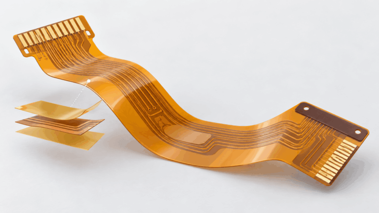
If a product will bend many times, it will need a flexible dielectric and copper system; a thinner rigid FR4 laminate will not meet the specifications for a qualified flex circuit. Similarly, when products are exposed to outdoor UV radiation, aggressive chemicals, prolonged moisture, high voltage, or unusual mechanical shock, product-specific evidence should be provided rather than generic information stating that FR4 is suitable for harsh environments.
How to Select an FR4 Grade
Despite being helpful in narrowing the search to a specific grade (for example, standard FR4, high-Tg, halogen-free, CAF-resistant, or low-loss), these are simply descriptors and do not provide a basis for selecting a product with confidence. The process for selecting an appropriate FR4 laminate consists of six steps:

- Specify the operating, assembly, electrical, mechanical, environmental, and compliance requirements for your project.
- Identify the manufacturer of the laminate and the specific product grade rather than relying on the family name alone.
- Obtain the associated IPC specification sheet, technical data sheet, UL record, or any other form of controlled qualification evidence.
- Record the test method, test frequency, test direction, conditioning, units, and specimen construction associated with each critical value.
- Relate the material data to the corresponding glass style, resin content, pressed thickness, copper type, layer stack-up, and fabrication process.
- Establish acceptance criteria and maintain the same controls on any alternate materials prior to approving their use.
Following this process will help you avoid the two most common mistakes when selecting FR4 laminates: (1) approving two FR4s based only on their designation; and (2) rejecting a suitable product based on an internet reference that does not correlate with data from the product itself.
Frequently Asked Questions
Q1. Is FR4 Naturally Green?
No, the green surface on many circuit boards is solder mask material. The laminate underneath, the cured glass-epoxy laminate to be specific, can be pale yellow, amber, off-white, or another resin-dependent color. So the color of the board does not indicate the laminate grade or prove a flammability classification.
Q2. Are G-10 and FR4 the Same?
G-10 and FR4 are both NEMA glass-epoxy laminate grades. They may share similar mechanical and electrical properties, but they are not interchangeable names. FR4 includes flame-retardant requirements that are not established by G-10. When recommending an FR4 substitution for G-10, always ensure the exact product, size, machining requirements, electrical properties, and qualification record are reviewed. Do not assume every G-10 sheet is the same as every FR4 sheet.
Q3. Does FR4 Absorb Water?
Moisture resistant is a common description, but it does not mean zero water absorption. For instance, Ventec VT-42 lists typical moisture absorption as 0.25% and maximum moisture absorption of 0.80% according to IPC-TM-650 2.6.2.1. Different grades, specimen thicknesses, conditioning methods, or exposure times can cause differences to occur; therefore, it is important to confirm a project limit against the selected product record.
Conclusion
For design requirements involving temperature, loss, moisture, flame rating, thickness and long-term reliability, the manufacturer needs to provide the exact grade, test method, construction and controlled qualification record.
References & Sources
- Industrial Laminate Group and ANSI/NEMA IM 60000-2021 – NEMA
- IPC-4101 Qualified Products List and Specification Description – IPC
- IPC-TM-650 Test Methods Manual – IPC
- Introduction to the UL 94 Vertical Burning Test – UL Solutions
- Yellow Card Plastics Recognition Program – UL Solutions
- Component Recognition and Classification – UL Solutions
- VT-42 Laminate and Prepreg Data Sheet – Ventec International Group
- VT-47 Laminate and Prepreg Data Sheet – Ventec International Group
- High Performance Laminate and Prepreg Product Catalog – Isola Group
- FR408HR Laminate and Prepreg – Isola Group
- FR-4 Material Specification Data Sheet – Atlas Fibre
- FR4: Printed Circuit Board (PCB) Material Explained – RAPID DIRECT