Upload BOM & Gerber

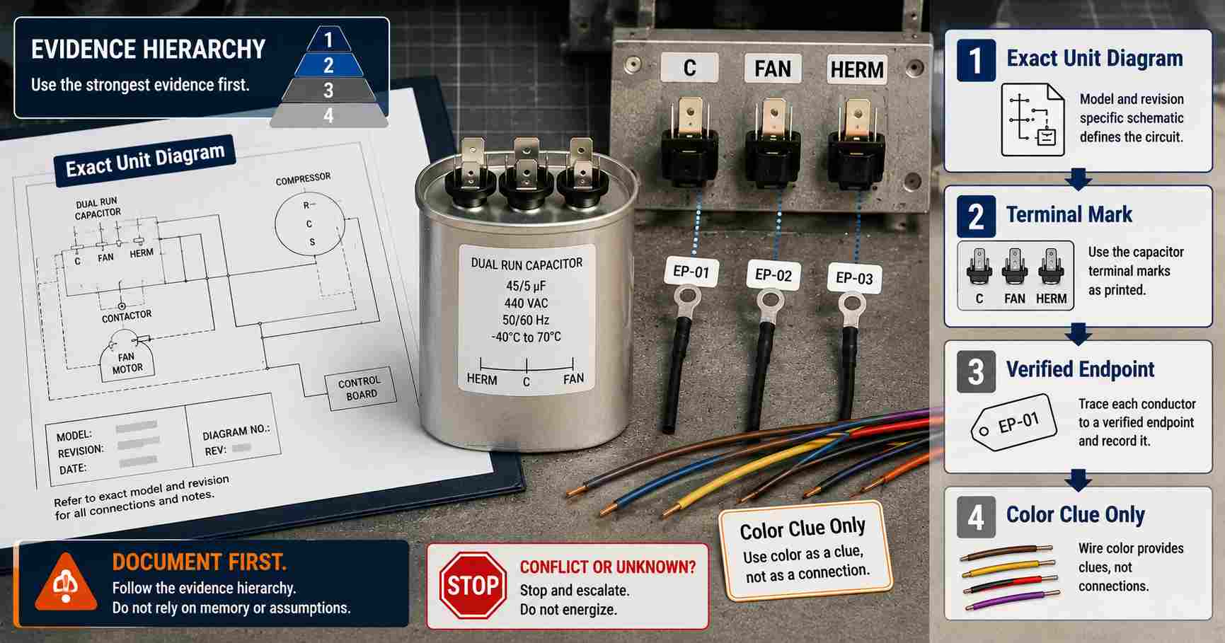
Do not use wire color alone to verify AC capacitor wiring for an A/C unit. Verify it with the exact unit schematic and installed topology, legible terminal markings, traced endpoints, replacement documentation, and matching revisions of the components.
A discrepancy indicates that the electrical circuit is not yet ready to receive power.
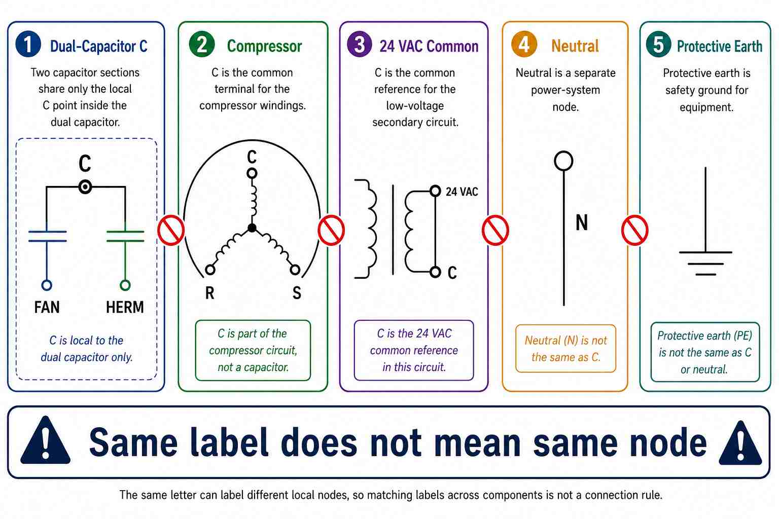
Also, the letter "C" has different meanings depending on the context. Examples: The letter "C" could designate a common point within a dual-run capacitor, a compressor winding terminal, or a low-voltage common between an A/C unit's components. Protective earth is not the same as common. Therefore, matching letters on the above-mentioned components does not indicate that you should connect those components together electrically.
Establish an electrical safety boundary before opening HVAC equipment. Opening HVAC equipment can expose personnel to potentially lethal line voltage and stored energy. OSHA requires exposed live parts to be de-energized except under limited conditions, and a qualified person must verify with test equipment (OSHA 29 CFR 1910.333) that the electrical energy source has been de-energized. Therefore, you cannot assume that simply opening a disconnect or obtaining a non-contact indication means that the electrical energy source has been completely removed. Access to HVAC equipment must follow the applicable service manual and appropriate work-control procedures. If you cannot access a unit safely or if there is any uncertainty regarding the energy state of the unit, stop.
Contents
show
AC Capacitor Wiring Starts With the Unit Diagram
The original unit wiring diagram for your specific model and revision is the controlling reference for AC capacitor terminal mapping. Daikin's DZ18TC documentation clearly separates the dual capacitor's H, F, and C points from compressor C/R/S, 24 VAC common, and equipment ground. It also directs readers to the unit wiring diagram because wiring may change.
Rank the evidence by decision value. Many weak pieces of evidence cannot outweigh the reliability of a current model-specific schematic.
Capacitors are represented on diagrams with schematic symbols. While you can find the capacitor in the diagrams, the symbol does not provide the information needed to define the connection of a wire unless you also have a reference designator, terminal mark, and endpoint.
Any reviewer with proper qualifications should be able to trace the same wiring map back to the same model, revision, labels, and endpoints. If your conclusion relies only on your ability to remember a color code, then it is not substantiated.
When interpreting a wiring diagram, always keep the terminal names associated with the component separate from the nodes that they connect to. To identify where the capacitor connects, start from the capacitor's C/FAN/HERM terminal group, continue to the named motor or compressor terminal, and follow through to any contactor or control connection that may be present. Just because multiple components share the same letters does not mean that they represent a common electrical node. To establish that a lead is properly assigned, the reference designator, terminal mark, and continuous path on the schematic must all agree.
Which Capacitor Configuration Is in the Unit?
Before attempting to interpret any lead, identify what type of topology is installed. A run capacitor with two terminals represents a completely different terminal model from a dual-run capacitor with three groups. Two separate run capacitors are independent components, while a motor replacement might change the count of visible wires.
Run capacitors are integral to the applicable motor circuit under normal operating conditions and support the phase relationship as defined by the motor design. Start capacitors perform a different function by providing temporary starting assistance and are ultimately removed or switched out through the starting circuit. The dual-run capacitor does not combine the start and run functions but packages two run-capacitor sections into one package, typically for the compressor section and the condenser fan section (Compressor Motor Starting vs. Run Capacitor Guide).
- One Run Capacitor: This should be labeled as an AC-duty section and have two terminal groups, whose connections are determined by the label of the run capacitor, the motor drawing, and the schematic of the unit.
- Dual Run Capacitor: It has two sections but shares one "C" terminal group and has a separate terminal group for the compressor motor (HERM) and the condenser fan motor (FAN).
- Separate Run Capacitors: These are two independent sections: the condenser fan motor section and the compressor motor section, each of which has an associated load as described in the documentation.
- Start Circuit: A start capacitor with a relay or equivalent switching arrangement, with instructions specific to that device.
- Replacement Motor Arrangements: Lead schemes for replacement motors must match the documentation for both the new motor and the unit.
Refer to Regal Beloit's Life-Line installation guide for the HVAC system schematic, and follow the installation instructions provided by the manufacturers of any additional devices installed (installation guide for Life-Line Capacitor Kits).
Never assume that all motors have the same external capacitor scheme; they may differ depending on the manufacturer and type of motor. For example, PSC motors typically operate with a run capacitor, while ECM motors operate with electronic controls and therefore may be wired differently externally; identify the motor architecture and refer to its documentation before interpreting a missing or added capacitor (Regal Beloit's PSC Motors vs. ECM Motors).
Never transfer the color code for the removed motor to the replacement motor; the replacement motor may have a different lead count or dedicated capacitor connections that reflect a different internal arrangement. If it cannot be verified that the new motor diagram and the unit topology match, stop and check the documentation for that specific motor.
A run capacitor is classified as AC-duty, and therefore, the marks C, FAN, and HERM are not for the identification of positive or negative polarity. The identification of polarity for a polarized electronic component is covered in the capacitor polarity reference section.
What Do C, FAN, and HERM Identify?
A dual-run topology represents two capacitor sections with one shared connection point, with the letter "C" representing the shared point. "FAN" represents the section for a fan motor, and "HERM" represents the section connected to a hermetic compressor. These letters designate functional roles of the capacitor sections; they do not imply any wire color or create a universal guide to contactor connections.
The label "45/5 µF 440 VAC" identifies one dual-run capacitor that contains two capacitance sections. In typical dual-run configurations found in HVAC systems, the larger-value capacitor section is connected to the compressor while the smaller capacitor section is typically connected to the fan; the printed numbers indicate which capacitor section each value corresponds to, not the wire color or destination points, so the motor and unit documentation dictate the connection points (Specap motor capacitor guide).
HVAC School provides an example of how the same letter can represent different local nodes; simply because "C" has different local terminal designations does not mean that the labels represent the same electrical node. This includes compressor "C" and low-voltage common "C" (C Stands for Common Mistake). The Daikin schematic displays these nodes in different areas of the diagram and uses a separate path for equipment ground.
When interpreting the capacitor terminals, always read capacitor "C" as a component-local label first; it does not necessarily represent compressor "C," neutral, 24 VAC common, or protective earth. Therefore, follow the specific schematic to determine whether two labeled terminals are connected to the same electrical node in that particular schematic.
Although multiple tabs in one group labeled "C" may be internally common within the capacitor, their number does not dictate any external circuit connections. The label and the drawing control where those terminal wires terminate.
Why Does Wire Color Fail as a Terminal Rule?
Colors only identify conductors when they are part of a specific documented harness. Any changes made to the harness, including field splices, repairs, faded insulation, replacement harnesses, or aftermarket motors, could invalidate the association with the conductor color. The color of conductors, including familiar brown, yellow, red, black, blue, or striped leads, should not be confused with their terminal location outside an appropriate electrical schematic. The colors used to identify conductors should only be used as tools to track the conductor on a drawing or assembly; they cannot be used to infer what the conductor will connect to at an unknown location.
If there are conflicts between wire color, the schematic, a legible terminal label, and a verified connection, the color should be considered failed evidence.
If an electrical schematic does not match the actual installation of the motor, either because the motor does not match the BOM or because a service change is not documented in the drawings, the identity and revision of the installed motor must be resolved first.
Record the Circuit Before Any Lead Moves
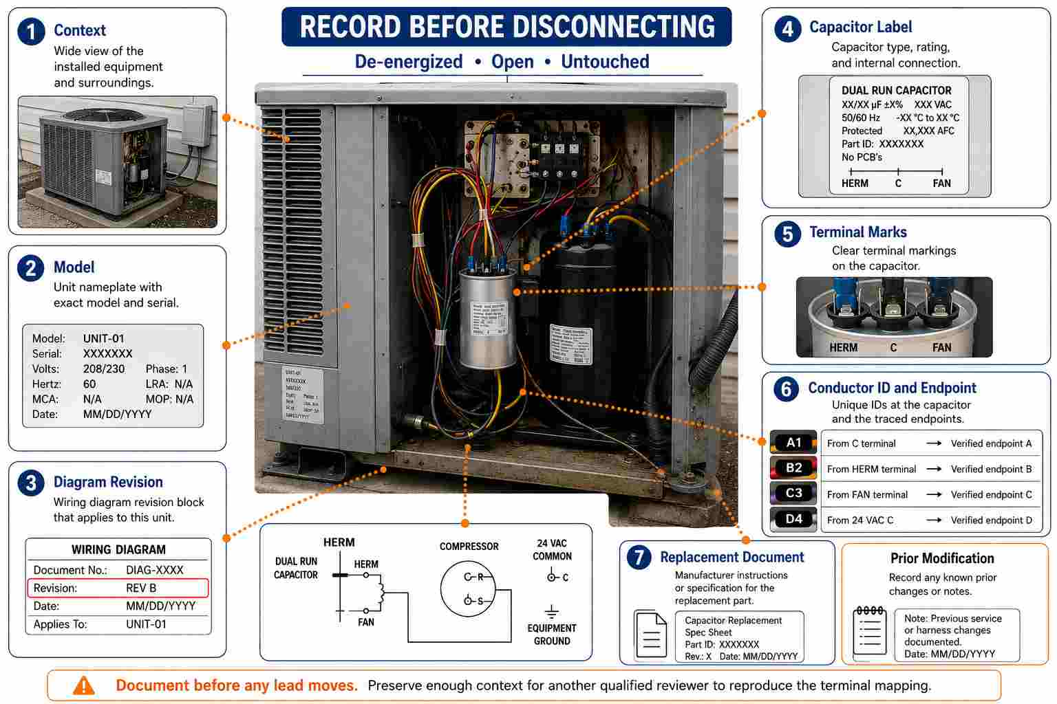
Before any conductor is disconnected from the circuit, it is essential to create an accurate recoverable record of the electrical connections to preserve the original evidence. Examples from the AMRAD Turbo200X instruct installers to record the fan, common, and compressor connections before beginning, and these examples also demonstrate that common conductors can be connected in different arrangements. A full capture requires access under the applicable safe-work procedures. A complete record of the equipment consists of:
- A photograph of the complete equipment context.
- A description of the model, nameplate, and wiring-diagram revision.
- A complete photograph of the capacitor label and legible terminals.
- An assigned unique temporary identifier for each conductor in the record.
- The verified endpoint of each conductor and a description of any splices or added devices.
- A record of the replacement capacitor and motor documentation, which should be stored with the photographs.
- Information on any prior repairs, sections of the harness changed, heat damage, or missing labels.
A photograph will provide context for the information recorded, but it does not guarantee that the previous connection was correct. If there is a conflict between the installed state and the approved documents, the conflict should be recorded. Rusted marks, cropped views, or unknown alterations prevent reliable conclusions from being made.
Does the Replacement Match Every Required Attribute?
The Specap guidelines state that a run-capacitor replacement must match the required microfarad value and use an equal or higher voltage rating.
Copeland clearly identifies run-capacitor value assignments for specific compressors, such as 30 µF/370 V and 35 µF/370 V (Copeland's product specifications). The above information represents specific models only; these cannot be viewed as generic recommendations. In transitioning from two separate capacitors to a dual capacitor, both capacitor values must remain intact, including shared-node topology, duty, voltage class, terminal connections, mounting configuration, and documentation.
When Must the Wiring Reconstruction Stop?
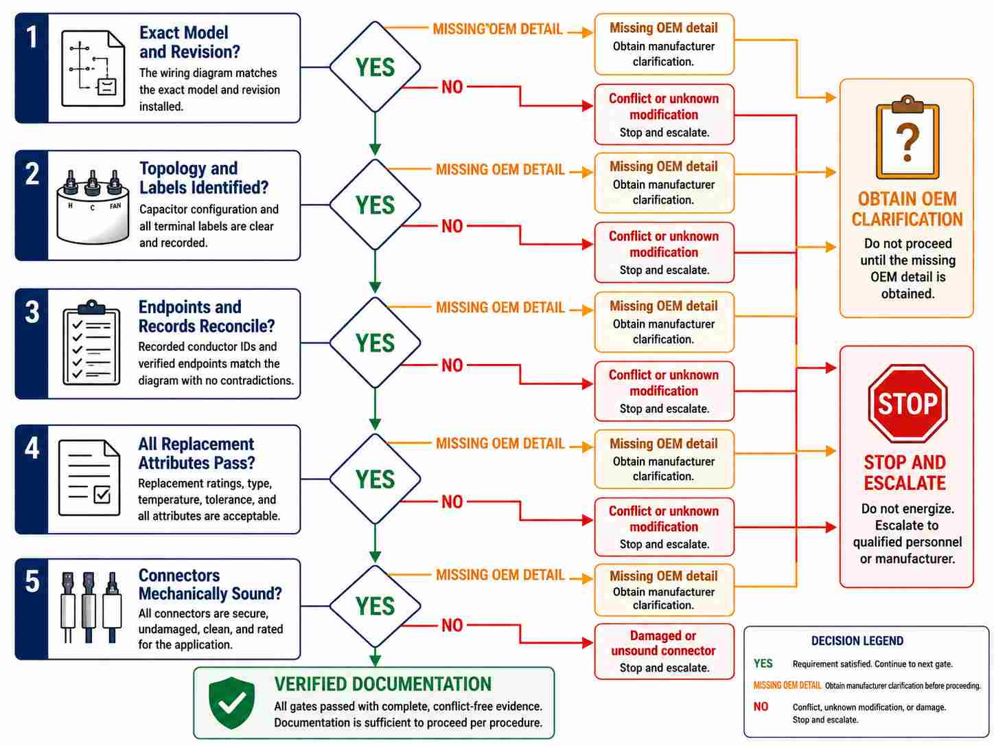
You must cease any further wiring reconstruction when the required evidence cannot be established without an assumption. Missing or deteriorated label data, a diagram revision that cannot be matched to the equipment, endpoints that remain unresolved, undocumented modifications, mismatching component ratings, and a connector that has been exposed to extreme heat all require additional follow-up and review by qualified professionals before further actions are taken.
Use the steps in order:
- Does the exact diagram match the equipment model and revision?
- Are the topology and terminal labels identifiable?
- Do the recorded conductors and verified endpoints reconcile with that diagram?
- Does every replacement component meet the specifications that appear within the documentation?
- Are all mechanical and electrical connections secure and free from corrosion or heat damage?
If any individual OEM detail is missing, it must be clarified. Any contradiction results in stopping and escalation; trial power-up is never an acceptable solution.
Terminal identity and connection integrity are separate decisions. A loose, corroded, or heat-damaged connector may create failure symptoms in an electrical circuit, but its condition cannot confirm that the terminal has been properly identified as C, FAN, or HERM until the identity of that node has been verified independently. Only after that verification is complete should you replace or repair the identified condition.
Symptoms such as humming, non-start, a stationary fan, compressor overheating, tripping, or visible damage can coexist with miswiring; however, these symptoms cannot prove miswiring. When the compressor is running and the fan is stationary, the FAN branch, including the fan capacitor section, motor, and related connection, becomes a higher-priority check. When the fan is running and the compressor is not operational, the HERM/compressor branch becomes a higher-priority check. However, when both fail to operate, the supply, contactor, common path, controls, or multiple faults remain potential causes. Symptoms can direct the next documented check but cannot identify an unknown conductor as C, FAN, or HERM (Carrier AC fan troubleshooting; Specap motor capacitor guide).
Friedrich's warning that some motor capacitors can be damaged by shorting their terminals is valid; stored energy also remains a hazard after supply isolation. Friedrich also cautions that some motor capacitors are internally fused. Always follow the exact manufacturer's service procedure and qualified-person requirements rather than using a universal discharge shortcut.
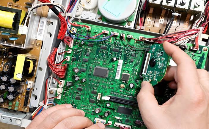
Field wiring and PCB records must share the same revision to accurately identify verified field nodes associated with the system. An OEM verified field node must remain the same node throughout the system schematic, harness drawing, connector table, control-board net names, BOM, and released manufacturing package. A change in only one of these documents can create a buildable assembly, but it may not be electrically correct. A common failure scenario: a field technician performs a repair and relabels or reroutes a harness conductor. The physical change is successful; the equipment operates correctly; however, the change is not returned to the schematic, connector table, or BOM. As a result, the next technician — or automated testing station — will trust the original documented color or label and recreate the original misconnection the first repair was intended to fix.
To maintain electrical connectivity, pin numbers, connector orientation, net names, harness colors, terminal functions, and revision identifiers must match one documented approved connectivity definition. Changes made in the field service environment must be properly controlled before being incorporated into the design record. PCB design services can support the alignment of schematic, connector, harness, and manufacturing outputs without replacing model-specific HVAC service authority.
The wiring of AC capacitors must be verified based on agreement of the following elements: wiring diagram, topology, terminal function, endpoint, rating, and revision. If there is uncertainty about any of these elements, a more confident guess based on wire color will not produce the correct conclusion; rather, the correct result is a documented stop.

References & Sources
- DZ18TC Split System Heat Pump – Daikin Comfort Technologies
- 29 CFR 1910.333 Selection and Use of Work Practices – Occupational Safety and Health Administration
- Chill Premier Service Manual – Friedrich Air Conditioning
- Examples for Wiring the Turbo200X – AMRAD Engineering
- Life-Line Capacitor Kit Installation Guide – Regal Beloit
- Motor Capacitor Troubleshooting and Replacement Guide – Specap
- 1.5 to 2 Ton ZP KA Copeland Scroll Compressors for Air Conditioning – Copeland
- C Stands for Common Mistake – HVAC School
- Motor Start vs Motor Run Capacitors: The Definitive Guide – Specap
- PSC Motors Vs. ECM Motors: A Technician's Guide – Regal Beloit
- AC Fan Not Spinning? 8 Causes & How to Fix Them – Carrier