Upload BOM & Gerber

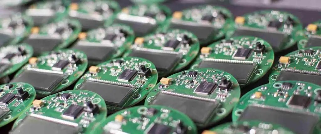
The terms "Electronic Assembly" do not refer only to PCBs and may include other assemblies, assemblies containing cable harnesses, modules, enclosed products, or complete systems. What electronic assembly really means is determined by the delivery level, revision, the work that is included, and the evidence for acceptance.
As an example, an assembled PCB is considered complete at the board level; however, it is one input into what the buyer expects as the finished product. Defining electronic assembly as only SMT leaves out many parts of the assembly process, such as cables and enclosures, as well as firmware and mechanical interfaces, and system tests. Conversely, treating electronic assembly as synonymous with all electronics manufacturing introduces additional variables: design, sourcing, logistics, and service, which are not included in the name of the physical assembly process.
Contents
show
Meaning of Electronic Assembly
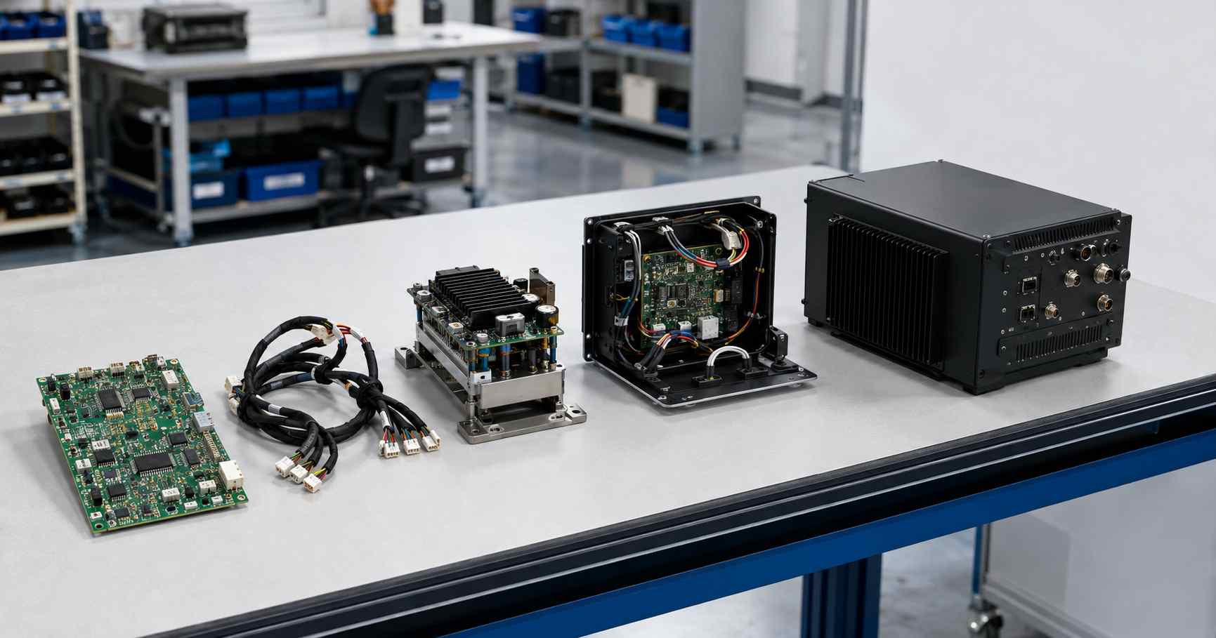
Electronic Assembly also describes controlled work to join and integrate electronic and electrical components, as well as necessary mechanical components, into a specified deliverable. You may be delivering to your customer a populated circuit board, a cable assembly, a module, an enclosed product, or a configured system.
The IEEE Technology Navigator characterizes all forms of assembly as a process of joining together components, devices, subsystems into functional products (IEEE Technology Navigator). While this is an excellent engineering definition of assembly, it should not be considered a universal definition for every job. Each job is governed by specific contract documents including the purchase order, a drawing, a statement of work, and an acceptance plan.
Retail readiness is not a requirement to begin the integration. An example would be a motor-control board that isn't mounted in a cabinet yet and a cable set that connects it to the sensors. Both of these can be completed as individual assemblies that also contribute to the overall deliverable.
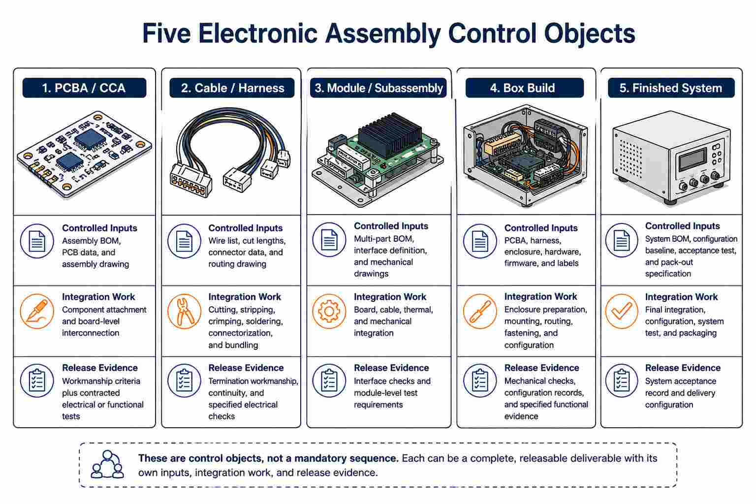
The Assembly Object Determines the Deliverable
Whether you are looking at assembly objects or making sure your assemblies meet their design intent, the physical build functions as the identifier for an assembly. Therefore, you should classify your assemblies based on the physical build of the assembly. The assembly object should not be classified by its machine, soldering route, factory department, or assembly routing.
While assembly-level definitions offer insight into the various levels of integration, they are also intended to demonstrate that a assembly-level definition does not imply a mandatory sequence for producing products or modules. In addition, while the assembly-level definition states that a module may include multiple PCBAs, it does not say anything about having to include an enclosure. Customer-supplied boards may be used to make a box build, and a completed system may omit retail packaging when the final delivery point is an industrial installation kit.
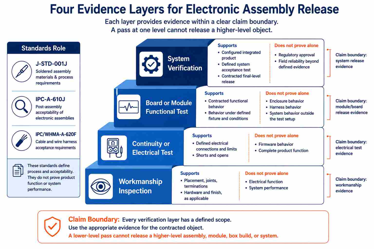
Each tier integrates lower-level parts to create additional products, but not every acceptance conclusion for lower-level parts can be projected to the upper level. All PCBA verification/acceptance data only validate the performance of the assembled PCBA with fixtures and under defined limits. They do not provide verification/acceptance for cable routing, enclosure bonding, firmware configuration, or product/system performance. Finished products are defined relative to an agreed delivery endpoint.
IPC/WHMA-A-620 covers requirements and acceptance for Cable/Wire Harness Assemblies; the Board-Level standards cover other types of assemblies. The current revision of IPC/WHMA-A-620 is recorded as IPC/WHMA-A-620F and is maintained by the GEA. For NASA's critical Cable and Harness Assembly projects, NASA-STD-8739.4A Change 4 has a specific active scope and is not a blanket requirement for commercial electronics (NASA).
Is Electronic Assembly the Same as PCB Assembly?
When stated as "PCBAs," these can be an independent deliverable or be considered as an input to a complete tested module or box build assembly.
In terms of company and industry usage, there is a distinction between electronic and electrical assembly activities. Electrical assembly often includes electrical connections between components, power distribution to the components, wiring harnesses, panels, circuit breakers, and electromechanical hardware. Conversely, electronic assembly tends to refer to circuit-level work. This should be viewed as a starting point and not as a strict legal definition. The drawings and scope of work should determine how the two assembly methods overlap.
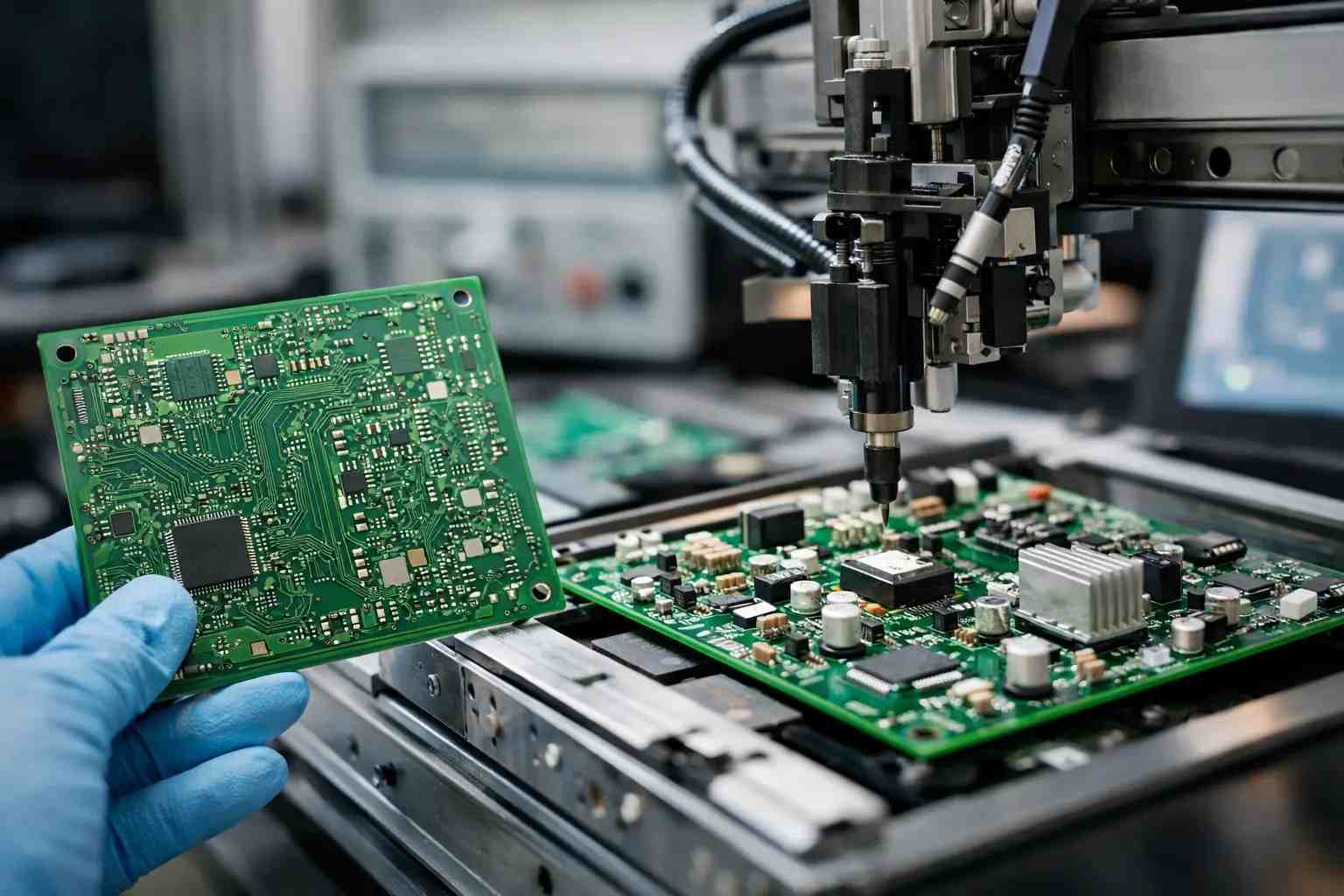
There are several different types of PCB assembly processes. SMT, through-hole technology, mixed assembly (both SMT and through-hole), and BGA-specific placement, reflow, and inspection requirements are examples of processes or package considerations specific to the board assembly level. These board-level processes do not sit alongside a cable harness or finished system as equivalent product levels. A complete overview of PCB Assembly will allow readers who need to understand board transformation to follow the entire process, while CCA and PCBA terminology needs to be addressed in its own controlled-document context. A high-level overview of surface mount technology describes the method of installation without providing a complete taxonomy of the entire assembly process.
A commercial PCB assembly quote may stop at tested boards in ESD packaging; an electronic assembly quote may include harnesses, enclosure integration, programming, labels, accessories, and system acceptance.
How Does the Process Change with the Assembly Object?
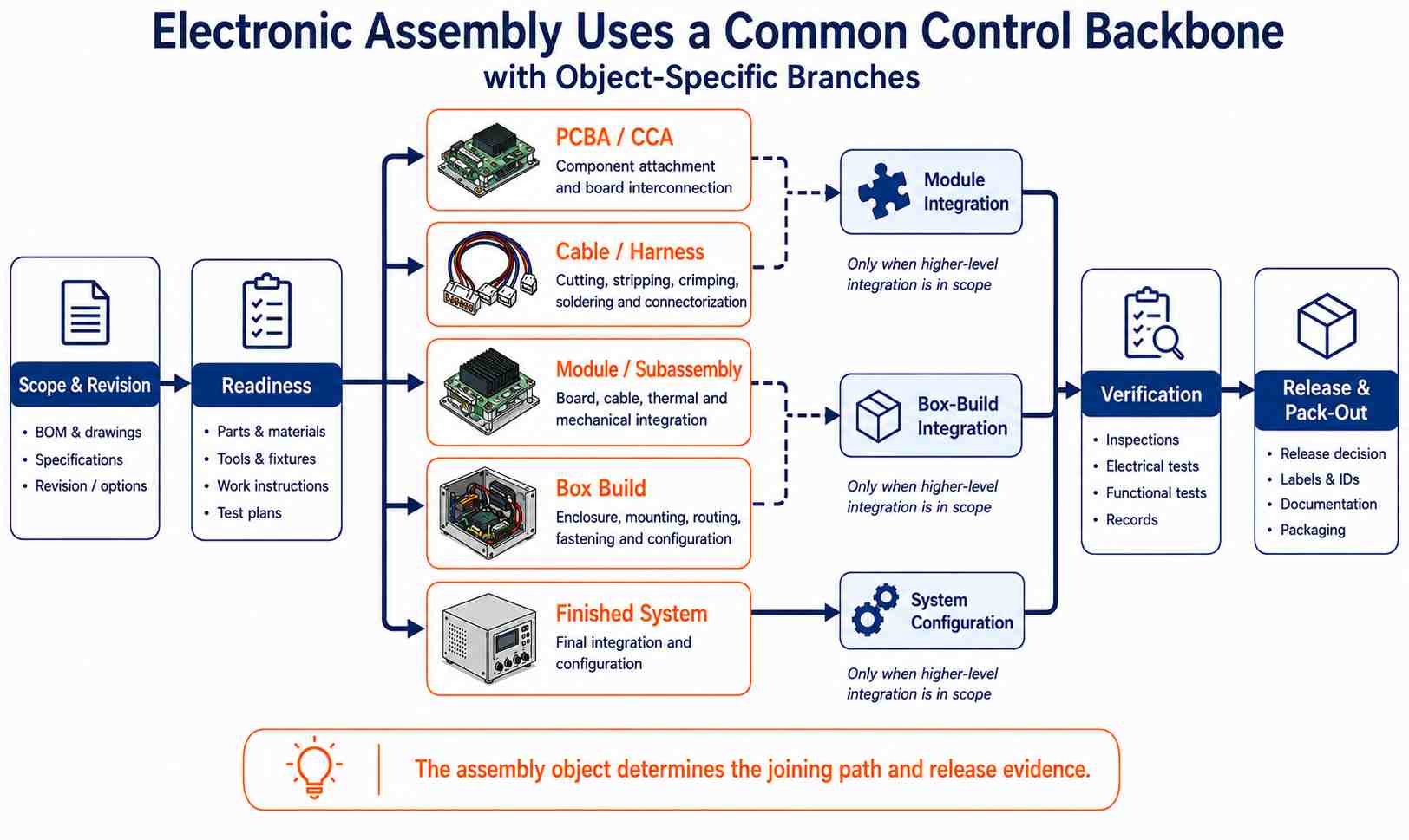
No single predetermined sequence of assembly will work equally well for PCBA, cable harnesses, box builds, and configured systems.
The process uses six controls:
- Freeze the object with the item number, revision, options, and acceptance baseline.
- Validate that the data, materials, tooling, software, fixtures, and customer-provided inputs are all ready for production.
- Perform any object-specific assembly and joining processes.
- Assemble the final assembly to the contracted level of configuration.
- Verify compliance with the inspection/test criteria and any limits that may exist.
- Release the configuration for acceptance along with its supporting documentation and pack-out.
For PCBAs, a wide range of assembly methods may be employed, including paste printing, component placement, component solder reflow, selective or wave soldering, and hand assembly. For harness assemblies, the steps may include cutting, stripping, crimping, inserting connectors, testing for pull force, and testing for continuity. For enclosure assemblies, the processes may include preparing the product, mounting the product, routing cables, applying controlled torque to fasteners, programming firmware into the product, adding labels to the product, and preparing the customer configuration.
During integration, the assemblers may discover additional assembly requirements that were not required at the lower assembly levels. For example, once an enclosure is mounted, probe access used for PCBA testing may no longer be available. Cable bend radii and strain relief become very important when determining the fixed routing of cables. Thermal interfaces will also depend on the final clamping and contact between the PCBAs and the enclosure. Firmware revisions will also depend on compatibility with the hardware revision, product option, and serial-number records.
How the Delivery Level Changes the Work
Without providing any specifications about the level of service to be delivered, you can receive two different quotes – one as a tested PCB assembly (PCBA), and the other as a fully integrated enclosure build with wiring harnesses and firmware configuration; both suppliers in these cases could describe their services as "electronic assembly," and yet only one supplier will actually be quoting the fully integrated build. The mismatch may not become apparent until the quotes are compared unless the delivery level is specified in the request.
When Is Electronic Assembly Manual or Automated?
Electronic assembly typically combines manual and automated processes as opposed to separating them into two distinct process types; which method is selected depends on numerous factors, including repeatability, geometry, presentation, accessibility of the work area, process capability, change frequency, and how much evidence will be needed to demonstrate whether the particular electronic assembly has conformed to specifications.
Consistent parts and motion patterns lend themselves to automation; this includes paste printing, placement of SMDs, reflow soldering, optical inspection, preparation of wires, labeling, dispensing, programmed testing, etc.
Manual work continues to be appropriate when dexterity and flexibility in judgment are required. For example, changes in prototype designs, low-frequency builds of special options, assembly of irregularly shaped components, connector latching, routing wire harnesses, applying adhesive, doing rework, ensuring proper mechanical fit, and packing out final assemblies may not be economical to automate. When performing manual assembly, personnel must follow controlled drawings or visual guides, demonstrate ESD and workmanship discipline, be qualified to perform soldering or crimping operations where applicable, maintain good tool control, and be familiar with proper use of measurement or test equipment.
There are no universal volume thresholds; at high volume, flexible cables may still require manual routing, while low-volume products may make use of an existing placement program.
Materials Follow the Joint and Protection Task
Electronic assembly materials depend on the joint, interface, and protection assigned to the task. There is no universal shopping list that can be applied equally to a PCBA, harness, module, or box build.
Datasheet numbers should be treated only as a baseline because engineering criteria drive the complete materials selection process; the elements defined in the headers of the control columns do not directly determine how these materials will actually perform in the final application. For a thermal compound, the actual installed gap between both thermal interfaces, as well as the compression applied during assembly, must be considered when selecting this material rather than relying only on a datasheet figure. The same level of discipline must be applied in other areas: solder alloy must suit the finish type and thermal profile of the assembly, along with the reliability target and process documents. Crimp contacts must correspond with the construction and tooling used for the wire, while coatings must be compatible with the substrate, connector, test point, residue, cure conditions, and means of repair.
It is essential to identify material ownership at the time of order placement, including customer-supplied stock, assembler-sourced items, approved alternates, lot traceability, shelf-life controls, and certificates. The box-level scope of a product should also identify consumables hidden from view by the product's BOM, including tapes, tie-downs, lubricants, sealants, and packing inserts.
When the material list begins with a generic material list, it is easy to substitute or omit a number of the materials since the generic listing does not represent the function that each material serves.
What Does Each Inspection or Test Actually Release?
Only those characteristics covered by the method, limits, and acceptance criteria are released by each inspection or test.
J-STD-001J gives material and process requirements for soldered electrical and electronic assemblies, while IPC-A-610J gives acceptability requirements after the assembly process. The organization that publishes both standards considers these to be complementary documents, not replacement documents used to validate the function of the product (Global Electronics Association). Cable and wire harnesses use a different acceptance context contained in IPC/WHMA-A-620F.
The Functional Test to be performed requires a fixture revision number, software revision number, input conditions, limits, coverage, failure disposition, and retention of results. The same type of specification is applicable to AOI, ICT, Continuity Test, Hipot Test, Leak Test, Torque Test, and System Acceptance Test. Determine the specific PCB assembly tests and inspection methods to be used after defining the risk of the product and the release claim.
For the release record, the record of the item passing the inspection or testing should include the item number and revision number. If this link is not maintained, the records of valid results may be disconnected from the hardware, firmware, or configuration for which they were intended.
Freeze the Deliverable Before You Request a Quote
To accurately compare supplier quotes, all suppliers must price the same controlled deliverable. Asking if a supplier offers Electronic Assembly is more of an initial capability screen than an actual definition of an RFQ.
When requesting quotes, the following must be frozen:
- Identity of the Assembly: name, part number, revision number, variant, and the status of forecasted changes.
- Physical delivery type: PCBA, Harness, Module, Box Build, Finished System, or an explicitly defined combination.
- Controlled inputs: BOM, fabrication files, drawings, interface definitions, software, approved substitutions, and configuration files.
- Material responsibility: Customer-Supplied versus Assembler-Sourced items, alternates, traceability, and special storage controls.
- Work Included: Joining, Coating, Programming, Labeling, Calibration, Configuration, Mechanical Integration, and Rework rules.
- Acceptance Verification: Inspection methods and procedures, test fixtures, limits, sampling, pass criteria, failure handling, and retention of records.
- Traceability and Records: Serial-number linkages, Certificates, Test data, Revision status, and Signatures required upon release.
- Pack-out: Accessories, ESD or Moisture Protection, Labels, Quantities, Packaging Configuration, and Shipping state.
Each supplier's quote, Work Instructions, Test Records, and Packaging Definitions should reference a common baseline of Hardware and Revision. Totals remain incomparable if one quote represents tested PCBAs and another represents programmed box builds with harnesses and accessories, even if both are described as Electronic Assembly.
Once the Board-Level Endpoint is clear, a discussion regarding PCB assembly services can begin and focus on the appropriate tests and manufacturing package. If a Box Build is included in the request for an object, then the interfaces for the Enclosure, Internal Harness, Firmware Configuration, Labeling, and Final Assembly must be established before transitioning into Box Build and System Integration.
How to Evaluate an Electronic Assembly Supplier
Statements that are broadly defined must be verified to ensure that sufficient controls are in place for the stated capabilities, such as Box Build, Functional Testing, Traceability, and IPC Compliance.
Name the Level, Then Define the Evidence
Examples: all electronic assembly types (PCBA, Cable Harness, Module, Box Build, Finished System) may be considered valid electronic assembly deliverables; however, they are not interchangeable. Therefore, the delivery level, revision, types of work included, level of acceptance evidence, and required pack-out for release need to be defined for the delivery.
References & Sources
- Assembly – IEEE Technology Navigator
- IPC Releases J Revisions to Two Leading Standards for Electronics Assembly – Global Electronics Association
- IPC Standards Revision Table – Global Electronics Association
- NASA-STD-8739.4 Workmanship Standard for Cables, Harnesses, and Wiring – NASA