Upload BOM & Gerber

Quick Answer
- Use a value near 4 only for an early estimate.
- Match design work exactly to the laminate, frequency, method, and construction.
- For controlled impedance, use the modeling Dk that is approved by the fabricator (often referred to as Design Dk or Dk for Impedance Design).
- Do not use a value based on FR-4, 7628, or Tg170 alone.
FR4 is often referred to as having a dielectric constant (Dk) represented as a single value near 4; however, this only serves as a rough estimate. The Dk value of FR-4 varies based on laminate grade, frequency, method of testing, glass-resin construction, and the transmission line being modeled.
The FR-4 data sheet from Panasonic illustrates this issue clearly. The R-1766(GH) laminate has a typical Dk of 4.6 at 1 MHz and 4.3 at 1 GHz when using a single test setup, but the datasheet also provides a table of different Dk values for its 1080 and 7628 glass styles. None of these Dk values are incorrect; they are based on the measurement context in which they were obtained (Panasonic Industry).
Contents
show
What Is the Dielectric Constant of FR4?
FR-4 does not have a single dielectric constant value that is valid for all circuit boards. The approximate Dk value of FR-4 may be close to 4, but to produce a Dk value for publication purposes, you will need to include four qualifiers: laminate grade, frequency of measurement, method of measurement, and specimen construction. Without these qualifiers, the Dk value is only a preliminary estimate.
Dk is the measure of the permittivity of a material compared to free space, and in PCB discussions is sometimes called relative permittivity or Er. The Dk value does not indicate the quality of signal transmission. A higher Dk value does not necessarily mean cleaner or more reliable signal transmission.
Typical values for R-1766(GH) are 4.6 at 1 MHz and 4.3 at 1 GHz. To obtain these values, testing was conducted according to IPC-TM-650 2.5.5.9 with C-24/23/50 conditioning and a 32 mil specimen. These values are specific to the IPC-TM test setup and are not automatically applicable to another construction or frequency (Panasonic Industry).
While your PCB architecture is still flexible, use the generic Dk value for FR-4 until you determine the final stackup and laminate, then use the appropriate Dk values for that specific stackup. When making decisions on PCB materials, you must maintain the same laminate grade, construction, and electrical data through the PCB fabrication process.
Which FR4 Dk Belongs in Your Design Model?
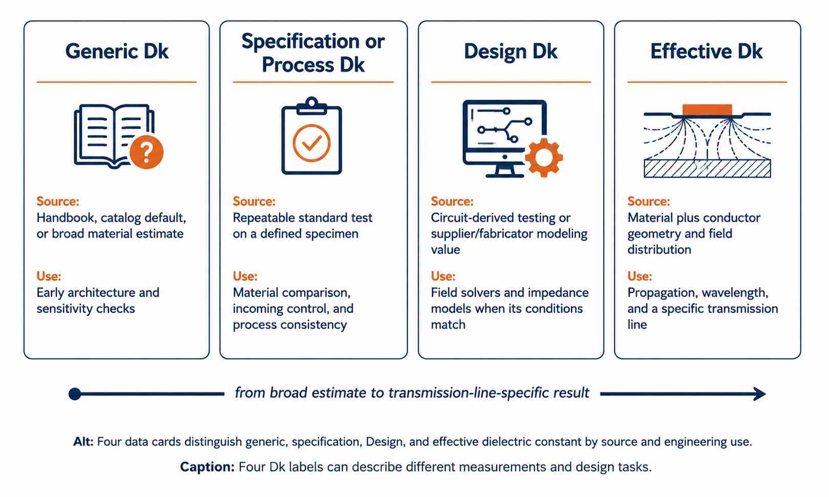
Make sure that the Dk you select is compatible with what you want to accomplish in your PCB design model. A specification Dk value can be suitable for material quality control purposes, but a modeling Dk value (commonly referred to as Design Dk or Dk for Impedance Design) can be more appropriate for the circuit model while still differing from the effective Dk for a specific trace geometry.
Rogers explains why labeling and specifications are important with its Technical Note containing data showing two laminates both labeled with a specification Dk of 10.2, but the circuit-derived Design Dk values and other test methods differ for the two laminates. The material values in Rogers' Technical Note cannot be used as if they were derived from FR-4 data. In fact, the Technical Note shows that a circuit model and a repeatable specification method can provide different numbers (Rogers Corporation).
Design Dk for Rogers is defined as a circuit-oriented value derived using the differential phase length measurement technique. This technique involves the measurement of two microstrip circuits of varying lengths to allow isolation of the phase behavior, and the resultant value is calibrated and therefore usable for CAD. Conversely, using a different published Dk as a general conversion skips that calibration process (Rogers Corporation).
Effective Dk describes an additional layer, as the microstrip field occupies both the laminate and air, whereas the stripline field is generally contained within the dielectric material. Copper thickness, solder mask, adjacent planes, and geometry also affect this distribution. Therefore, complete simulations with the correct field solver and trace geometry must be captured in high speed PCB design.
Establish what the number was measured to represent and match that purpose to the model you are creating. It would be illogical to select the closest-appearing decimal.
Consider a common mismatch of values. The component application note references generic FR-4, while the laminate datasheet references the Dk value obtained via a specification test. The fabricator's stackup references a Dk value derived via modeling. Ultimately, for final work on impedance, one would use the approved value that corresponds to the fabrication model, after confirming its grade, frequency, method, and construction. The other two values will serve as references and not as competing votes. An average would describe no specific specimen, method, or circuit.
Why Do FR4 Dk Values Change With Frequency and Construction?
The reason FR-4 Dk values change with frequency and construction is that FR-4 is a frequency-dependent composite material rather than a uniform material (Isola Group).
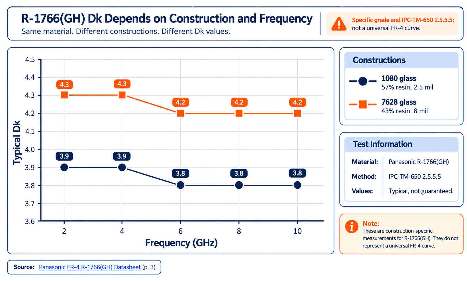
The characteristics of the laminate, including glass style, resin content, pressed thickness, measurement direction, and conditioning, contribute to the reported result. Dk varies with frequency; therefore, a low-frequency value does not necessarily have the same value when used in a GHz model, and it must be validated. It is also worth noting that temperature and moisture can affect the electrical characteristics of the laminate, and it is prudent to compare results obtained under the specific conditions relevant to the design rather than assuming that the room-temperature value does not change (Isola Group). An example of controlled comparative data on R-1766(GH) can be found using IPC-TM-650 2.5.5.5 (Panasonic).
The values listed below are typical results obtained for this material and type of construction. These values should not be considered a lookup table for all grades of FR-4 laminates.
The table's results lead to two different conclusions: Firstly, both constructions show a relatively small amount of change across the entire experimental frequency range measured, and secondly, the difference between the two constructions is greater than that within either construction. The designation label "7628" refers to glass cloth, but the listed Dk also depends on resin content and construction.
For example, Ventec makes a similar classification for its VT-42 product and lists two distinct impedance-design Dk values for the construction material identified as 106 glass with a resin content of 70%; those values are as follows: 3.55 (1 GHz) and 3.45 (10 GHz). A separate construction labeled 2116 is listed with 44% resin and values of 4.17 and 4.08 for 1 GHz and 10 GHz respectively (Ventec International Group). The numeric values are different because the grade and construction differ.
Rogers serves as an example by providing an overview of three methods of obtaining measurements: clamped stripline, split-cylinder, and circuit-based methods. Rogers outlines several sources that can introduce variation into the results, including anisotropy, copper roughness, specimen orientation, and resonance or transmission behavior (Rogers Corporation).
Read the measurement label before the decimal
The best way to determine whether two entries relate to each other appropriately is through the terminology used in the datasheet. For example, typical refers to performance observed through testing; however, guaranteed or a stated limit creates a procurement boundary. Another example is where nominal thickness differs from pressed dielectric separation. Also, a conditioning code refers to the conditions under which a specimen is prepared prior to testing. Z-axis and X-Y identify the measurement orientation, which matters when testing an anisotropic composite.
The names of each method also contribute to how researchers filter multiple sources of variation when interpreting their data. Methods such as clamped stripline, split-post dielectric resonator, free-space, ring-resonator, and differential phase-length techniques excite different fields and may examine different directions. Resonant methods typically identify discrete frequencies, while broadband transmission methods identify a different response. Although a raw laminate test may exclude copper, the copper foil profile can affect circuit extraction from the laminate. For sample information related to the number of samples tested, electrode pattern, humidity, temperature, calibration, uncertainty, and lot status, see footnotes.
The following vocabulary is helpful when evaluating the measurement context:
- As-received: measured without extra environmental conditioning.
- Clamped: held mechanically confined within a fixture.
- Resonant: derived from a frequency-specific electromagnetic resonance.
- Broadband: characterized across a continuous spectral interval.
- Anisotropic: exhibiting electrical behavior that varies with direction.
- Nominal: a named reference value that does not imply a tolerance guarantee.
- Typical: representative performance that does not guarantee a performance specification.
- Z-axis: the direction through the laminate thickness.
- X-Y plane: the plane along the panel surface.
- Pressed thickness: the dielectric thickness after lamination.
- Copper profile: the conductor-topography category affecting circuit fields.
- Conditioning: defined pre-test environmental exposure to moisture or temperature.
A good way to test whether two entries are comparable is to check if they share the same product family, specimen orientation, conditioning, fixture type, and frequency. If any of the attributes do not match, neither result is invalid; they simply raise a new question. It is up to the engineer to determine whether the differences are caused by material dispersion, anisotropy, preparation, setup, or actual formulation. Recording that hypothesis helps prevent a tidy chart from hiding incompatible experiments.
Prepreg consists of resin-impregnated reinforcement with partially cured B-staged resin, and core consists of fully cured copper-clad laminate. These records include resin content, pressed thickness, and core or prepreg construction. Impedance coupons, TDR results, and microsections provide electrical or dimensional evidence from the completed circuit board and should be regarded as verification for the model; however, this evidence does not replace the underlying electromagnetic characterization.
During the review, separate assumed values from supplier-characterized, fabricator-calculated, and production-measured values. Retain the approved laminate grade, construction, modeling Dk, frequency, source, and stackup revision so that a material or construction substitution triggers an immediate reassessment instead of unintentionally inheriting an outdated Dk.
Different methods cannot be merged into a single, smooth frequency curve that represents FR-4. There is no evidence that the different test methods established one continuous relationship; rather, the line would imply continuity that the test setups did not establish. Compare like with like or keep the datasets clearly separated from one another.
What Changes When You Use the Wrong Dk?
An incorrect Dk results in a shift between the manufactured structure and the electrical model. The result can lead to errors in predicted impedance, propagation delay, wavelength, and phase depending upon the trace geometry and effective dielectric environment; therefore, it is impossible to use a single percentage to represent all cases.
For homogeneous dielectrics, propagation velocity scales approximately with the inverse square root of Dk, while for microstrip and coplanar configurations, the effective Dk of the transmission line should be used rather than simply using the bulk laminate Dk directly.
The issue of controlling impedance is compounded by the fact that copper geometry, dielectric thickness, dielectric constant (Dk), copper thickness, and sometimes solder mask all play a role in the final result. Changing only the Dk value while holding everything else constant would provide an indication of how Dk influences the controlled impedance, but it would not recreate the actual stackup model used by the PCB manufacturer.
Delay and phase effects should be treated with the same level of attention as timing error per unit length. A small amount of timing error can accumulate along a long signal path or from mismatched pairs, causing problems in phase-sensitive networks. The best approach to correcting these issues is to ensure that the simulation input aligns with the laminate and stackup that the PCB will be manufactured with, rather than applying an arbitrary safety factor to a generic Dk value.
A Five-Point Check Before You Accept a Dk Value
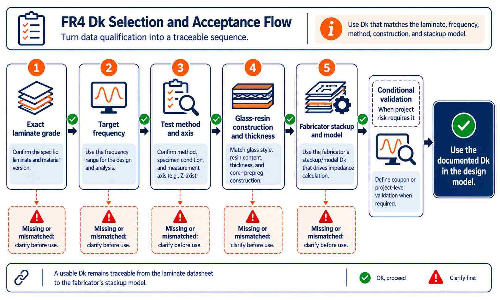
Before using a Dk value in your design, perform the following five-point check to ensure that you are using the correct Dk value for your PCB and your planned environment. Performing these checks will help you identify most mismatches before they are entered into an impedance calculator or field solver.
- Verify the exact laminate grade; verify the manufacturer's name and product designation; request clarification on any entry identified only as FR-4, high Tg, or equivalent.
- Verify the frequency of Dk; a Dk value characterized at 1 MHz used in conjunction with a design created to operate at multi-GHz frequencies can result in significant deviation from the expected value.
- Record the test method and direction of the measurements; whenever possible, use named test methods, test specimen conditions, and measurement axes to clearly identify the Dk; request clarification on the source of a Dk number that lacks supporting details on how it was obtained.
- Verify laminate construction; verify glass style, resin content, thickness of the laminate, as well as the identities of the core and prepreg. Clearly state the laminate grade and resin system associated with any cloth labels.
- A datasheet may have multiple valid values, whereas the board manufacturer may have models for a specific construction type when pressed into layers. Ask what number is used for the controlled-impedance calculation and how that number was derived. Using a datasheet value averaged with a stackup value produces a number without a defined test or design basis. For sensitive work, also define whether coupon or project-level validation is required.
Maintain one definitive engineering record: laminate grade and construction, modeling Dk, frequency, source, and stackup revision. If the fabricator changes either the resin system or the construction type, always evaluate the electrical basis before release, rather than simply maintaining the previous Dk.
PCB manufacturing capabilities can only be considered after this electrical information has been defined well enough that construction and verification are possible.
A useful request to the fabricator
Do not just inquire about the "FR-4 dielectric constant." Be sure to include the complete routing configuration: the required impedance, signal bandwidth, layer usage, final copper thickness, possible dielectric thickness, and any timing or phase restrictions. Then, go on to check the laminate manufacturer, product designation, core and prepreg construction, pressed dimensions, percentage of resin in the dielectric material, modeling Dk (Design Dk), reference frequency, test or extraction basis, and calculation assumptions.
For instance, a typical inquiry may look as follows: Please confirm the name and grade of the laminate material for layers 2 and 3. Provide information about the core material and prepreg construction; provide a nominal pressed dielectric thickness value; percentage of resin; copper profile; and the modeling Dk (Design Dk) and frequency used to calculate the 50-ohm trace.
After this, the reply has to contain the revision number of the stackup used and information on which inputs were considered while calculating impedance values. If it is acceptable to use alternative materials, any changed impedance geometry and the electrical equivalency check should be specified before production begins. For builds sensitive to tolerances, geometry of the coupons, limits of acceptance, location of the tests, and reporting structure have to be stated. It provides all the departments (including purchasing and validation) with the same history while not pretending that only a single decimal from a catalog does everything for all types of boards.
Dk Is Not Df, and FR4 Is Not Always Enough
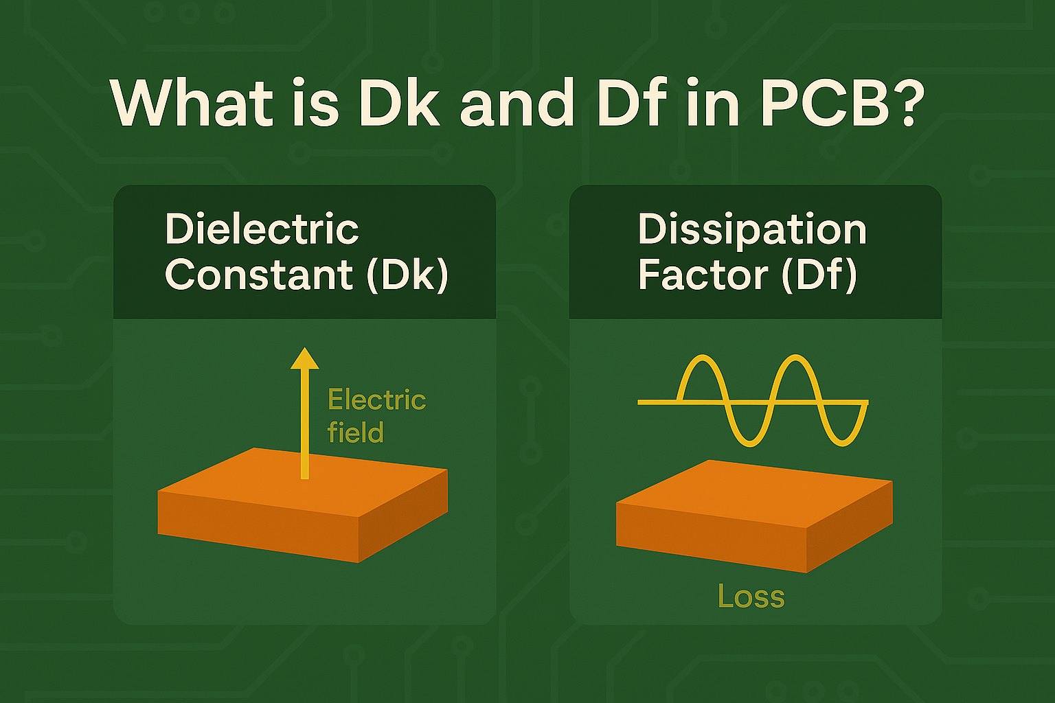
Dk influences mostly the electromagnetic field model, the impedance calculation, propagation speed, and the phase of a signal. Df is used in dielectric-loss calculations. Thus, a laminate can show a more than satisfactory Dk parameter and still miss a channel-loss criterion.
This distinction prevents a false rule as well: there is no need to switch to a Rogers laminate or a PTFE-based material at some fixed frequency above which FR-4 cannot be used. There are numerous factors influencing the choice, including the route length, the insertion-loss budget, phase stability, the tolerance of the stackup, the roughness of copper, temperature range, and production repeatability.
Standard FR-4 material can be used provided the stated grade and the approved stackup meet the objective electrical budget. Low-loss materials are considered when dielectric loss, phase stability, or repeatability requirements exceed the limits of the confirmed FR-4 construction. Such comparisons should take into account Dk and Df at the necessary frequencies, not just the material name.
Looking for deeper treatment of the materials and fabricating issues? You can find it in Rogers and PTFE RF PCB.
Frequently Asked Questions
Q1. What is the dielectric constant of FR4 7628?
There is no universal dielectric constant for FR4 7628. Indeed, 7628 describes a glass-cloth style. In Panasonic R-1766(GH) with 43% resin and a thickness of 8 mils, Dk is 4.3 at 2 and 4 GHz, and then Dk is 4.2 from 6 to 10 GHz. Each resin system or construction needs its own data.
Q2. Does FR4 Tg170 or high-Tg FR4 have a fixed Dk?
No, because Tg shows a certain thermal property, not a value for dielectric constant. Two high-Tg laminates may use different types of resin, glass construction, and test methods to produce different Dk values. Thus, it is better to select Dk according to the exact laminate grade and construction at the relevant frequency.
Q3. Which Dk should I use for an FR4 core?
The value should match the exact core grade, glass and resin construction, pressed thickness, desired frequency, and fabricator model. If there is a difference between Dk values, you should investigate the test methods and intended usage. You should not average the two resulting values.
References & Sources
- FR-4 R-1766(GH) Datasheet – Panasonic Industry
- VT-42 Process Guide – Ventec International Group
- Overview of Test Methods to Determine Material Dk and Df – Rogers Corporation
- General Information of Dielectric Constant for RT/duroid 6010.2LM and RO3010 – Rogers Corporation
- Managing PCB Materials Dielectric Constant Dk – Rogers Corporation
- Making Sense of Laminate Dielectric Properties – Isola Group