Upload BOM & Gerber

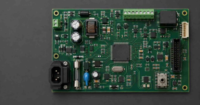
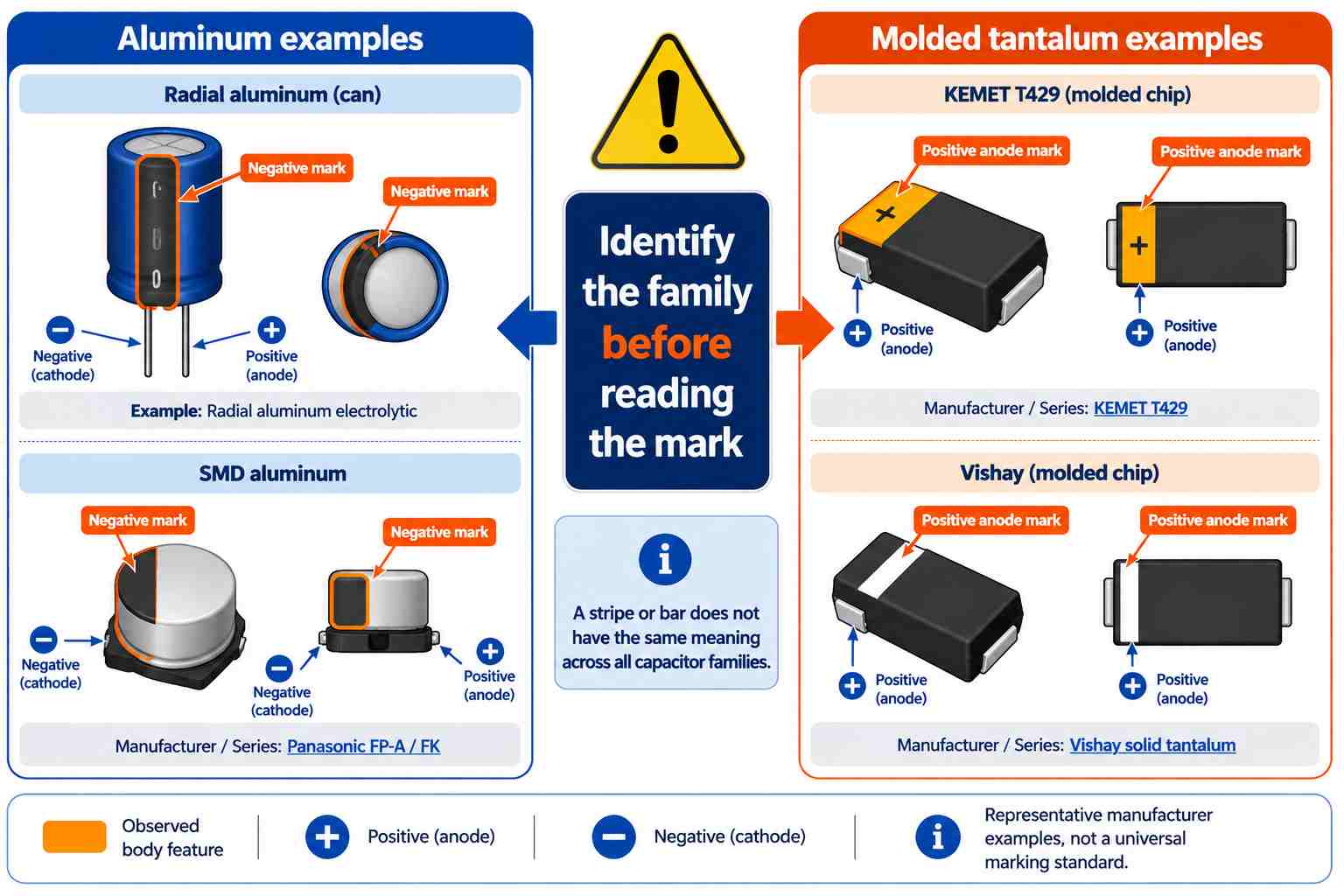
Not all capacitors are polarity-sensitive. For aluminum electrolytic capacitors, the negative terminal is often marked with a stripe on the body of the capacitor. In contrast, many molded tantalum capacitors include markings that indicate the positive anode. If you are unsure about how to orient a capacitor in your circuit, review the manufacturer's documentation for additional information regarding how to orient the capacitor in the circuit. If the part identity or orientation cannot be confirmed from the manufacturer documentation, do not solder the capacitor or connect power to your circuit until you have confirmed the capacitor's part number and manufacturer.
The external markings only provide evidence of which terminal is positive or negative. Before determining the correct orientation, confirm the capacitor's polarity from the manufacturer's specifications, then verify the PCB pad layout and soldering orientation.
Contents
show
What Determines Whether a Capacitor Has Polarity?
From a construction standpoint, whether a capacitor has specific electrical polarity depends on the internal dielectric/electrode structure and the manufacturer specification, not merely the external markings. Both standard aluminum electrolytic and tantalum capacitors typically employ an asymmetrical dielectric/electrode structure, and applying reverse voltage to either of these types of capacitors can result in increased leakage and damage to the dielectric system. Ceramic and film capacitors are non-polar families; bipolar aluminum electrolytic capacitors, such as Panasonic's KA-A series, are intended for applications where the applied voltage may reverse. (Panasonic capacitor basics; Panasonic electrolytic fundamentals).
Record the following data about the capacitor: manufacturer, series or orderable number, capacitance, voltage rating, and package. Check the manufacturer's current datasheets or catalogs for terms like "polarized," "bipolar," "non-polar," "anode," and "cathode." Just because there are no markings on the body of the capacitor doesn't mean that the capacitor can be used with either orientation.
Nichicon's application guidelines indicate that the user should view standard aluminum electrolytic capacitors as polarized and select a bipolar design where the applied voltage can reverse.
How Do You Identify Aluminum Electrolytic Polarity?
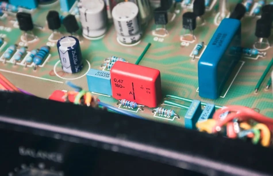
Radial aluminum electrolytic capacitors commonly identify the negative terminal with a printed sleeve band, with some new radial capacitors also having the negative lead shorter than the positive lead. Although there are indicators like the ones mentioned above, the Panasonic product catalog and product specification sheet require confirmation of polarity, terminal, and land patterns from the applicable reference prior to installing the part (Panasonic aluminum capacitor catalog).
Always confirm every indicator in its original state—once trimmed or removed, the lead length has lost its value. The sleeve printing may fade, tear, or become obscured or damaged. Axial bodies and unfamiliar variations may use a different form and can reduce the reliability of radial-can conventions for determining their proper alignment.
The perspective from which you look at the PCB layout before transferring the polarity to your land pattern can also affect the interpretation. A PCB component-side view, solder-side view, and datasheet terminal view can mirror the same two leads. To confirm the polarity, use the diagram label and locating feature identified in the datasheet, and then orient the actual unit so that its orientation matches the stated view.
When there are two weak indicators, you should return to the datasheet before assigning the polarity to your land pattern. (DigiKey polarization guide).
Tantalum Marks Point to the Positive Anode
Various molded solid tantalum families have a physical polarity indicator for the positive anode, which may appear as a bar or stripe on the molded case. KEMET's T429 datasheet identifies the polarity indicator as positive, while Vishay's tantalum FAQ describes a white bar as the anode mark. KEMET also uses molded part geometry to identify the positive end of some leaded tantalum units instead of having the reader locate an aluminum-style sleeve stripe (KEMET T340 datasheet). Vishay has also defined a plus mark for leaded solid tantalum capacitors.
How Is SMD Capacitor Polarity Shown?
Markings indicating the polarity of surface-mount devices can consist of bands, painted sections, chamfers, molded features, or other documented terminal geometries. The appearance of different markings depends on which case style is selected. For example, Panasonic provides a negative polarity mark in both its FP-A and FK drawings, while KEMET's T429 molded tantalum drawing shows a positive anode (see the Panasonic FP-A catalog and Panasonic FK datasheet).
Three views may be available in a drawing set for an SMD component: component outline, recommended land pattern, and tape/reel orientation. These three views serve different purposes: the housing outline indicates the location of terminals on the SMD; the recommended land pattern shows the location of copper pads where the component will attach to the PCB; and the orientation of a carrier helps equipment position the unit consistently.
Before placing a surface-mount capacitor, check these five items before you begin:
- Verify that the complete series and case code shown in the drawing match exactly what you have.
- Determine whether the drawing shows the top, bottom, or terminal view.
- Locate the documented polarity feature (i.e., positive or negative) and named terminal.
- Map that terminal to the recommended footprint land pattern.
- Convert the result into a top-side assembly view on the PCB.
You must document your results as full statements about the series and case being referenced. For example: "For this named series and case, the documented feature identifies this electrode in the stated view." Note: color, pad size, or isolated chamfers do not substitute for required information.
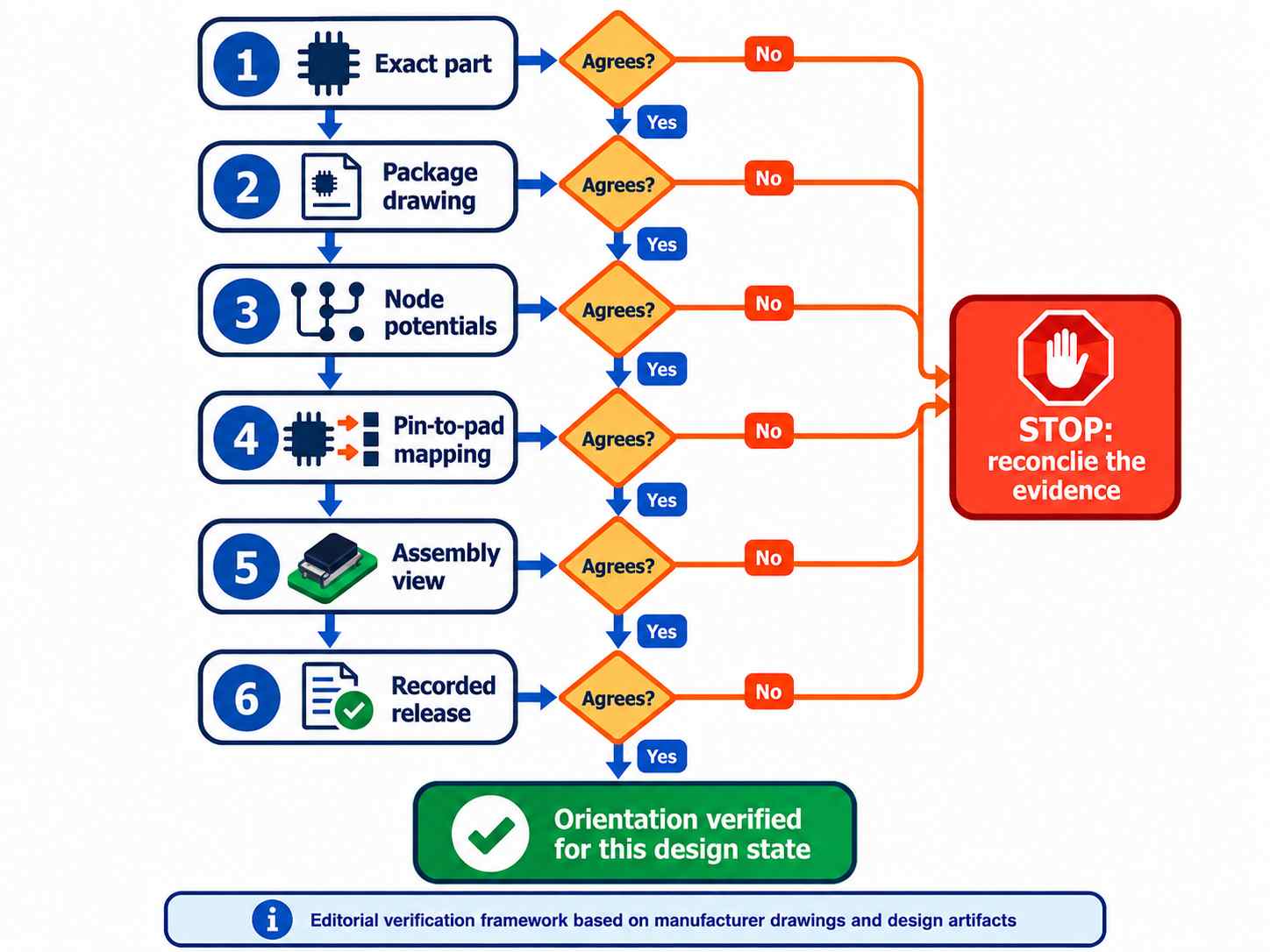
Match the Part, PCB Pads, and Circuit Potentials
Ensure that the component terminal, circuit potential, schematic pin, footprint pad, and assembly view are correctly aligned. In KiCad, the circuit symbol pins are mapped to the footprint pads via their pin numbers; therefore, the similarity of the schematic symbol alone does not guarantee the correct numeric mapping. For example, a KiCad schematic may include a "+" sign indicator for a polarized capacitor; however, that indicator alone does not confirm which physical land is positive. The pin numbers of the symbol must still be assigned to the respective footprint pads intended for placement.
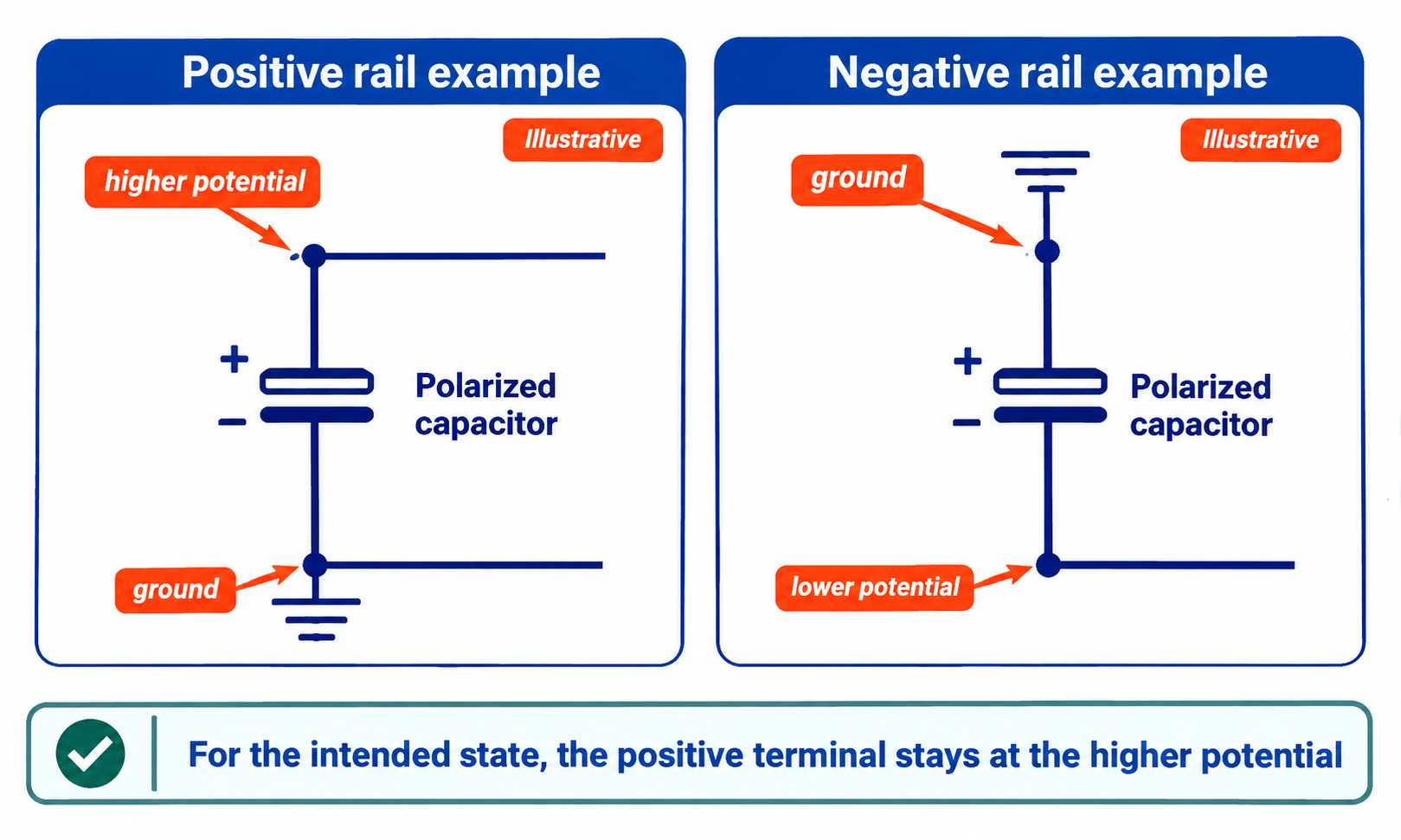
For a standard polarized capacitor, the lower-potential side is connected to its negative terminal for the intended operating condition. Although this negative terminal may be connected to a ground node, it does not need to be grounded in a circuit; for example, you could have a circuit where the capacitor's positive terminal is at ground potential and the negative terminal is connected to a negative voltage rail. When determining how to connect your capacitor in this way, make sure to consider whether the startup state, shutdown state, disconnected-source state, and fault state can result in a situation where the voltage across the capacitor will be reversed. Nichicon recommends using bipolar capacitors in circuits where the polarity may be reversed; however, there is no substitute for examining the operating conditions of the circuit to verify that the capacitor itself will not become damaged by reverse voltage. A static net name for the capacitor cannot replace this operating-condition review.
When in doubt about a capacitor's symbol or footprint identity, always check the capacitor's symbol and footprint mapping before it is released.
How Do You Verify Orientation Before Power-Up?
Altium recommends including information about the polarity and orientation of capacitors in the assembly outputs. The component datasheet is the fundamental source for the physical orientation of the capacitor (see Altium assembly documentation).
Example (hypothetical board): The BOM specifies an SMD aluminum electrolytic capacitor from Panasonic, FK series, and it specifies the exact case code for that capacitor. The drawing indicates the capacitor's negative polarity mark. The capacitor C17 is connected between +12 V and ground. The approved project library has the positive terminal of the capacitor mapped to the +12 V pad and the negative terminal mapped to the ground pad. The centroid rotation and the top-side assembly view must maintain this mapping. If, during a silkscreen or placement rotation check, you see that the negative indication is toward the +12 V pad, resolve the conflict before the release of the product.
This verification check will tell you whether the capacitor is correctly oriented; it will provide no information concerning the capacitance, ESR, leakage, or in-circuit health of the capacitor. Even though the silkscreen is correct, it cannot compensate for an incorrect footprint mapping. Similarly, if there is a schematic change, the voltage relationship established by a particular copper trace may no longer be valid even though the copper trace has not physically moved.
Release documentation must include all relevant information about a part; this includes the exact supplier, series, case, datasheet view, schematic reference, pin-to-pad mapping, relevant net voltages, and placement perspective. The term "stripe left" will not communicate this necessary information since it does not include the family of the part, the view of the part, the library version of the part, or the electrical context of the part.
If there is a conflict between your BOM, library designation for the part, pad identification, and assembly output of the part, you must address the engineering-data conflict prior to releasing the part for production. If the schematic, footprint, or library is the source of the data, then you may want to consider engaging a PCB design services; never use the first power-up as a means of reconciling a polarity conflict.

What Happens If a Polarized Capacitor Is Reversed?
Reverse voltage can cause an increase in leakage current, heat buildup, and internal gas production in aluminum electrolytic capacitors. Nichicon states that leakage current will increase and vent operation is possible. Panasonic states that reverse voltage can cause degradation, leakage, venting, ignition, or explosion under certain conditions (Nichicon technical notes; Panasonic safety guide). The outcome of these conditions is not a universally timed event and depends on part construction, reverse voltage, time under reverse voltage, temperature during reverse polarization, source impedance seen by the part, and total amount of energy available to the part. TDK has also advised designers to prevent reverse polarity in aluminum electrolytic applications (TDK General Technical Information).
If you are unsure of the orientation of the component after soldering has occurred, remove power from the circuit and follow the documented safe-state procedure for the product. Recheck the exact part and design documentation before determining whether the component can remain on the board. You should not conduct a deliberate reverse-polarity test on the fully assembled board.
Replacement Checks When the Original Direction Is Unclear
Before removing a polarized capacitor, evidence that indicates its orientation should be kept. This can be done by photographing the entire PCB, taking close-up views of the capacitor, recording its reference designator, documenting all markings on the capacitor body, and recording the position of PCB alignment cues with respect to the capacitor terminals. The record you make will allow you to compare this to the new part, but the mechanical drawing of the new part will remain the authoritative source.
Your record of the replacement should include the following information:
- The PCB ID and Reference Designator
- The Manufacturer's Name, Series, Value, Voltage Rating, and Case Code of the Old Part
- The Stripe, + (plus), Molded Feature, and Direction of These Markings as Viewed on the Board Side
- The Polarity Cue on the PCB, Pad Numbers, and Connected Net Names
- The Replacement Manufacturer, Exact Series, Case Code, and Package View
- The Final Decision on the Orientation of the Replacement Part and the Evidence Used to Make This Decision
In the case that the old capacitor is no longer present, DO NOT IMITATE THE DIRECTION of any nearby capacitor. Just because components look similar does not mean they will connect to the same rails, and symmetric layouts do not provide a guarantee of equal potentials on both sides. Recreate your answer using the schematic, netlist, footprint mapping, copper traces on the PCB, and the approved assembly documentation.
PCB assembly visual inspection by production personnel and AOI of the PCB assembly both rely on comparing visible orientation to what was approved prior to manufacture; AOI is automated to determine whether there is a mismatch between the approved reference and the actual part installed. However, both methods rely upon the accuracy of the reference to which each method refers; therefore, if the polarity rule, footprint mapping, or golden-board criteria are incorrect, the inspection methods can continue to accept a capacitor installed in the wrong orientation. Settle the package drawing and design mapping first, then use AOI to identify deviations from the approved reference.
Any independent confirmation of a different mounting direction indicates that the process is not yet complete.
Frequently Asked Questions
Q1. Can a multimeter identify an unknown capacitor's polarity?
Not reliably from generic capacitance, resistance, or continuity measurements. Fluke recommends that you power down, verify that the circuit is dead, discharge the capacitor, and remove the component from the circuit when needed to avoid measurement errors (Fluke capacitance guide).
Some guides suggest using resistance or charge comparisons when switching the leads around; however, resistance and charge readings depend on the design of the test meter, the amount of charge stored on the component, the parallel circuit paths present, and the condition of the capacitor.
For instance, in the case of tantalum chip capacitors, leakage paths within the component can cause the forward and reverse readings to differ by only a small amount, which is easy to misinterpret as having no polarity. The manufacturer's documentation should be referenced to determine the polarity of a capacitor.
Q2. Does a zero-ohm or continuity reading reveal capacitor polarity?
A continuity or zero-ohm reading alone leads to no universal conclusion regarding the polarity of a capacitor. First determine that the circuit is in its documented safe condition and then separate the test procedure for the capacitor from the orientation decision. The manufacturer's marking drawing contains the primary evidence of the capacitor's identified polarity.
Conclusion
Name the exact series and family of the capacitor, read the package drawing, confirm the relative potentials of the circuit, track the symbol pins to their respective footprint pads, and verify that your orientation matches the drawing. If you are uncertain or cannot find the required information for a particular layer, STOP until everything is confirmed before soldering or applying power to the circuit.
References & Sources
- KA-A Series – Panasonic Industry
- Basic Knowledge of Capacitors (2) – Panasonic Industry
- Fundamentals of Capacitors and Hybrid Capacitors – Panasonic Industry
- Aluminum Electrolytic Capacitors Application Guidelines – Nichicon
- Surface Mount and Radial Lead Aluminum Electrolytic Capacitors – Panasonic Industry
- Identifying Capacitor Polarization – DigiKey
- T429 High Temperature Tantalum Capacitors – KEMET
- Frequently Asked Questions for Solid Tantalum Capacitors – Vishay
- T340 Molded Radial Tantalum – KEMET
- FP-A Series – Panasonic Industry
- FK Series – Panasonic Industry
- Eeschema Reference Manual – KiCad
- Documenting Your PCB Assembly – Altium
- Technical Notes on Aluminum Electrolytic Capacitors – Nichicon
- Safety Application Guide for Aluminum Electrolytic Capacitors – Panasonic Industry
- General Technical Information – TDK Electronics
- How to Measure Capacitance with a Digital Multimeter – Fluke