Upload BOM & Gerber
-
Mobile: +86 13312967631
-
Email: sales@sugaintl.com

Flexible PCB Manufacturer (FPC)
Custom Flex PCB Manufacturing — Fine-Line, Extra-Long, Dynamic FPC
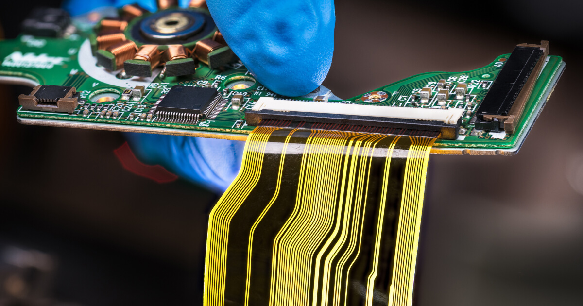
SUGA manufactures custom Flex PCBs for compact electronic devices, shaped interconnect applications and repeated-motion applications. The manufacturing process of Flex PCBs extends from bare FPCs through component assembly for fine-line, long-routing and dynamic-flex constructions.
FLEX PCB SPECIFICATIONS
1–12 LayersStandalone FPC
2 / 2 milFine line at 12 µm Cu
Up to 3,000 mmExtra-long FPC
±5%Controlled impedance available
100% Electrical TestContinuity and isolation
100,000+ CyclesDynamic flex with RA copper
Why Choose Flexible PCBs?
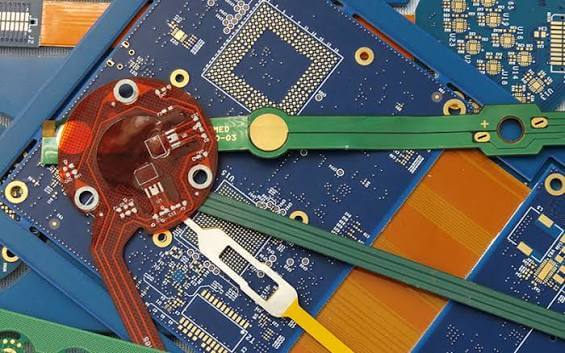
Flexible PCBs provide an advantage because they allow one continuous circuit to complete functions that previously required one or more rigid boards, one or more cable assemblies and one or more board-to-board connectors. They can also reduce separate electrical interconnects between multiple flat planes, allowing greater routing density in the same footprint as traditional interconnection methods.
REAL DESIGN QUESTION
“I want to add a flex cable to my project so I don't need to run 38 wires between 2 boards…”
Source: r/PrintedCircuitBoard — custom flex interconnect discussion
Fit More Electronics into Less Space
Up to 3,000 mm Extra-Long FPC
Continuous routing can pass between offset modules, curved housings and long or narrow spaces without separate cable runs.
Replace Cables and Connector Interfaces
One Continuous Flex Interconnect
Flexible circuit technology allows multiple connections to be combined into one continuous flexible interconnect.
Carry Signals Through Repeated Motion
RA Copper · 100,000+ Cycles
Dynamic-flex constructions for hinges, moving heads and sliding assemblies support circuits that flex during operation.
Increase Routing Density in Compact Products
2 / 2 mil at 12 µm Cu
Fine-line routing supports high routing density in compact products where board area and routing channels are limited.
Flex PCB Types & Materials
The number of layers in a PCB increases routing density, while the finished thickness and copper construction help determine the minimum bend radius and flex life. As the number of conductive layers and moving-stack thickness increase, bend requirements also increase. The use of thinner moving stacks and RA copper is important for repeated flexing.
SUGA Flex Construction Range
The 6× / 12× / 24× ratios use the total flex thickness of the circuit. Dynamic flex is not a construction type but a motion duty, while extra-long FPC is a dimensional capability rated separately.
| Construction | Conductive Layers | Interconnection | Min Bend Radius | Typical Application |
|---|---|---|---|---|
| Single-Sided FPC | 1 | Single conductive side | ≈ 6× flex thickness | Sensors · lighting · simple jumpers |
| Double-Sided FPC | 2 | Plated interconnects | ≈ 12× flex thickness | Displays · wearables · camera links |
| Multilayer FPC | 3–12 | Multilayer PTH | ≈ 24× flex thickness | Camera · medical · dense modules |
Flex PCB Materials and Stackup
Both PI and PET substrates are supported by SUGA. PI is ideal for multilayer FPCs because of its thermal stability and for applications where FPCs are subjected to repeated flexing. PET, in contrast, is best suited for static flex situations where the operating and processing temperatures are acceptable for the product being manufactured.
An adhesive laminate adds a core layer of adhesive that bonds the dielectric layer to the copper layer of the PCB. By removing the core adhesive, adhesiveless polyimide can reduce the finished thickness of the PCB compared with an adhesive laminate. Coverlay adhesives and structural stiffener bonding layers can still be present in the final FPC.
Because of the ductility of RA copper, it works best in applications in which the copper conductor is repeatedly flexed. The orientation of the foil is also important, as it relates to the bend direction. ED copper remains suitable for static applications.
Polyimide coverlay provides protection of the conductors and electrical insulation. The coverlay uses polyimide film and adhesive while remaining part of the flexible stack. SUGA also provides an 18 µm shielding film for EMI and EMC control. When shielding film adds thickness to the flex stack, the added thickness must be considered where the flex section bends.
SUGA Flex PCB Manufacturing Capabilities
SUGA's Flex PCB Manufacturing provides customers with three tiers of manufacturing capabilities for separating routine production from advanced production and engineering limits. Routine production is classified as "Standard," advanced production is classified as "Best," and the engineering limit is classified as "Maximum." The maximum values for each tier are independent of each other and cannot be combined to produce a single FPC stackup.
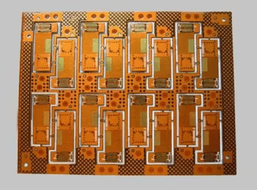
The finished-size limit for conventional FPCs is 500 × 600 mm, while the maximum capability for extra-long FPCs is 3,000 mm.
The copper thickness must also be considered in conjunction with the three-tier trace/space envelope for flexible PCBs. At a copper thickness of 12 µm, 3 / 3 mil is classified as Best, while 2 / 2 mil is classified as Maximum. Routine geometry is 3.5 / 3.5 mil at 18 µm and 4 / 4 mil at 35 µm.
Core Specifications
| Parameter | Standard | Best | Maximum |
|---|---|---|---|
| Layer Count | 1–2 | 2–6 | 12 |
| Base Material | Polyimide | PI · Adhesive / Adhesiveless | High-Reliability Flex Material |
| Board Thickness | 0.08–0.20 mm | 0.05–0.30 mm | Project-Specific |
| Copper Thickness | 0.5–1 oz | 0.5–2 oz | 3 oz |
| Copper Foil Type | ED Copper | RA Copper | High-Flex RA Copper |
| Min Trace / Space | 4 / 4 mil | 3 / 3 mil | 2 / 2 mil |
| Min Mechanical Hole | 0.25 mm | 0.20 mm | 0.15 mm |
| Min Laser Via | 0.10 mm | 0.075 mm | 0.050 mm |
| Hole Copper Thickness | ≥15 µm | ≥20 µm | ≥25 µm |
| Conventional Finished Size | 250 × 400 mm | 400 × 500 mm | 500 × 600 mm |
Finishing & Reliability
| Parameter | Standard | Best | Maximum |
|---|---|---|---|
| Surface Finish | ENIG · OSP | ENIG · Imm. Ag · Imm. Sn | ENEPIG · Selective Gold · Electroplated Gold |
| Coverlay Color | Yellow · Black | + White | Custom |
| Stiffener Material | PI · FR4 | + Stainless Steel | Aluminum · Steel · Custom |
| Dynamic Bend Cycles | 1,000+ | 10,000+ | 100,000+ |
| Impedance Control | ±10% | ±8% | ±5% |
| Testing | 100% E-Test | + AOI · Flying Probe | + TDR · Reliability |
| Gold Finger | Available | Selective Hard Gold | High-Durability |
Independent Precision and Dimensional Limits
| Engineering Parameter | SUGA Capability |
|---|---|
| Board Outline | ±0.10 mm routine · ±0.05 mm precision |
| Reinforced Area ≤0.30 mm | ±0.05 mm |
| Reinforced Area 0.30–1.00 mm | ±0.10 mm |
| Gold Finger Insertion Area | ±0.03 mm |
| PI Stiffener Thickness | 0.10 · 0.15 · 0.20 · 0.225 · 0.25 mm |
| Extra-Long FPC Length | Up to 3,000 mm |
SUGA Dynamic Flex Reliability: Bend Radius, Copper and Cycle Life
SUGA combines flex cycle life, bend radius, copper foil and conductive-layer count to define the moving FPC construction.
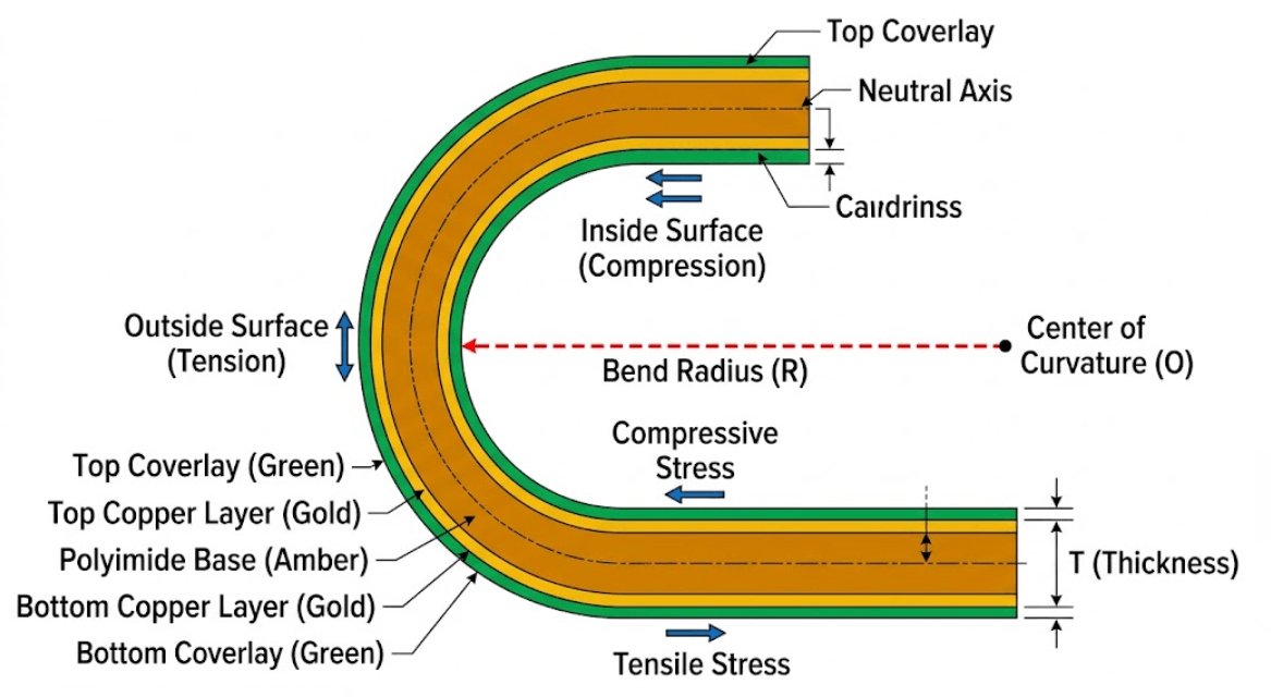
SUGA Bend-Radius-to-Cycle Map
SUGA's 100,000+ cycle capability is based on a defined RA-copper moving construction with a predetermined bend radius.
| Flex Duty | Bend Cycles | Dynamic Radius Reference | Copper Foil | Conductive Layers |
|---|---|---|---|---|
| Light Dynamic | 1,000–10,000 | ≥10× thickness | RA preferred | 1–2 |
| Dynamic Flex | Cycle-defined | ≈100× thickness | RA | 1–2 |
| High-Cycle Dynamic | 100,000+ | Construction-specific | RA | 1–2 |
Dynamic Bend Radius Reference
These references should not be used to convert thickness alone into cycle life.
0.195 mmFinished Flex Thickness≈ 19.5 mm100× Dynamic Radius Reference
0.220 mmFinished Flex Thickness≈ 22.0 mm100× Dynamic Radius Reference
Engineering Insight
It cannot be expected that adding thicker copper will automatically produce longer dynamic-flex life. Repeated bending favors thinner RA copper because additional copper thickness and moving-stack thickness increase strain at the same bend radius.
Every layer added to the FPC bend stack increases the total moving thickness. Coverlay, adhesive and shielding layers increase the finished bend-stack thickness, so the bend radius is based on the complete FPC flex section rather than the PI core alone.
Bend-Zone Rules
The features listed below should be kept outside the repeated-bend region to minimize local strain concentration.
No vias
No stiffener edges
No rigid components
Gradual copper transitions
Flex PCB vs Rigid PCB with Cable Assembly: Performance and Total System Cost
Flex PCB costs per board are generally higher than rigid PCB costs; however, the overall interconnect cost should include cables, connectors, assembly interfaces, weight and packaging space.
Reference values are illustrative and are not SUGA first-party measurements; actual results vary by product architecture.
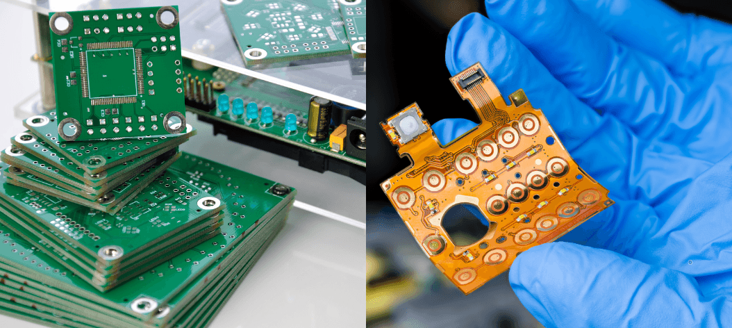
Flex vs Rigid-and-Cable System Comparison
| System Factor | Flex PCB | Rigid PCB with Cable Assembly |
|---|---|---|
| Laminate Cost | 2–3× FR-4 material cost | 1.0× baseline |
| Finished Board Cost | 3–8× comparable rigid board | 1.0× baseline |
| Interconnect Points | 80 in published 20-circuit example | 120 in wired 20-circuit example |
| Interconnect Weight | ≈10% of comparable wired solution | 100% wired baseline |
| Packaging Space | ≈10% of comparable wired solution | 100% wired baseline |
| Interconnect Architecture | 1 continuous flex path | PCB · Cable · Connector |
The Bare-Board Price Is Not the Installed Interconnect Cost
A higher flex-board price can be offset when the architecture eliminates separate cable assemblies, connector pairs and related assembly interfaces.
Installed Interconnect Cost = PCB + Cables + Connectors + Assembly + Test
A rigid PCB with a separate cable assembly may still provide more value when modular field replacement and the lowest bare-board price matter more than space, weight or interface reduction.
Flex PCB Applications
The way a Flex PCB is constructed, including its bend characteristics, is determined by motion and the physical configuration of each application, not simply by the industry to which the application pertains.
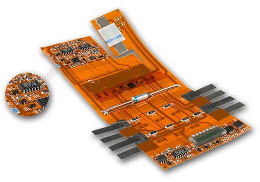
Wearables and Medical Devices
Wearables, patient monitors and hearing aids require thin, lightweight interconnects that fit in body-worn or tightly constrained spaces without creating cable clutter. PI-based FPCs can use PI, FR4 or metal stiffeners in situations where local reinforcement is required, usually in the connector or component area.
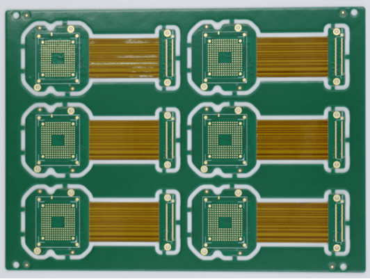
Cameras and Compact Electronics
Camera modules, compact displays and foldable electronics typically utilize multiple offset modules in close proximity within a small enclosure with a routing layout. FPCs utilizing 12 µm copper allow a camera interconnect of 3 / 3 mil in the Best production process or 2 / 2 mil in the Maximum production process.
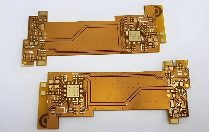
Industrial Motion and Automotive Electronics
Printer heads and moving carriages place repetitive movement, vibration and motion endurance at a higher priority than simple board density. An FPC utilizing dynamic-flex RA copper can provide repeated-motion connections specified for 100,000+ bend cycles.
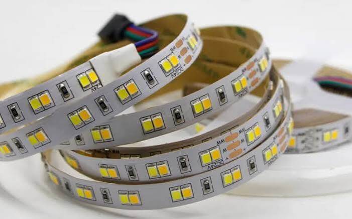
Displays, Lighting and Long Interconnects
Shaped displays, LED lighting and distributed modules may require a continuous circuit through non-planar or long housing configurations coupled with current and thermal loads. Extra-long FPC is available up to 3,000 mm for continuous routing through long or non-planar housing configurations.
SUGA Flex PCB Quality, Testing and Certifications
Quality testing and credentials should be based upon auditable standards such as IPC-6013F, coupled with certified quality systems and product-level verification for electrical, dimensional, impedance and motion performance tied to the delivered flex PCB construction.
IPC-6013FFlex PCB qualification and performance
ISO 9001Quality management system
ISO 13485Medical quality management system
IATF 16949Automotive quality management system
100% Electrical TestContinuity and isolation
ULCertification
IPC Type, Performance Class and Flex Duty Are Different Specifications
IPC Type, Performance Class and flex duty are separate specification axes; a higher performance class does not by itself define dynamic-flex cycle life.
IPC TypeType 1–5Construction
Performance ClassClass 1–3Acceptance
Flex DutyStatic · DynamicMotion
SUGA Flex PCB Verification Data
Each method verifies a different property; electrical continuity does not establish impedance or dynamic-flex life.
| Quality Field | Verification | SUGA Data |
|---|---|---|
| Material Stackup | Material ID · Stackup Record | PI · PET · RA · ED |
| Electrical | Continuity · Isolation | 100% |
| Fine Geometry | AOI · Dimensional | 2 / 2 mil @ 12 µm Cu |
| Controlled Impedance | TDR | ±5% Available |
| Dynamic Flex | Bend-Cycle Test | 100,000+ · RA Copper |
Flex PCB Cost and Procurement
When a buyer reviews multiple Flex PCB suppliers, they should first normalize the same construction, quantity, verification scope and delivery terms before making cost comparisons.
What Actually Moves a Flex PCB Quote?
01
Layer Count
The more layers a PCB has, the more work is involved in laminating, registering and creating interconnections. If there are unnecessary layer pairs, eliminating them may provide a simpler fabrication process.
02
Copper and Fine Geometry
Standard 4 / 4 mil, Best 3 / 3 mil and Maximum 2 / 2 mil define the purchasing envelope. Copper thickness can still affect the achievable trace/space geometry.
03
Via Structure
Through-holes are the baseline interconnection. Blind, buried, laser or unusually small vias typically require additional drilling, lamination or imaging steps, thereby increasing fabrication complexity.
04
Panel Utilization
Irregular outlines and requested array configurations can limit the usable panel area. Therefore, more material is allocated to each finished circuit when less panel area is utilized.
05
Finish, Local Materials and Test
If you add stiffeners, shielding, PSA or premium finishes, or require additional qualification, then there will be more costs associated with the additional materials and verification.
From Factory Quote to Landed Cost
Landed Cost = Fabrication + Assembly (if included) + Freight + Duties/Taxes + Brokerage/Handling
Compare quotes based on the same delivery scope and destination basis; duties, taxes and logistics charges vary by market and timing.
When Flex Assembly Changes the Purchasing Comparison
When comparing assembled flex, compare bare FPC, component assembly and electrical test separately or together.
What to Send for a Quote
- Gerber or ODB++ plus stackup, copper and material requirements
- Bend duty: static or dynamic, with radius, travel and cycle target
- Quantity and delivery form
- BOM and placement drawing when flex PCB assembly is included
Flex PCB Manufacturer Frequently Asked Questions
How do you evaluate a flex PCB manufacturer?
Compare the same construction, copper, trace/space, bend duty, impedance target, verification scope and delivery basis. Flex PCB suppliers should indicate which values are Standard production, which are Best advanced capability and which represent Maximum engineering limits.
What is a flex PCB?
A flex PCB, or FPC, is a printed circuit with patterned conductors on a flexible insulating construction. The flex PCB can follow a particular shape or provide controlled motion depending on the materials and stackup designed for the application.
What is the difference between rigid and flex PCB?
A rigid PCB provides a fixed mounting platform, whereas a flex PCB provides a formed or moving interconnect path. This is useful when space, motion or connector reduction changes the system design.
What is the difference between a flex PCB and a rigid-flex PCB?
A flexible circuit with local stiffeners is still a flexible circuit. A rigid-flex printed circuit board integrates rigid and flexible electrical regions in one laminated construction.
What are the downsides of using flexible PCBs?
Flexible circuit boards utilize thinner materials, including coverlay, local reinforcement and bend-specific design rules, so the fabrication and handling of a flexible circuit board are more demanding than those of a simple rigid PCB. Repair and local replacement can also be less convenient in highly integrated designs.
How many layers can a flex PCB have?
SUGA supports 1–12 conductive layers. Having multiple conductive layers on a flexible circuit board increases the ability to route and shield signals, but also increases the thickness of the finished assembly and reduces bend freedom, especially in repeated motion.
How thick is a flex PCB?
Thickness can mean the core film, the finished bend area or the reinforced connector area. In the two-layer examples used here, a 25 µm core totals about 0.195 mm and a 50 µm core about 0.220 mm before a local stiffener is added.
Can flex PCBs have vias?
Yes. A routine two-layer hole / pad option is 0.30 / 0.55 mm, while a 0.15 / 0.35 mm four-layer option is available for denser routing. It is preferable to keep vias outside the active repeated-bend area.
What is the maximum temperature a flex PCB can withstand?
There is no single universal operating temperature for flexible circuit boards. Pyralux AP9121 has a typical Tg of 220°C and a Pass result for solder-float testing at 288°C for 10 seconds. However, the Tg value and the 10-second solder-float testing result do not represent a continuous operating-temperature rating for the finished circuit.
How are flex PCBs made?
A typical construction sequence includes material preparation, conductor imaging and etching, drilling and plating, layer bonding and coverlay, reinforcement and surface finish, followed by profiling, inspection and electrical test. Depending on the via structure and stackup of the flexible PCB, the actual construction sequence may vary.
What attachment methods are used for flex PCB stiffeners?
Flex PCB manufacturers use several attachment techniques for stiffeners, including pressure-sensitive adhesive and heat-and-pressure bonding with a suitable thermosetting adhesive. The selection of the bonding method depends on the stiffener material, operating environment and required bond.
Can exposed adhesive attach a flex section to an enclosure?
Yes. A specified pressure-sensitive adhesive area can secure the flex to an enclosure surface when the adhesive matches the housing material and service temperature. Any intended moving area should remain mechanically free.
Is pre-baking required even if boards arrive vacuum sealed?
Vacuum packaging alone does not determine whether pre-baking is required before heat processing. Material, finish, bonding system, storage history and soldering profile should be considered because absorbed moisture can cause blistering or delamination during heating.
Is it best to panelize a flex board or leave it to the fabricator?
The fabricator develops production panelization based on the required delivery form and material utilization. The customer or assembly partner provides array dimensions, rails, tooling and equipment constraints that downstream handling must meet.
What is the cost difference between Class 2 and Class 3 flex PCBs?
The cost difference between Class 2 and Class 3 flexible PCBs cannot be generalized as a fixed percentage. The price difference comes from the acceptance, inspection, test and process-control requirements applied to the same construction.
Can flex layers overlap without being fully laminated together?
Yes. Loose-leaf or air-gap construction can leave selected flex layer groups unbonded where a fully bonded stack would restrict movement. The layer groups, interconnections and bend geometry must be designed for that arrangement.