Upload BOM & Gerber

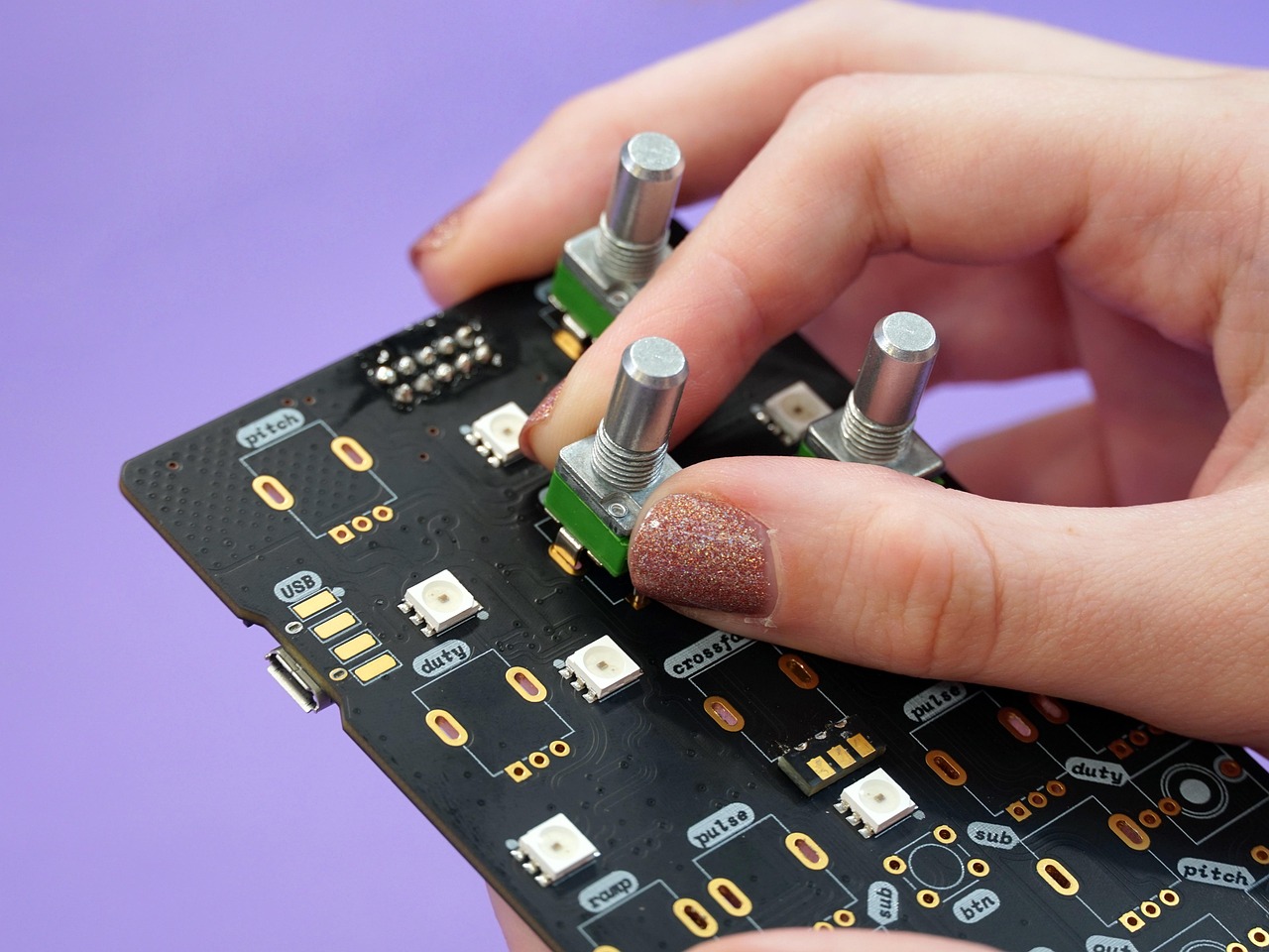
The name given to a piece of board-level hardware can vary among engineering files. A drawing for a specific piece of hardware might refer to it as a CCA, while a supplier’s quotation may refer to the same CCA as a PCBA. In most cases, they are referring to the same populated board, and the deliverables are documented via the part number, revision number, BOM, assembly drawing, test requirements, and release records.
- A circuit card assembly usually means a populated board-level assembly, not a bare printed board.
- Revision B of MIL-STD-11991 provides a document-specific example in which CCA, PBA, PCA, PCBA, PWA, and PWBA are treated as synonyms.
- The acronym identifies the object class; controlled files define included hardware, programming, inspection, testing, and release status.
Contents
show
What Is a Circuit Card Assembly?
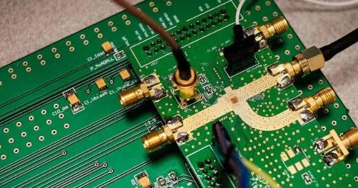
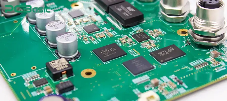
A CCA is a PCB onto which the components required to perform its assigned electronic function are populated. The CCA may contain both surface-mount and through-hole components, connectors, programmed devices, and specified mechanical or protective features.
MIL-STD-11991B §3.56 defines PWA as a generic assembly that uses a printed circuit board to mount and interconnect components. Revision B uses CCA, PBA, PCA, PCBA, PWA, and PWBA synonymously within that document and groups Circuit Cards, PCBs, and PWBs at the printed-board level. The currently active revision is MIL-STD-11991C, and contracts must indicate which revision of MIL-STD-11991 applies.
The most up-to-date English revision of the IPC terminology standard is IPC-T-50P. While contracts, customer drawings, and program glossaries can include preferred terms, they all start from the basic physical level: a bare circuit board becomes a board-level assembly when the specified components are added.
Are CCA and PCBA the Same?
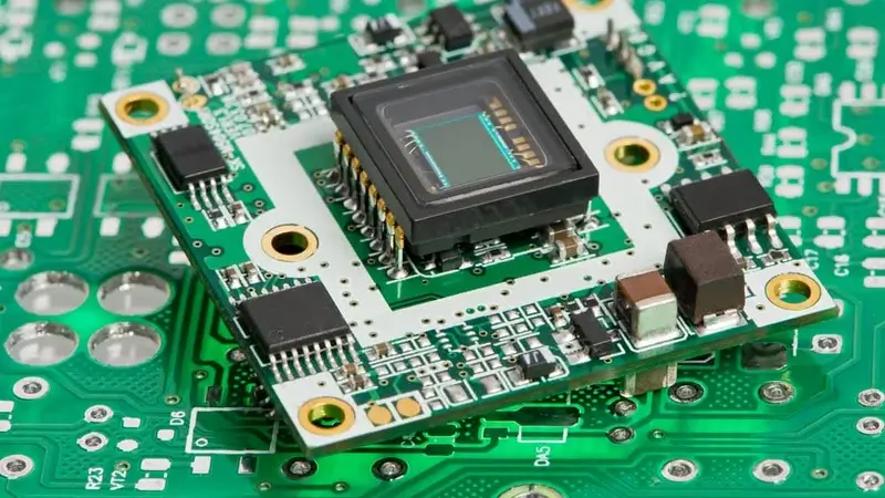
While both CCA and PCBA often describe the same physical class of object, meaning a populated printed circuit board, their usage differs primarily by the document ecosystem in which each term appears.
Two quotations may use different acronyms to describe the same populated circuit card but may actually refer to different scopes of work. For example, one quotation may include programming, coating, functional testing, and serialized release records, while the second quotation may end after assembly acceptance inspection. When confirming the hardware against the BOM, drawing, and item definition, also verify the test specification and acceptance records of the item.
How Do PCB, PWB, PCBA, CCA, PWA, and Module Relate?
Before interpreting an acronym, review the physical hierarchy to understand how the various terms relate to one another. Terms that apply to the same physical level may overlap, but higher-level terms typically contain additional information related to mechanical, thermal, wiring, or system content.
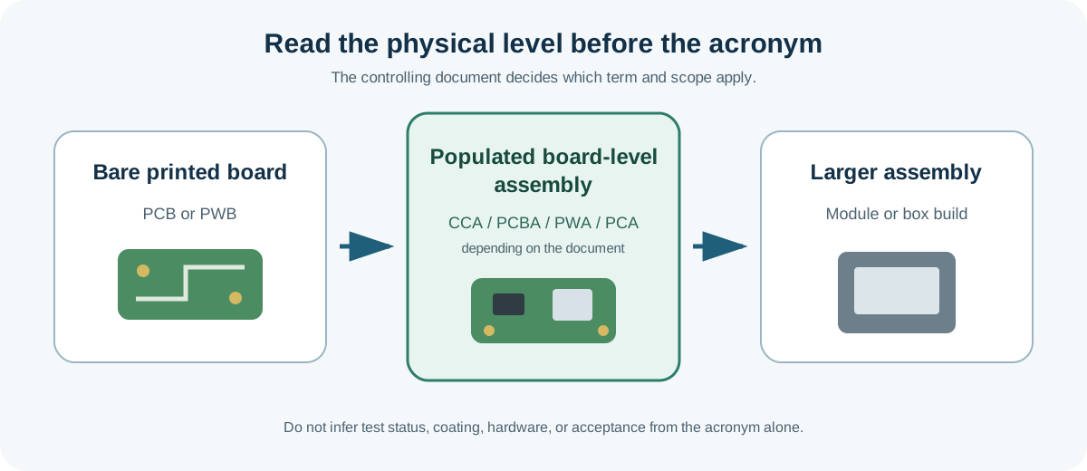
Other programs or projects may define the same acronyms in other ways or restrict their use to only certain types of equipment. Module, ECA, and LRU should not be assumed to be automatic higher-level classifications. One organization may keep a heat-sink-equipped circuit card under the part number for CCA, while another organization may release it as a separate module. A CCA, in general, can be a replaceable component but does not automatically become an LRU.
What Can a Circuit Card Assembly Include?
A CCA is usually made up of a populated circuit board that has been produced according to the orderable configuration for that assembly, including any specified connectors, stiffeners, shields, coating, labels, and associated release records. The same circuits and items can therefore be manufactured as commercially available board assemblies or, in the case of defense or aerospace products, in a configuration that includes additional mechanical protection and controlled documentation.
An example is a vibration-damped CCA made for NASA. The configuration consists of a populated circuit card combined with a metal containment enclosure and vibration-damping material. The example shows that mechanical hardware can be a component of one CCA design and is not a specification requirement for all CCA designs.
Differences in packaging and documentation for populated circuit boards can create confusion even when the assembly is properly designed and assembled. If the item definition omits ESD handling and packing requirements, the assembly may be exposed to uncontrolled handling after inspection. Therefore, the hardware’s ESD classification, packaging and labeling methods, and required shipping records should be identified before the assembly’s official release from the manufacturing facility to avoid lot isolation and additional incoming disposition.
How Is a Circuit Card Assembly Manufactured and Verified?
CCA manufacturing is the same as PCBA manufacturing, except for the terminology. After the board data, BOM, placement data, assembly drawing, and test files are released, all materials and revisions are verified before component attachment using surface-mount, through-hole, wire-bond, press-fit, or other designated methods. The final inspection and verification steps depend on the configuration. Typical inspection and verification controls include solder-paste inspection, visual inspection, AOI, X-ray, ICT or flying-probe testing, programming verification, and functional testing. All additional operations, such as coating, staking, mechanical hardware, serialization, and final documentation, will be conducted only as required by the assembly definition.
Buyers should differentiate between acceptable workmanship and product function. While a conforming solder joint indicates soldering quality, it does not indicate that firmware is functioning correctly. Likewise, although a passing functional test indicates that the board is functioning according to specifications, it does not necessarily identify all hidden solder or component defects. Therefore, a combination of these checks is required for PCB assembly tests and inspections.
Why Does CCA Appear in Aerospace, Defense and Maintenance Records?
NASA Goddard currently uses this term in its electronics rework capability descriptions, while many military maintenance programs use circuit-card terminology for board-level diagnosis and repair. As an example of this use by the U.S. Marine Corps, the Circuit Card Assembly Test Station was created to allow technicians to locate problems and repair circuit-card assemblies used in radios, power systems, vehicles, optical systems, and other types of equipment.
Maintenance records may show an item as a CCA, while the supplier database shows the same configuration as a PCBA. Cross-reference each accepted term to the same part number, revision, and effectivity so that lookup delays are avoided and differences in naming between CCA and PCBA are not mistaken for configuration differences. When a card is managed as a separate configuration item, its inspection records, failure history, repair actions, and return-to-service documentation remain attached to the card identification. The acronym alone does not establish that the item is military-grade, field-repairable, or environmentally screened.
Where Does a CCA End and a Module Begin?
A CCA generally ends at the defined board-level item, while a module begins when a separate item definition adds hardware or functions located above the CCA, such as an enclosure, thermal frame, shielding, connectors, wiring, a power-conversion stage, or multiple cards. Box-level assemblies go a step further and integrate CCAs or modules into a chassis with all applicable system interfaces.
The boundary matters in the event of a failure involving shared hardware between board assembly and system integration. Thus, if a connector is located on the CCA BOM, the installation and soldering of that connector fall within the scope of the board-level deliverable, while any connector added through a harness falls under the higher-level item of system integration. This same rationale applies to heat sinks, firmware loading, coating, and functional acceptance. Each applicable BOM, drawing, and test specification should state who supplies the associated product feature and how it is accepted. A lack of documentation clearly defining such boundaries can result in a technical failure developing into a dispute over responsibility.
How Should You Interpret CCA in a Drawing or Purchase Order?
Interpret CCA based on its relationship to the controlled item. Do not interpret CCA as shorthand for the released files.
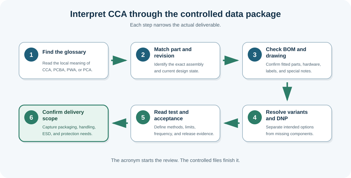
- Find the project-specific terms and definitions in the glossary to verify how the organization correlates CCA with PCBA, PWA, PCA, or local terms.
- Match the assembly P/N, revision, and effectivity, and confirm the exact configuration for purchase or repair.
- Check the BOM, variants, and DNP instructions to verify fitted parts, approved alternatives, omitted placements, and included hardware.
- Review the assembly drawing and all associated notes to confirm orientation, polarity, labels, fasteners, coating, staking, masking, and defined workmanship standards.
- Review programming, inspection, and test files to identify firmware, fixtures, conditions, limits, sampling or frequency, and result fields.
- Confirm release and delivery evidence, including serialization, nonconformance approval, repair history, ESD packaging, and records maintained as required.
The example shows how the same item name can describe a different deliverable when the revision, included hardware, programming, test, or release package changes.
What Term Should Your Team Use in Its Documentation?
Use the customer’s governing term when the glossary or contract defines it. Otherwise, write out circuit card assembly on first use, identify the physical boundary, and keep the part number and revision beside the name.
- Use one preferred term consistently within the released document set.
- Define whether the item is a bare board, populated board, module, or equipment-level assembly.
- Control coating, hardware, firmware, inspection, testing, and packaging in their proper files.
- Do not use CCA, PCBA, PWA, or PCA as evidence that a named test or release step has been completed.
Clear wording example: “CCA means the populated board identified by assembly part number A1-204, Revision C. Included hardware, programming, coating, inspection, testing, and delivery records are controlled by the referenced BOM, drawings, and specifications.”
Frequently Asked Questions
Q1. What Does CCA Stand for in Electronics?
CCA means Circuit Card Assembly. Although CCA typically refers to an assembly that includes the specified components on the board, it may also include other items depending on the project files, including programming, coating, mechanical hardware, testing, release records, and other project-specific details.
Q2. Is CCA an Industry-Standard Term?
Yes. CCA is a recognized electronics term, and the acronym appears in government, aerospace, defense, maintenance, and manufacturing records. Projects may use PCBA, PWA, PCA, or another controlled term for the same board-level object.
Q3. Is a CCA the Same as a PCB?
Generally, no. In physical terms, PCB or PWB typically refers to a bare-board state.
A CCA refers to the board after specified components have been installed. Check the project glossary when PCB is used loosely for both bare and populated hardware.
Q4. Does CCA Mean the Board Passed Functional Testing?
No. CCA refers to the board-level item itself, not whether it passed functional testing. The test specification and linked result records must provide the functional-test coverage, firmware, fixture, operating conditions, pass/fail limits, and release status.
Q5. Can a CCA Include Connectors, Hardware, or Conformal Coating?
Yes, if they are included in the assembly Bill of Materials (BOM), assembly drawing, or accompanying notes. The term “CCA” alone does not mean that connectors, heat sinks, stiffeners, coating, or other hardware must be included. Each item must be tied to the controlled configuration and associated acceptance evidence.
CCA Names the Board-Level Assembly; Controlled Files Define Delivery
While CCA and PCBA are both commonly used to describe the same physical object, the actual deliverable is determined by the project-specific part number, revision, BOM, drawing, programming file, test specification, and release record.
Define the delivered hardware and supporting evidence in the released files. Refer to what PCB assembly means for a complete description of the PCB assembly process and how the relevant PCB assembly services apply to the defined item.
References & Sources
- IPC-T-50P, Terms and Definitions for Interconnecting and Packaging Electronic Circuits — IPC
- MIL-STD-11991, ASSIST record (Revision C active; Revision B §3.56 cited) — U.S. Department of Defense
- NASA NTRS, Vibration Damping Circuit Card Assembly — NASA Technical Reports Server
- NASA Goddard, Optomechanical Systems — NASA Goddard Space Flight Center
- U.S. Marine Corps, Corps to Field Electronic Tech Designed to Fix Circuit Cards — U.S. Marine Corps
- Altium, Assembly Data — Altium
- Altium, BOM Report Manager — Altium