Upload BOM & Gerber
-
Mobile: +86 13312967631
-
Email: sales@sugaintl.com

Industrial PCB Assembly
Industrial PCB Assembly For Rugged Control And Automation Equipment
Build industrial PCB assemblies for rugged operating conditions with controlled soldering, inspection coverage, and traceable production records from prototype to production.
01005 Packages
0.25mm BGA Pitch
0.20mm µBGA Pitch
510×460mm Board Size
1–32 Layers
ISO 9001 · RoHS · IPC-A-610J
What Is Industrial PCB Assembly?
The industrial PCB assembly plan is developed with the end use of a PCBA in mind. It begins with an understanding of how stressors will affect the operation of the PCBA in its intended environment. Some of the mechanical, electrical, and thermal stressors that will be encountered in the field include temperature swings, vibration, moisture, noise, long service life, and access to repairs.
The end result of the industrial PCB assembly plan must also have clear acceptance criteria. Acceptance criteria for industrial PCBA can range from IPC Class 2 to IPC Class 3. Acceptance criteria include material behavior, workmanship, and traceability.
The use of acceptance criteria will determine the build plan prior to assembling the first component.
Operating Risk Drives Industrial PCBA
Industrial PCBAs typically spend most of their lives located close to motors, field wiring, environmental conditions, and service technicians. This environment has a very different impact on the PCBAs than the more commonly used commercial boards. It changes the types of questions engineers need to ask about the PCBA design:
- Will vibration impair the mechanical connection between a connector and a PCB?
- Will moisture cause dangerous residue to form on the PCB?
- Will noise create a bad grounding or shielding decision?
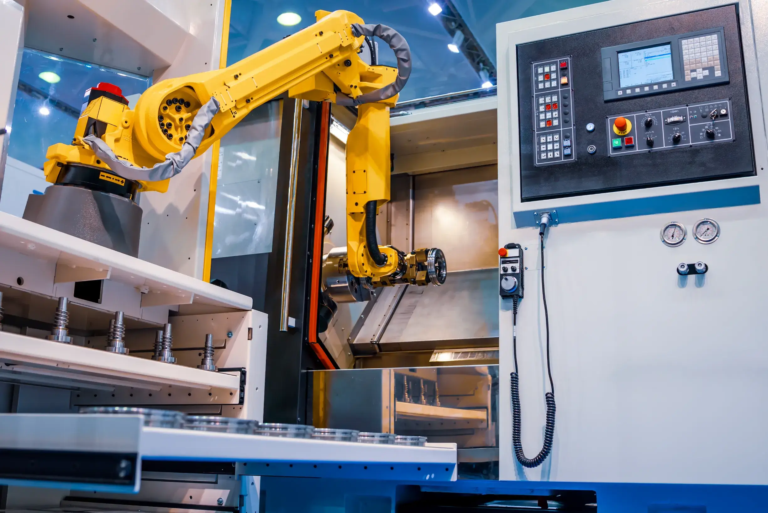
The number of years the PCB will be used also needs to be taken into consideration. When it comes to boards used in industrial automation, repeat repairs, controlled replacements, and maintaining stable revision histories will be required years after the initial order was placed. Ultimately, industrial PCB assembly will be judged based on the risk of operating the board and the level of support provided throughout the life cycle of the product in the field. This will be considered long before the configuration of the components on the board.
Industrial Assembly Differences From Commercial Boards
Commercial electronics frequently have focus placed on compactness, cost effectiveness, and fast turnarounds, whereas industrial assemblies have emphasis placed on workmanship class, material selection, process records, and long-term support as compared to the way in which the components are placed on the board.
When materials are selected for an assembly, they will have designated assembly processes before any component is placed. High-Tg FR-4, Teflon, copper, aluminum, and ceramic materials will all provide different thermal, mechanical, or electrical characteristics as compared to each other. For a durable industrial PCB to maintain its integrity, the material selected must be compatible with the soldering, handling, cleaning, and inspection methods employed during production.
Board Construction Changes That Affect Assembly
The construction of a board will change how the operator of the assembly will handle it. Rigid, flex, and rigid-flex constructions will create different strains on the interconnects, as well as affect the way in which the process protects the interconnects. A rigid control board will be more stable in fixtures, while a flex or rigid-flex assembly will contribute to strain-control and support concerns at the bend areas, around the connector, and for ease of inspection.
The construction of the board will also affect how soldering and inspection are planned, with the same board assembly typically using different fixtures, support pallets, or visual access, based on the panel format or the interconnect geometry.
SMT, Through-Hole Or Mixed Assembly?
Use SMT if compact control logic is required, if fine-pitch packages are utilized, or if the board uses dense sensor electronics. Use through-hole assembly if mechanical or thermal loads will be placed on connectors, terminals, relays, or power parts. Most often, a mixed assembly will be used if an industrial controller is configured with a combination of logic, field wiring, and power interfaces on one PCBA.
The separation of these types of assemblies avoids assembly service providers treating every BOM as the same assembly.
| Assembly type | Use when | Process focus | Inspection focus |
|---|---|---|---|
| SMT | Dense control logic, compact sensors, fine-pitch packages | Solder-paste printing, placement, reflow profile, stencil control | AOI and targeted X-ray for hidden or fine-pitch joints |
| Through-hole | Connectors, relays, terminals, high-power or mechanically loaded parts | Lead forming, insertion, wave or selective soldering, mechanical anchoring | Solder fill, connector support, mechanical fit |
| Mixed assembly | Boards combining logic, field wiring, power interfaces, and serviceable parts | Process sequence, fixture planning, thermal exposure control | Inspection access and stage-based records |
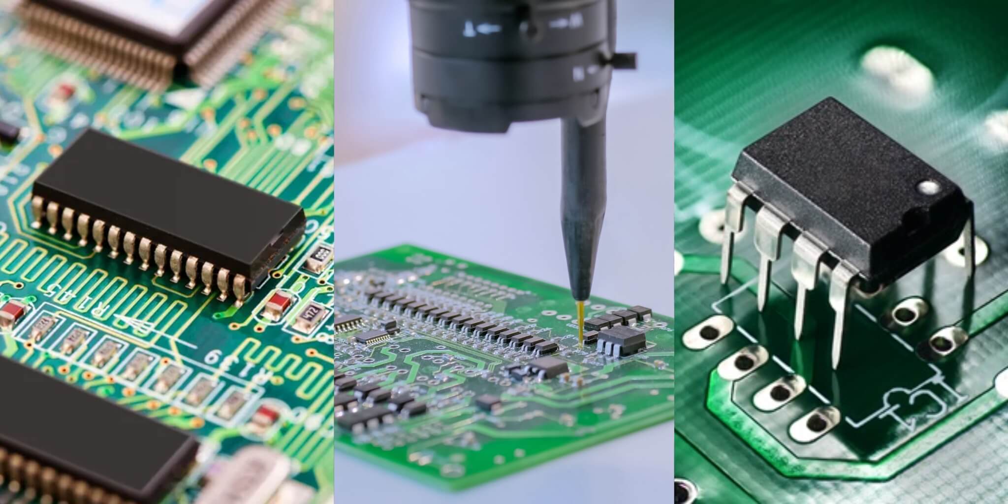
SMT For Dense Control And Sensor Boards
When looking at what type of control boards would work well in an industrial setting, SMT is the most favorable choice. SMT technology enables automated placement and reflow, with higher reliability and consistency on dense layouts compared to manual assembly processes. The parts that fall into this SMT category are BGA and QFN devices using fine-pitch packages, along with 01005 components. The main areas of concern for these assemblies are solder-paste volume, placement accuracy, and reflow profile, where routine process control becomes important for yield.
The ability to identify defects through inspection will continue to play an important role in the production of boards. While AOI will show the defects that are visible during the inspection, hidden joints, such as voids, will not be detected until targeted X-ray inspection occurs, so it is possible that a controller that was shipped with an untested void could subsequently fail from thermal cycles within eighteen months.
Through-Hole For Mechanical And Power Loads
Through-hole components will remain important in many industrial applications, as many of the connections in the field are physical, not only electrical. Connectors, relays, terminals, and power devices will continue to require mechanical anchoring when a technician modifies an installed device by pulling a cable.
Different types of through-hole assembly methods carry different risks associated with the type of component being soldered. Lead mass, connector height, thermal relief, and board support have a direct impact on how well the solder fills the barrel. As an example, connectors that appear to be soldered properly on the schematic could be defective if the wave process does not fully wet tall pins before leaving the assembly line.
Mixed Assembly As The Practical Choice
Many industrial control boards are naturally mixed units, so they often require a variety of methods and materials to be put together. A controller utilizes SMT technology to integrate logic and sensor circuits with the wiring, relay, and power connections routed via through-hole in a manner that protects both and does not affect either process.
The sequencing of events is important. Although SMT is usually run before through-hole, the fixture layout, thermal exposure from wave or selective soldering, and inspection accessibility must be locked prior to the first production run; otherwise, a complete redesign of the fixture would be necessary to accommodate sequencing changes.
Industrial PCB Manufacturing Process From File Check To Delivery
Industrial PCB production starts before the line is loaded. Files must match the revision, materials must be ready, and the build plan has to connect assembly, inspection, and delivery records before the first board is assembled.
- Engineering file check: The alignment of the Gerber files, BOM, placement data, assembly drawings, and project test information against engineering revisions, polarity, footprint, BOM risk, and all other variants produces a controlled set of manufacturing files and engineering findings.
- DFM and material readiness: Once the AVL, approved substitutes, panel constraints, and protection requirements have confirmed the manufacturability, availability, panel design constraints, solder plan, and coating feasibility of the project, they produce the manufacturing plan and material availability.
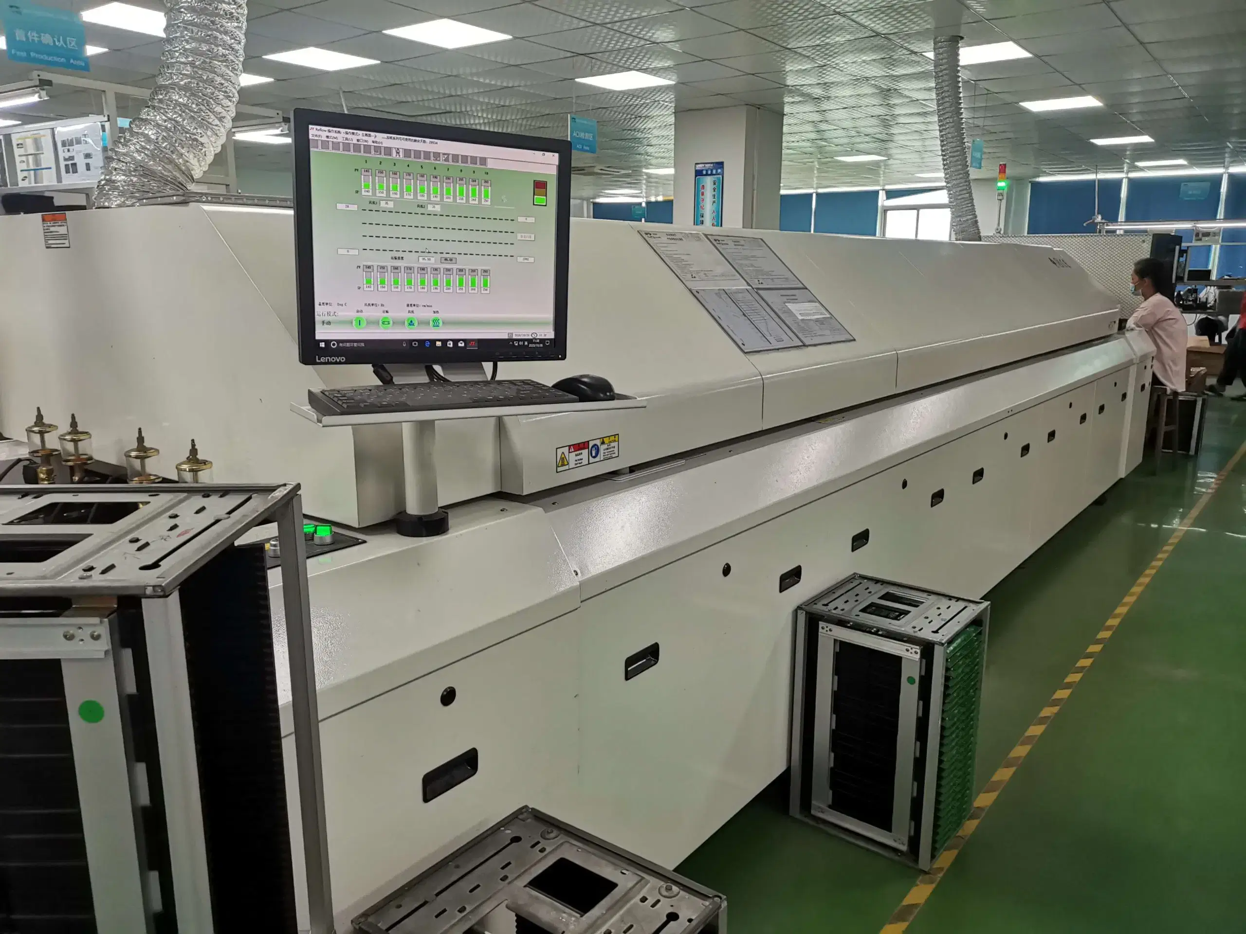
- Assembly: PCB lots, components, stencil, fixtures, and controlled programs support SMT, through-hole, reflow, wave or selective soldering, and cleaning as required, producing assembled PCBAs with batch identity.
- Quality checks: Workmanship criteria and product functions determine visual, AOI, targeted X-ray, and functional confirmation coverage, producing recorded defects and pass-fail results.
- Delivery: Label, packaging, and record requirements connect serial or shipment identity to manufacturing history, producing packed assemblies and production records.
Which Manufacturing Files Start The Process?
Gerber data, BOM, placement files, assembly drawings, and project test criteria will create the full set for manufacturing. The first review of this set will identify any revision mismatch, polarity conflict, footprint problems, component variant confusion, or BOM risk before the issues reach the production line.
When the set of files has been established, this supports sourcing, stencil preparation, placement programming, inspection criteria, and all delivery documents. The file set is used throughout manufacturing.
Material Readiness Before Line Setup
The design intent is connected to the readiness of materials for assembly. The review of materials for assembly includes the following: approved supplier/vendor, approved alternatives, panel size constraints, soldering technique recommendation, material availability, and project requirements.
This review will confirm whether the design for the board is consistent with the assembly plan, whether a substitute component is permitted, and whether the panel will support the handling process from the time the assembly is manufactured until it reaches the customer or field. This check will cover the requirements for protection, such as access to connectors, masking, and repair needs.
Assembly Through Controlled Delivery
Assembly completes the plan and turns it into actual components produced: stencil setup, SMT placement, reflow soldering of components, insertion of through-hole components, wave or selective soldering of components, and required inspection of assembled boards. Throughout the assembly process, a batch identity is attached to each assembly until it reaches a finished condition.
Delivery uses labels, packing slip information, and delivery/documentation history.
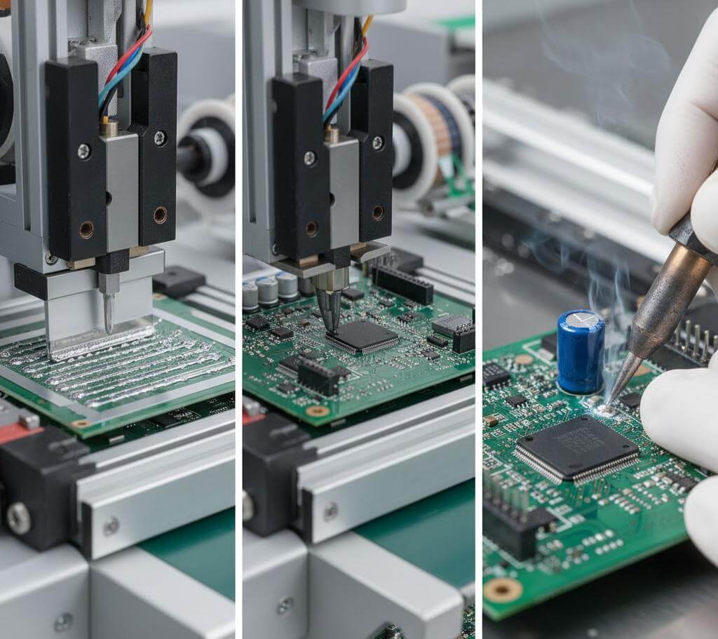
PCB Capability Limits That Change Assembly
The assembly capability of a PCB is dependent on how the PCB is processed, the number of layers in the PCB, the pitch of components on the PCB, the amount of copper on the PCB, and protective coating compatibility with the PCB. Examples include: if a board is very long or wide, has fine-pitch components, has numerous copper layers, or has to be potted, this requires an additional assembly process.
PCB capability limitations can also be evaluated by comparing the values of each of the specifications established above with projects that require assembly handling for components with the following dimensions: PCB assemblies supporting sizes up to 510 x 460 mm, 1-32 layer board support, 0.25 mm pitch BGA, 0.20 mm pitch uBGA, outer copper weight from 0.5-12 oz, inner copper weight from 0.5-6 oz.
| Decision area | SUGA build condition | Representative build data | Assembly impact |
|---|---|---|---|
| Board size | Assembly handling up to 510 x 460 mm (508 x 457 mm / 18 x 20 in) | 18 x 20 in (457 x 508 mm) at the handling ceiling; 18 x 15 in (457 x 381 mm) as a smaller supported panel size | Handling, support, stencil behavior, reflow uniformity, and panel strategy |
| Layer and component complexity | 1-32 layer board-support range; 0.25 mm BGA pitch; 0.20 mm uBGA pitch; 01005 package | More than 20 layers combined with 0.25 mm BGA or 0.20 mm uBGA pitch; 01005 at 0.4 x 0.2 mm | Fine-pitch placement, hidden-joint inspection, and thermal balance |
| Current and laminate behavior | Outer copper 0.5-12 oz; inner copper 0.5-6 oz | 6 oz copper; high-Tg FR-4; Rogers or high-frequency materials | Copper mass and laminate behavior affect heat flow and soldering response |
| Environmental protection | Conformal coating and potting as project-defined protection processes | IP68 potting target; salt exposure; ingress-protection target | Masking, connector access, repairability, cure, and enclosure design |
Which Board Limits Affect Assembly?
Board size variations affect support, stencil behavior, handling, and reflow uniformity — a board nearing the maximum board size of 510×460mm will put significant pressure on fixture span, reflow oven belt width, and, at times, conveyor rails. The number of layers and package pitch will place pressure on placement and inspection differently; for example, a 24-layer board with a 0.25mm BGA usually requires that the stack-up is locked before the stencil design is commenced because late stack-up changes can impede pad registration for the fine-pitch BGA to the point where AOI cannot identify it clearly.

Materials That Change Soldering Response
Both the weight of copper and the laminate behavior impact the transfer of heat and soldering in ways that cannot be identified solely from the BOM. A 6oz copper plane rapidly draws away heat from a solder joint, requiring a modification to the reflow profile, rather than just a thicker stencil; therefore, boards that use the standard reflow profile with a heavy copper pour tend to exhibit cold solder joints precisely where the copper is heaviest.
There is a difference between high-Tg FR-4, Rogers or other high-frequency materials, aluminum, and ceramic. Each of these materials addresses a distinct combination of electrical, thermal, or mechanical requirements; thus, using a specialty material with standard processing will result in a disconnection between the assembly process and the designer’s original goal.
When Does Potting Replace Coating?
Mechanical supports, material selections, methods of cleaning, and protective processes are combined to protect an industrial PCB from factors such as vibration, heat, moisture, corrosion, and electrical noise.
A conformal coating provides protection against both environmental contaminants and moisture while allowing for repair or replacement; potting provides additional encapsulation to a greater extent but also creates issues of heat retention and makes it impossible to reach the failed component.
For potting in an IP68 target environment, both the design of the connector and the design of the cable exit should be considered and approved prior to executing the coating process, in the same way that an enclosure that is fully sealed but has an unsealed cable aperture would not be able to pass an appropriate inspection and would fail the same way as a poorly potted board would.
Exposure to salt and the ingress-protection targets required for an industrial PCB are system-level requirements and should be considered in conjunction with coating line settings; neither is a substitute for the other.
Industrial Assembly Quality Checks
Quality checks include the following for assembled boards:
Visual Workmanship Inspection
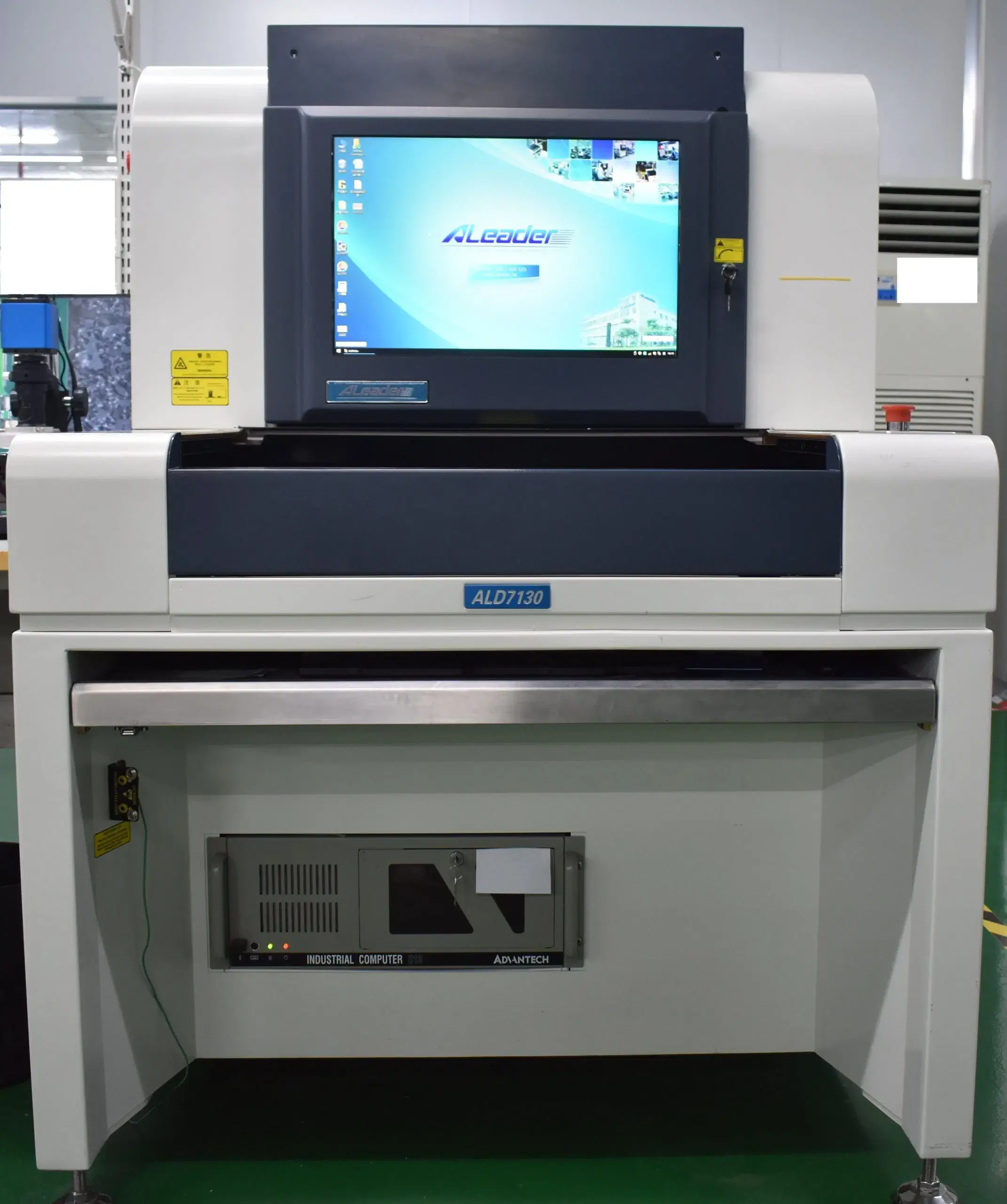
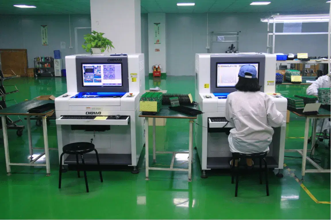
AOI
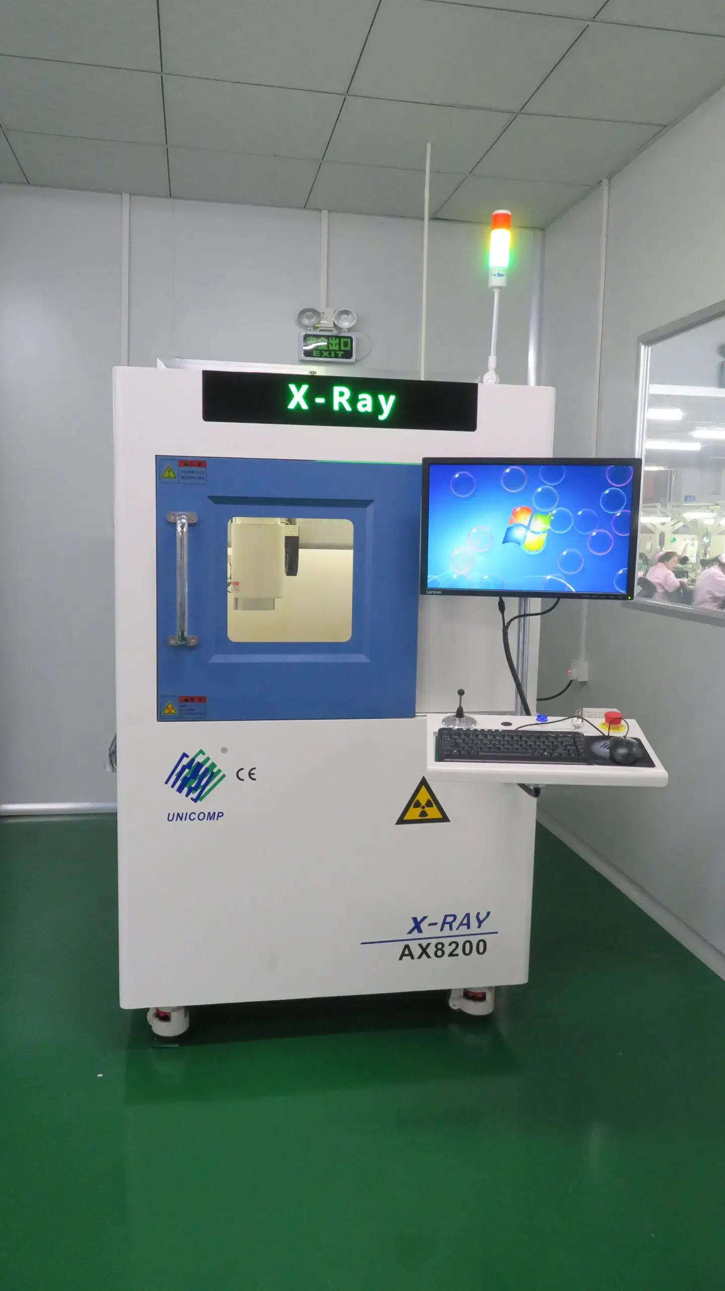
Targeted X-Ray Inspection
Cleaning Verification Testing
FCT
Each method provides information on a specific point in the assembly process and checks the assembly against the IPC-A-610J acceptance criteria for electronic assemblies and the IPC J-STD-001J quality requirements for soldering process and materials.
Where Should Inspection Enter The Process?
Inspection follows the defect a process step creates. Manual checks and optical inspection catch visible workmanship problems. AOI fits placement and solder defects such as missing parts, polarity, tombstoning, and bridging.
BGA, QFN, and other hidden-joint packages use targeted X-ray or AXI when the joint cannot be verified by normal viewing. The point is to match the check to the failure mode instead of treating one inspection method as proof against every risk.
Surface Cleanliness Before Coating
The residual material remaining on a PCB after cleaning is of greater importance in industrial electronics applications than in consumer electronics applications. The ionic content that remains on the surface after the soldering process can have a significant impact on the performance of an industrial PCB, particularly under high-temperature conditions. Adequate cleaning of the PCB assembly in addition to verification of the residual material remaining is essential.
Verification of a PCB assembly as ready for coating or potting links inline aqueous cleaning, drying or moisture checks, masking verification, and surface preparation review to confirm readiness for coating or potting, not to serve as a separate environmental qualification of the PCB assembly process.
Functional Confirmation Before Delivery
A review of all aspects of compliance to project specifications, such as power-up, input/output response, interface performance, calibration, and pass/fail records, is necessary prior to delivery.
Testing for industrial PCB assemblies may or may not use ICT or FCT, depending upon the specific requirements of the assembly design and fixture strategy. The purpose of PCB assembly testing is to confirm that the PCBA will function as specified in the approved documentation.
Component Sourcing, Kitting And Panelization
Having a reliable SMT setup does not happen when the feeder cart arrives at the line. The availability of approved parts and their respective alternative sources, in addition to having the part labels clearly readable, complete panel geometry accurately specified, and excess parts available for continuous operation, will affect whether the construction process flows smoothly or stops due to preventable handling issues related to improperly labeled and positioned materials.
In addition to following controls for sourcing, kitting, and preparing an assembly for SMT, an efficient process linking all three elements together helps an industrial electronics company deliver a quality product to its customers that will not contain shortages of parts, wrong alternatives being used, missing or incorrect part labels, or weak support for the assembled panel.
| Setup item | Setup condition | Why it matters | Line-risk consequence |
|---|---|---|---|
| Part ownership and AVL | Turnkey, consigned, materials management, and obsolete sourcing conditions | Defines responsibility for shortages, substitutes, and lifecycle decisions | Unclear ownership delays substitution and lot approval |
| Reel and cut-tape packaging | Full reels preferred; at least 5 in cut tape | Supports feeder setup and stable component presentation | Short strips interrupt setup or require manual handling |
| Attrition allowance | 2% for ≥0603 passive components; 4% for 0402 and smaller capacitors and resistors | Covers feeder and handling loss during setup | Insufficient quantity can stop a partially completed lot |
| Labels and IC packaging | Proper labels and feeder-ready IC packaging | Preserves identity and machine setup accuracy | Ambiguous labels increase loading and traceability risk |
| Edge clearance and panel size | 0.080 in (2.0 mm) edge clearance; panelization below 3 x 4 in (76 x 102 mm); about 8 x 10 in (203 x 254 mm) panel with 0.25 in (6.4 mm) border | Provides rails, tooling space, fiducials, and handling stability | Weak panel geometry raises handling and depanelization risk |
Who Owns Component Approval?
There are two different responsibilities for turnkey versus consignment parts. When using turnkey parts, the assembly group assumes responsibility for sourcing, handling shortages, and looking for substitutes. When using consignment parts, the customer has supplied a kit; however, this kit must still comply with AVL guidelines. Approved substitute materials, date and lot controls, and a mechanism for the handling of obsolete parts must be established.
This matters when there is a shortage. If there is confusion around who owns or has the authority to approve the substitute, then the lot will sit and wait until both teams agree on who can approve it. The path for how materials management determines the substitute, if needed, should be defined before production begins.
How Should Parts Be Kitted For SMT?
The discipline of kitting parts for SMT is dependent on the packaging of the feeders, as the continuity of the feeders affects the entire setup and not just one item. A cut-tape strip that is less than the minimum length required to be loaded onto a reel holder will slow down the operator and require manual splicing mid-run. A poor splice is one of the common causes of a skipped placement that AOI catches after the fact.
There is also an attrition allowance for the same reason. A kit that matches the BOM exactly, with no allowance for feeder pickup losses, will stop the line an hour before the last board arrives — not because there is a missing part, but because the kit was built with no regard for actual handling losses.
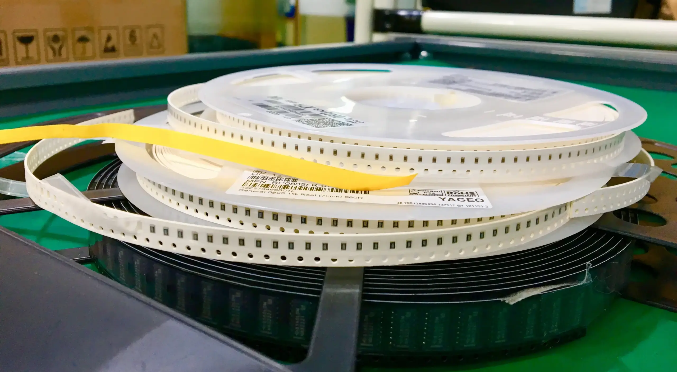
Panel Geometry Before SMT Setup
The design of the panel affects the rails, fiducials, tooling, depanelization of the assembly, and edge-component risk. These issues can surface long before the last board is off the line. Even if a small board passes all electrical tests, it is still possible for it to jam a depanelization router if the panel geometry does not match the tooling. The tool interacts with the geometry of the panel and not the circuit itself.
The format of the panel needs to be in agreement with the fixture, how the parts are placed, and how the panel will be depanelized. All three need to be one decision in the product development process; they do not get signed off separately through different points in the review process.
Industrial PCB Assembly Applications By Equipment Type
Based on the type of equipment being used, the PCB will have different assembly priorities. There are many assembly priorities depending on the type of equipment, but automation boards in the same family must contend with vibration, connector load, noise, and heat. While there are still many stressors for other types of equipment, such as power systems, sensor systems, and harnessed systems, the biggest contributors to stress are attributable to current and thermal cycling.
The main element that determines how these types of assemblies are assembled is driven far beyond just the shape of the PCB. Below, each of the assembly types is broken out further based on equipment type, field stress, assembly priority, and use case.
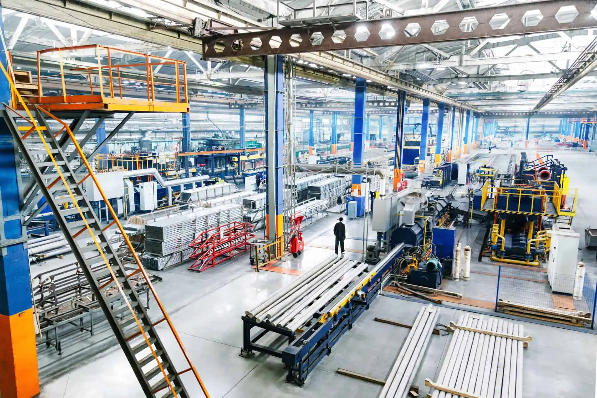
Factory Automation And Motion Control
Motion controllers, I/O boards, and servo-drive controllers all have a close physical relationship to motors, moving equipment, cable bundles, and cabinet wiring. Typically, for motion controllers, the controlling logic will receive field interface stress from vibrations, connector load, noise, and heat prior to damage to the logic.
The manufacturing process for the assembled PCBA must include an assembly plan that supports mixed assembly between a dense control logic section and through-hole interface, uses connector support to accommodate load in the wiring that originates from the field, provides controlled cleaning around high-impedance areas, and ensures that I/O functional checks represent how the PCBA or controller will be utilized in the machine. VFD switching noise can cause interference on unshielded control signal runs that will not be detected until the system is put into commission. This means that a board may have passed all tests completed in the lab, but once placed in proximity to a live drive cabinet, the board may exhibit random encoder counts. Thus, cable dressing, ground stitching, and shield termination need to be part of the assembly plan, not just the schematic.
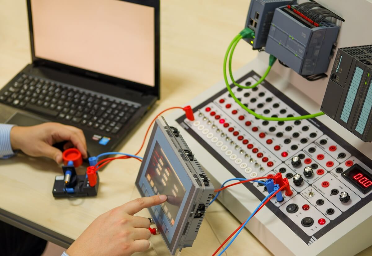
PLC And Industrial Control
PLC is used for integration into industrial control systems. Backplanes, I/O modules, and communication boards suffer from the same challenges when assembling these systems; namely, how to place fine-pitch components while keeping hidden connections, connectors, and revisions serviceable after being released.
Fine-pitch control areas may require targeted hidden-joint inspection, while both serial numbers and revision numbers can assist maintenance teams in determining which revision of a board is currently installed in a cabinet. Thus, a well-designed industrial control build will treat dense electronic designs and field service access as a cohesive system. When using hot-swappable I/O modules, an unforeseen pitfall may not be identified by visual inspection: backplane connectors will be stressed at the same solder joints every time a module is inserted thousands of times during a module’s service life, resulting in the need for mechanical reinforcement or through-hole anchoring of connector footprints, even though the majority of the board may be pure SMT.
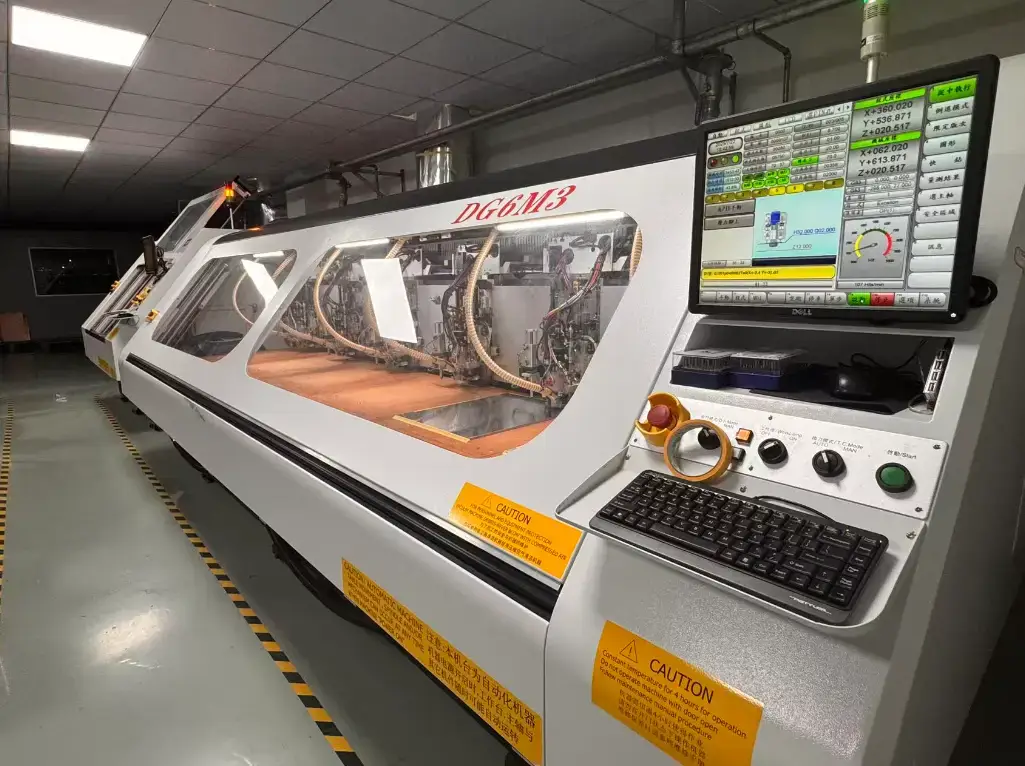
Power And Energy Systems
Power PCBA, charging modules, and inverter controllers place additional burdens on the assembly process by requiring attention to the current path and thermal path when designing the assembly plan. Heavy copper and void risk due to thermal cycling affect the soldering response, thermal balance, and anchoring of power components.
Thermal-conscious soldering of power components, including controlled handling of copper weight, as well as physical support structures for the heat or vibration loads that will be placed on them, is essential when assembling power boards. There are various functional tests that also need to be performed because a power board may visually appear acceptable but will not necessarily perform as expected until current flow, control response, and protection functions have been confirmed. The use of heavy copper pours around power components poses another risk: voids under the high-current pads may go undetected through AOI and a standard X-ray check. These voids may not become evident until the board is under full-load conditions for an extended period, resulting in local heating that is not detected until this time has elapsed. Thermal-aware reflow profiling is as critical as determining stencil thickness for an effective reflow process.
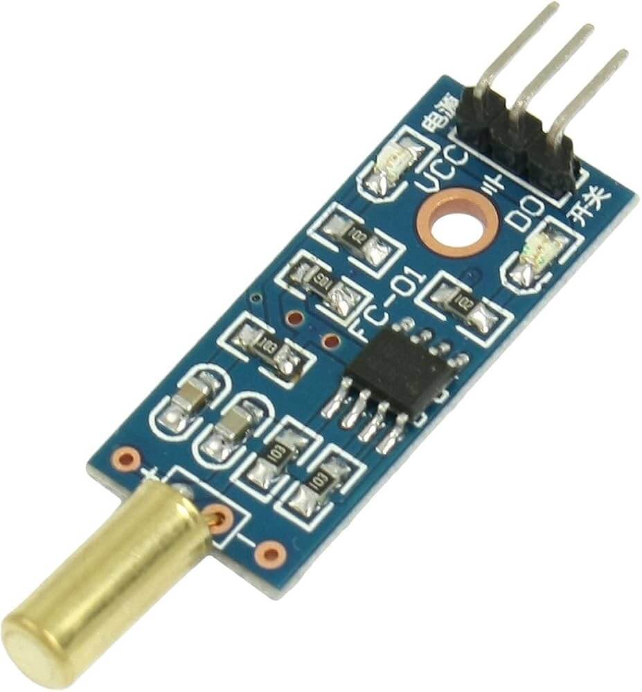
Sensors And Monitoring
Humidity, ionic residue, noise, and calibration stability are concerns when assembling sensor boards, gas detectors, and flow-meter electronics. The presence of very low levels of contamination can create significant problems when the circuit must operate at low signal levels or maintain stable performance over time. Properly controlled cleaning, pre-coating inspections, low-noise assembly requirements, and stable connection interfaces are essential for these types of assemblies.
The main element of an assembly process for sensor boards, gas detectors, and flow-meter electronics is whether the process maintains signal integrity and the surface condition of the boards. While it is good to know whether each component has landed in the correct location, this is not the only consideration when designing an assembly process. Coating selection also matters when creating an assembly for these types of products; for example, some conformal coatings produce off-gassing during the curing process; the calibration for gas detectors will be affected before they are placed in service. A thorough understanding of the chemistry of the coating and how it interacts with the electronic components is required to prevent coating-induced failure modes from occurring after the products have been shipped.

Heavy Machinery And Agricultural Equipment
In the case of heavy equipment for agriculture, the controllers, operator panels, and harnessed PCBAs experience several stressors including moisture, shock, strain on the connector and harness from movement during operation, vibration from the machine frame, and enclosure issues.
The PCBA is often under additional mechanical stress from connector strain, harness movement, operator handling, and vibration from the machine frame. Anchored through-holes, harness strain relief, conformal coating, and final assembly inspection also affect component placement decisions. As an example, a working PCBA may fail after it has been sent to the field or after a run-in period due to improper fit of the enclosure, cable pull on connectors, or improper connector positioning that puts a mechanical strain on the solder joint. As the vibration is transmitted through the machine frame, it tends to gradually push connector backs out rather than all at once; a board may have passed functional testing at the time of handover but developed intermittent faults several months later. Using locking connectors, thread-locking on backshells, and strain relief at the harness exit during assembly may help minimize intermittent faults after a field complaint.
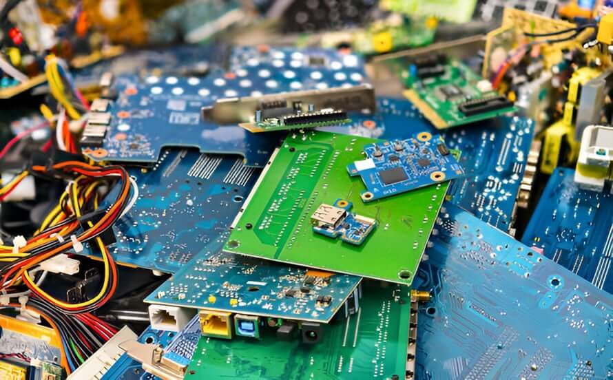
Commercial Industrial Equipment
Some examples of products in the commercial industrial equipment category are printers, smart-label systems, lighting controls, and switchgear controllers. These products are frequently built in mixed volume and with multiple variations, making it less about one form of stress throughout the assembly process but more about sourcing, wear at the interface between components, lifecycle, and repeatability.
Maintaining the continuity of supply, a mixed-technology assembly process, and a repeatable program will help keep future assemblies aligned with approved versions of manufactured products. For these products, the most meaningful benchmark will be whether the same PCBA can be manufactured again with the same materials and interface durability and also with controlled variation. Practical risks for mixed-variant builds are in the kitting process, because it is common for a mixed BOM variant to have all but one connector or resistor value identical. If an assembler loses track of the BOM variants, to the point of not knowing which one they are building, the chance of mis-kitting exists.
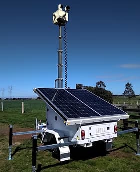
Oil, Gas, Solar And Security
Outdoor controllers, monitor or inverter auxiliary PCBAs, and security electronic assemblies must withstand moisture, corrosion, and temperature swings; both coating and potting type selection must consider PCBA cleanliness when sealed-interface planning, connector masking, enclosure design, and cable exits are carried out. Control of contamination matters before protection, and potting selections must also consider thermal heat dissipation and repair access. A PCBA is only one component of the total protection system; however, the assembly process dictates whether the board is properly prepared for the protection process.
Potting of outdoor assemblies has a slow failure pattern due to the natural degradation of some potting materials by UV rays and thermal cycling over years of sun exposure. Consider the expected number of years a compound will be exposed to direct sunlight in conjunction with the rating provided by the manufacturer when using potting compounds.

Rail Transit And Field Infrastructure
Control boards and communication boards for rail transit and field infrastructure are evaluated based on their longevity as well as their operational performance in terms of vibrations associated with continued use. Since these systems will typically be in service over several years, durable interconnects and repeatable inspections are just as important as the initial build.
Retained production history will support both maintenance and repeat orders, and provide reference for batch review when a field issue arises. The assembly plan provides durability for service, while the record plan allows for traceability to support long-life infrastructure. A mechanical joint on the board will typically be the weakest point from years of exposure to vibration on rail equipment, rather than an electrical one, and connector anchors and strain relief need to be designed with the same consideration as the circuit design itself.
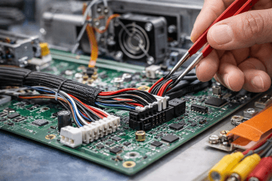
Cable, Harness And Box Integration
The addition of harnesses and enclosures to the PCBA adds routing, insulation, strain relief, and final assembly information to the build decision. The identity of the board with harness and connector control, as well as final assembly verification, provides assurance that the board will survive the installation process, and not just when it is on the bench.
The connector placement, insulation routing, cable bending, and enclosure clearance will determine whether a correct board is built to survive field use, which is why the cable, harness, and box integration process is integrated during assembly planning, rather than being signed off separately once the assembly is complete. The failure that is easily overlooked in the review process is at the strain-relief point: a connector housing may crack months after installation if the potting or over-molding does not extend far enough before the area where bending occurs. Such a defect is generally not discovered until the assembly has already been installed and is experiencing load during field use.
Across the nine families of equipment, the assembly priority changes, but the need for sourcing, control, and inspection increases in view of the dominant stress. Sourcing, SMT, through-holes, protective processing, and inspection for SUGA have the same range of capabilities as those of other manufacturers that split the work across multiple partners.
Industrial PCB Production From Prototype To Repeat Builds
Prototypes help demonstrate function and manufacturability, whereas NPI provides stability of materials and an ECO process for locking in specifications. Production scaling defines the materials, the supply chain, and the inspection requirements for a production part, and each step will carry different timing and evidence requirements.
As the risk of industrial PCB production moves from exploratory to reliability, prototype construction allows for controlled learning, while repeated production requires assurance of a stable supply, established setting parameters, and retained documentation.
| Stage | Primary goal | Revision control | Material & inspection focus | Production records | Production timing |
|---|---|---|---|---|---|
| Prototype | Validate function, fit, and manufacturability | High change tolerance; controlled learning allowed | Often partial, substitute-sensitive, or customer-supplied; visible defects and required functional checks | Basic revision and build notes | 24h/7-day figures depend on file, material, and process readiness |
| NPI / pilot | Close assembly issues and stabilize ECOs | Changes are documented and closed | AVL, substitutes, panel and process plan reviewed; deeper inspection where prototype risk appeared | Revision, issue, defect, and correction records | Timing depends on BOM, process depth, and material readiness |
| High-mix low-volume | Build multiple variants with controlled identity | Variant control required | Supply continuity, labeling, and variant-specific inspection matter | Lot and variant traceability | High-mix timing follows variant count, material status, and inspection depth |
| Repeat production | Maintain stable output and repeatability | ECO requires formal control | Mature supply, approved process plan, repeatable inspection, functional confirmation | Full production record package | Separate assembly-only and procurement-plus-assembly timing |
Prototype Assembly For Design Validation
Prototyping allows for design, process, and sourcing issues to be identified before the production stage. Prototype assembly validates the product’s form, fit, and function, as well as its manufacturability while allowing for controlled deviations, rework learning, and issue discovery.
The same timeline for 24-hour and 7-day promises would generally apply here, although file readiness, material status, and process depth must be confirmed in advance. Speeding up the prototype turn on an unconfirmed BOM just moves the delay to NPI.
Pilot Change Lock Before Production
The documents generated through the NPI process are the final records of prototypes, materials, process settings, and ECOs prior to full-scale production. Misconceptions regarding ECO decisions and material readiness will cause the same issues to redevelop later in the manufacturing of the same parts or systems as part of future production lots.
Every variation of a product needs to be recorded as part of the final revision control system after a pilot run so that history is preserved and accurate, thereby providing an accurate understanding of what has actually changed, what issues closed, what potential risks still exist, and what criteria must be checked for the final release.
Scaling High-Mix Work Into Repeat Production
With the wide variation in engineering, manufacturing, and inspection standards for high-mix low-volume assembly operations, the information to control the supply of parts and materials, manufacturing identity, and inspection criteria matters when several different versions are in production simultaneously.
Repeat production manufacturing processes limit opportunities for informal adjustments and outside quality checks for engineering and tooling. This limitation has created common industry measures such as 2-4 days for urgent request, 5 days assembly-only, and 10-15 days for procurement plus assembly when calculating time to manufacture a high-mix low-volume assembly based on BOM depth, material readiness, and process scope.
Traceability And Production Records
Traceability uses material batch numbers, material types, where they are used throughout the manufacturing process, inspection results, protection record numbers, label serial numbers, and all shipping lot numbers associated with production for each product. By having a record chain for all shipping, the quality or purchasing department can trace back the complete history of an assembly, from the material lot to all steps involved in production to the end of the assembly.
This information provides access to repeat orders, ECO analysis, field maintenance analysis, isolation of batch failures, and future failure analysis without requiring the team to reconstruct the entire history of production from memory.
How Are Material Lots Linked To Serials?
Material lot identification starts with the BOM associated with the assembly. The manufacturer AVL, manufacturer part number, approved substitute parts, PCB lot, and component part lot are connected to the assembly. All of these records shall remain connected with the assembled serial number label and the shipment lot of that assembly.
PCB lot identification is also important. The PCB fabricator lot number, PCB revision, surface finish, and panel identity connect the production history of the assembly to the bare-board lot used for that assembly. Total traceability gives the production team the ability to isolate specific lots of a given product, as well as to review an ECO or repeat manufacturing without having to guess what component parts were used in the assembly.
Process Records From SMT To Final Assembly
Manufacturing history is directly linked to defects or deviations from the process. The SMT batch, through-hole batch, program revision of each PCB, the associated process step, and the associated defect or deviation record identify the point at which a defect or deviation entered the process.
Inspection records typically include AOI results, targeted X-ray results, ICT, or functional test results if required by the program. Final inspection records include the type of coating material used, the area of the assembly that has been protected, the cure records for potting material used, the identity of the wiring harnesses used, and the identity of the enclosures used to protect the assemblies. SUGA tracks more than 200 process parameters across the line for process control, but those parameters are not a substitute for customer-approved inspection documentation specific to each individual project.
The Production Record Package
The production record package consists of revision data, lot number and date of production, inspection results, serialized product, packaging information, and shipping information. It provides the base for repeat orders, ECOs, field maintenance, and failure analysis.
Under ISO 9001:2015 and RoHS compliance, the production records contain the quality evidence required per the relevant product documentation. SUGA will retain the production records for a period of 15 years, provided the production records can link an item that was shipped back to the material identity, inspection history, protection records, serial labels, packaging configuration, shipment lot, and date of shipping when requested.
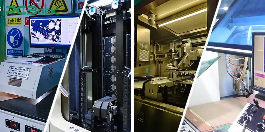
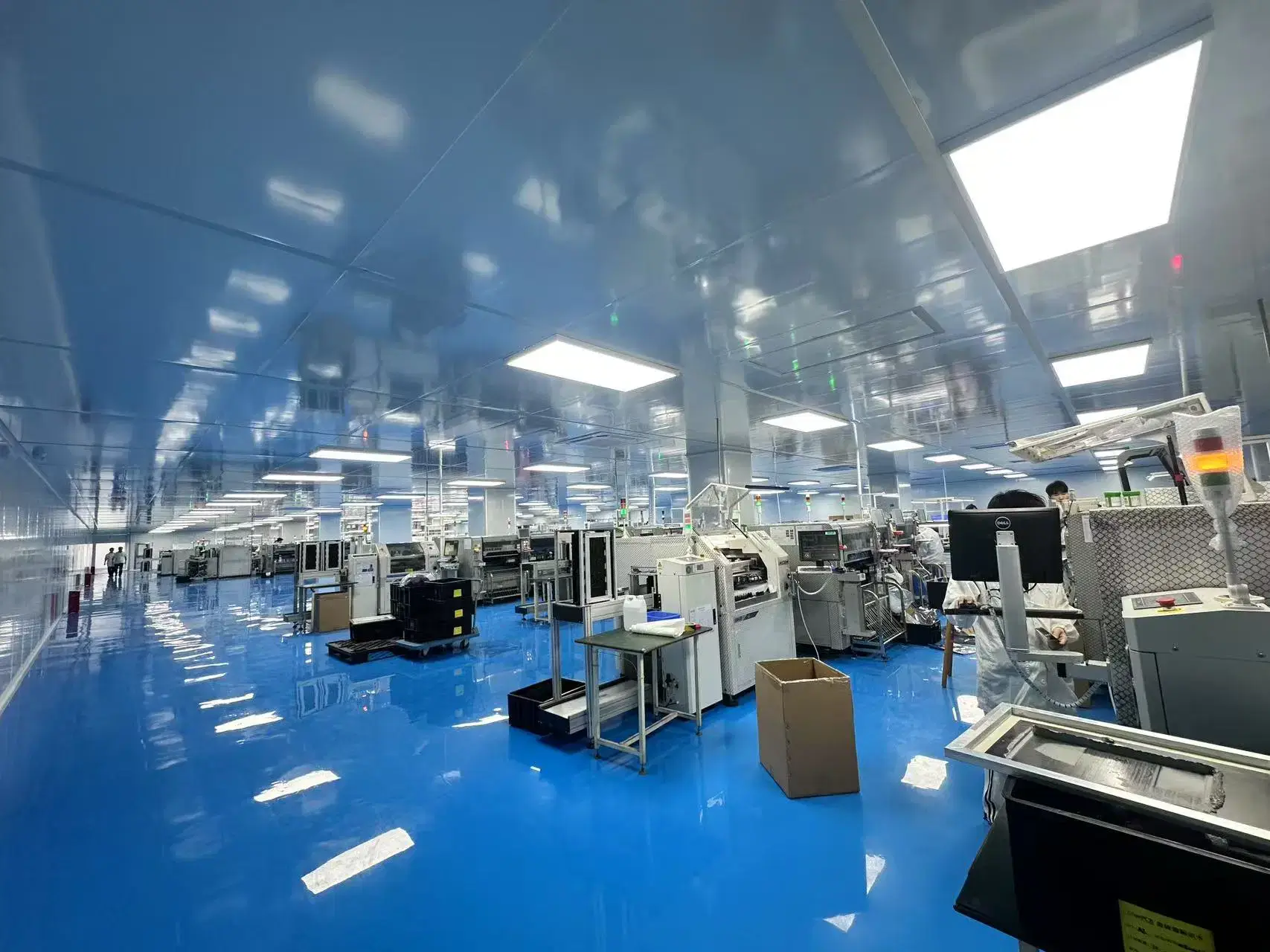
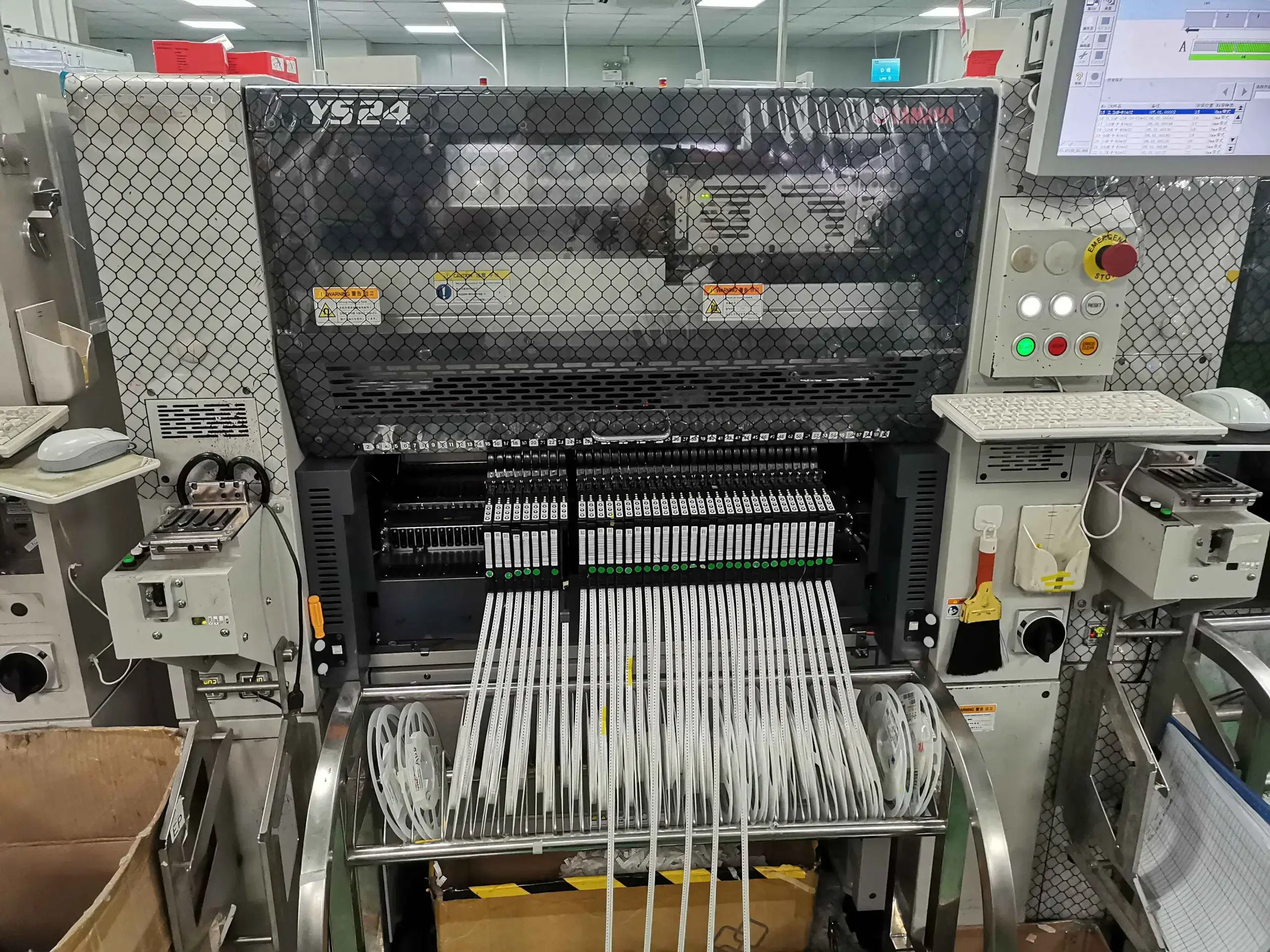
Our PCB Factory Gallery
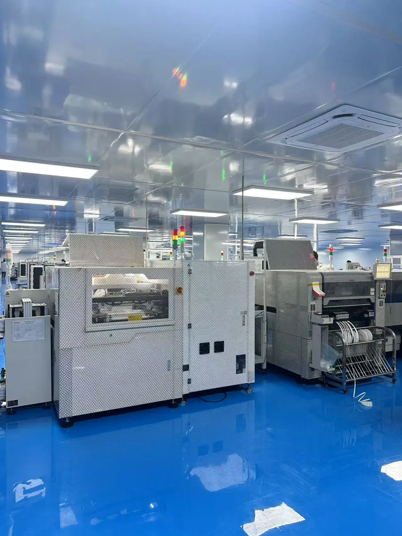
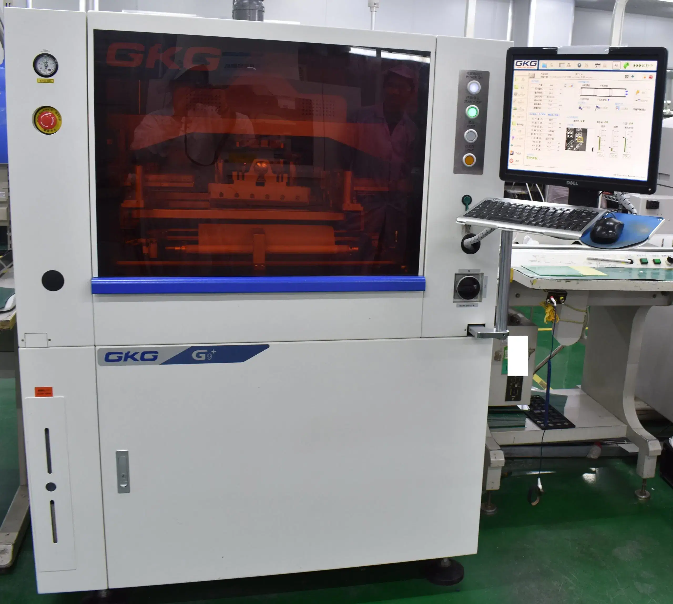
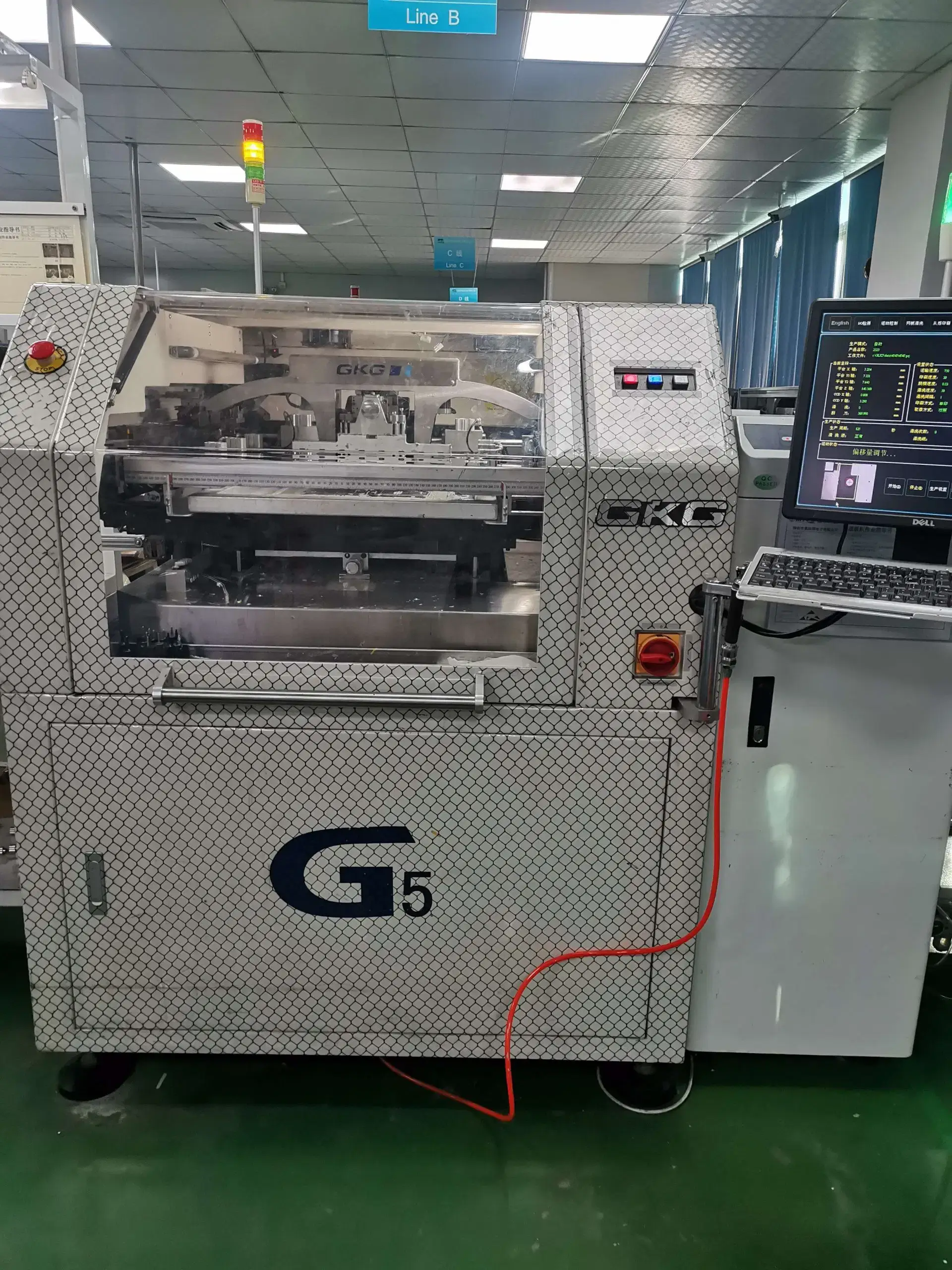
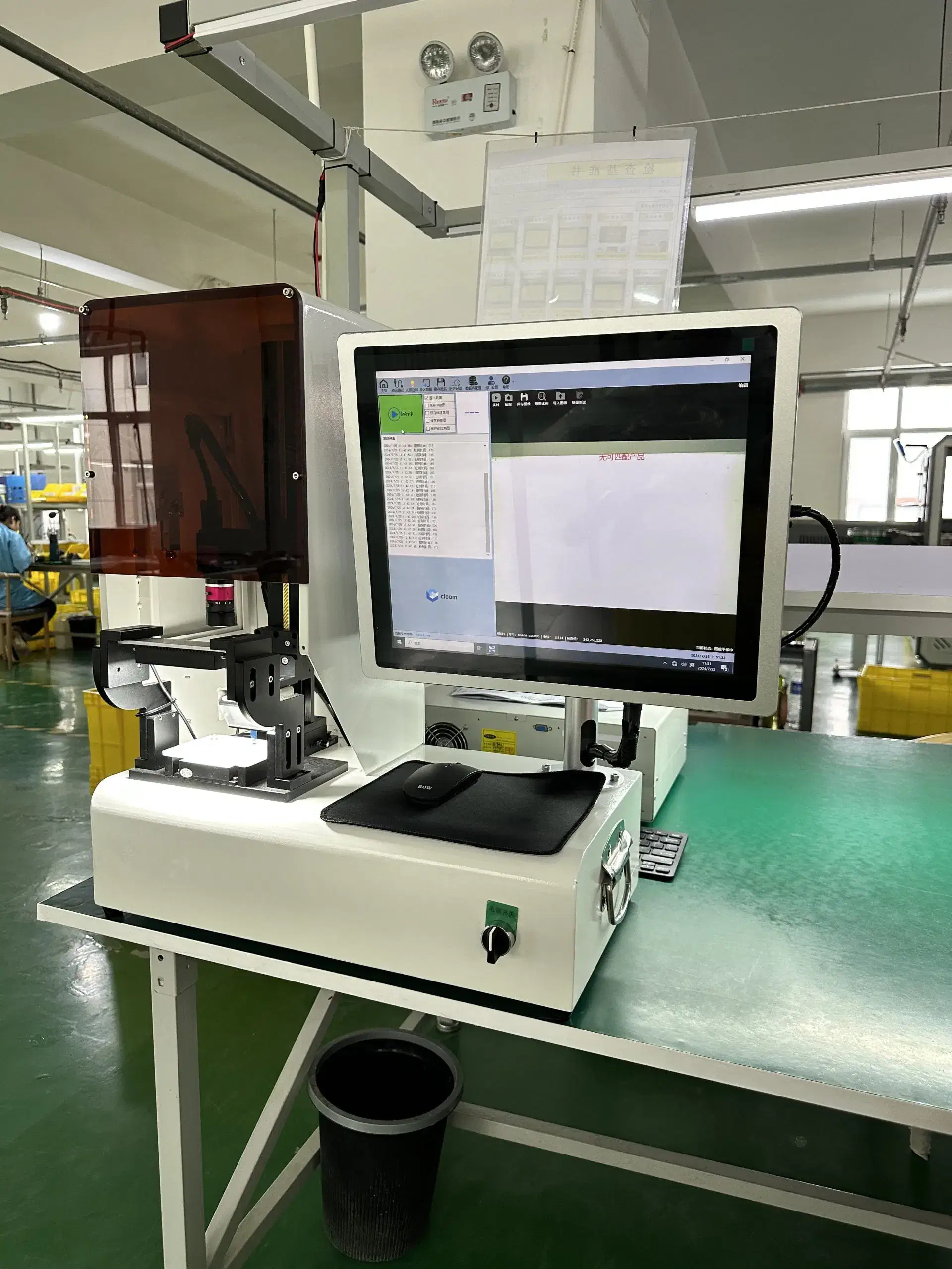
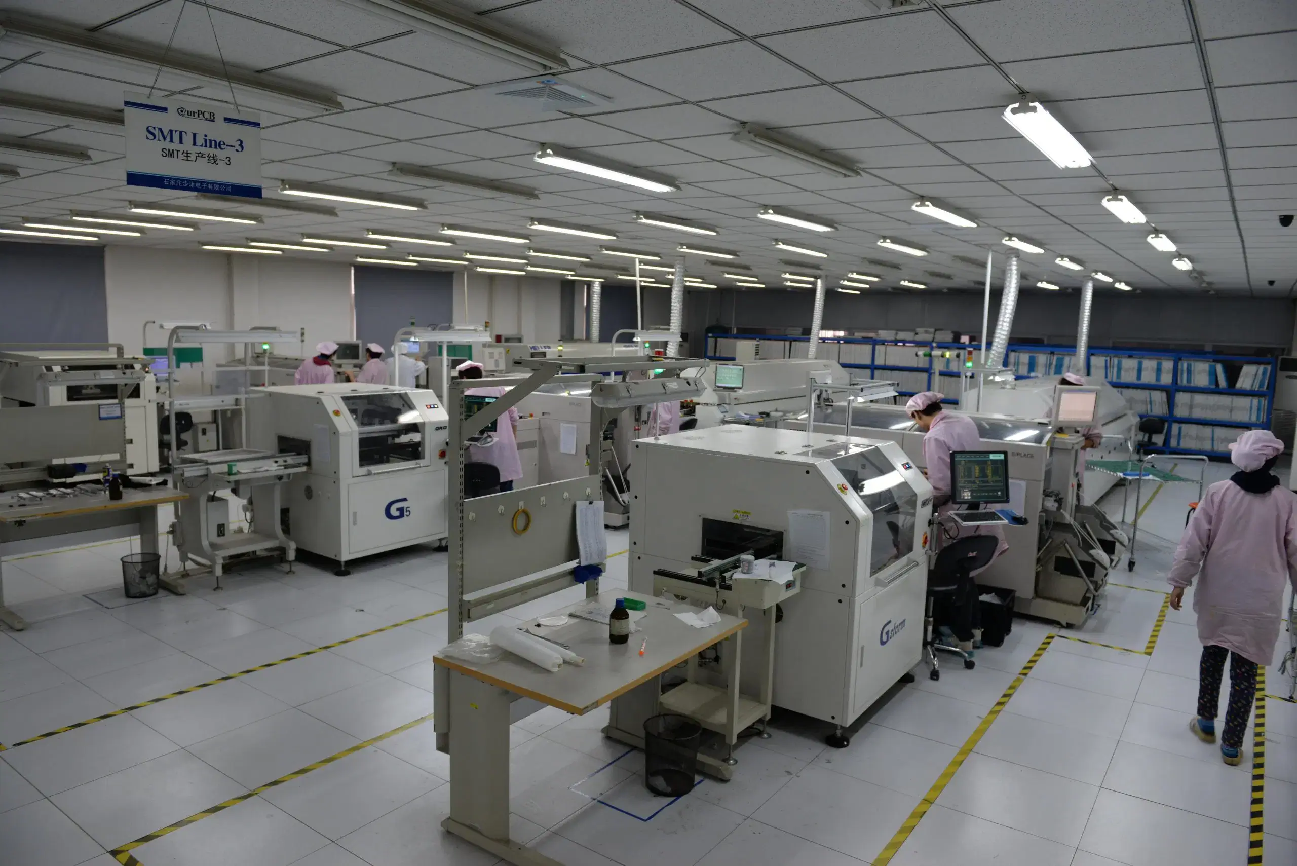
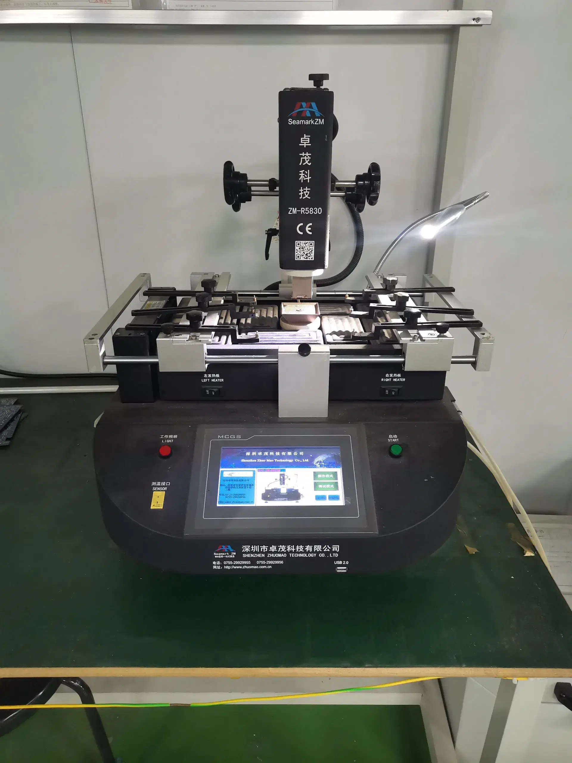
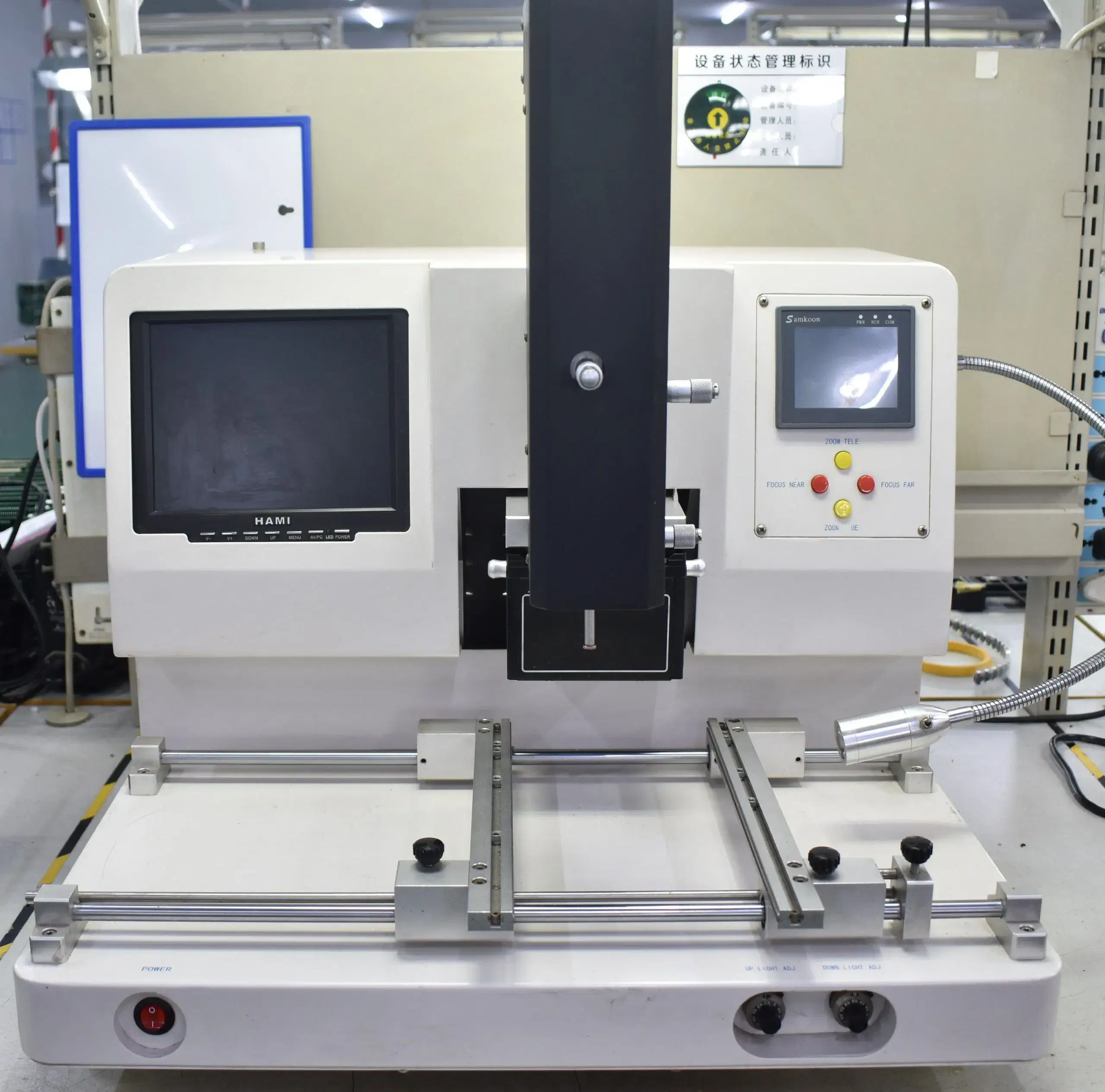
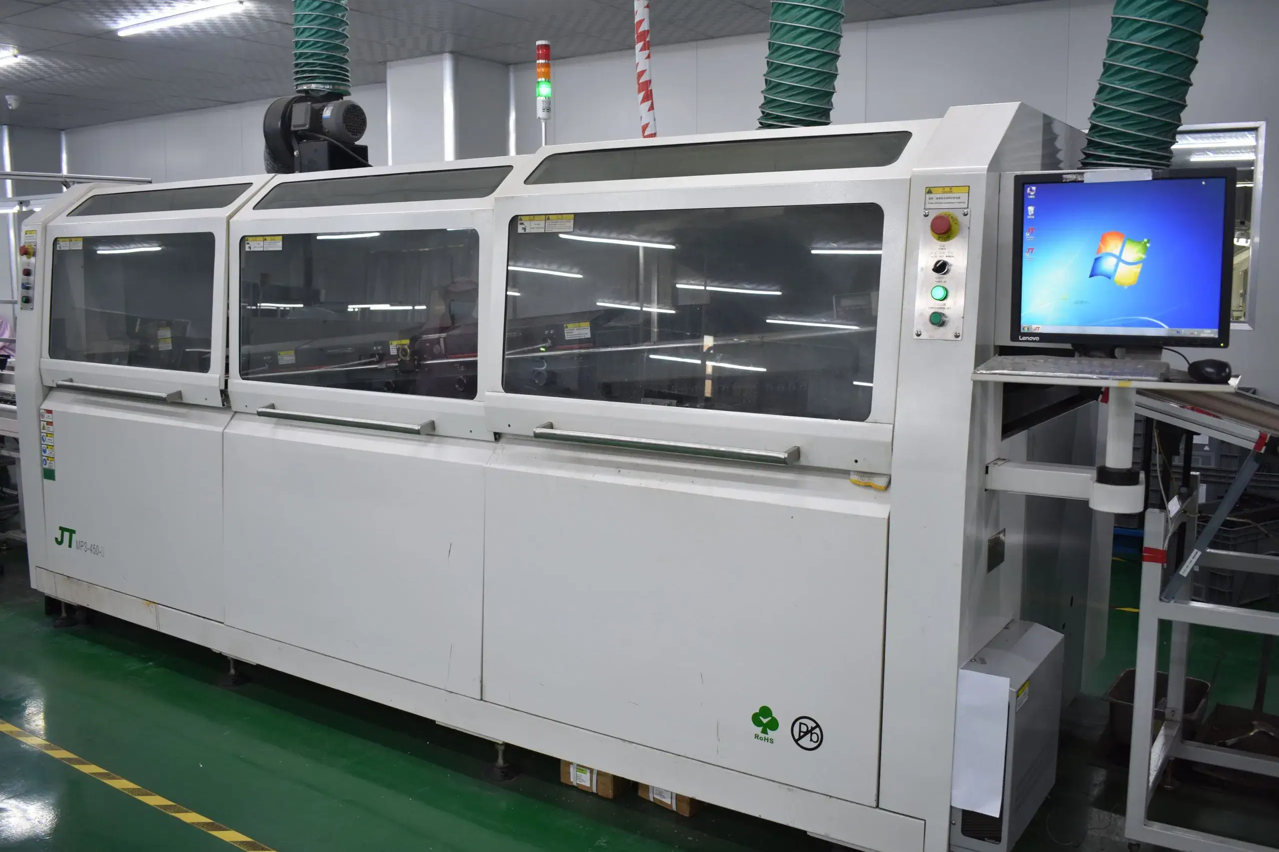
FAQ
Yes, many industrial PCB assemblies contain SMT on more densely packed areas, such as logic and sensors, while using through-hole components on connectors, relays, and high-energy electrical interfaces. The mixed process will affect the soldering sequence, jigs used, access for inspection, and the methods used for record keeping.
Conformal coating and potting are methods of protection used for industrial PCB assemblies when long-term operation is threatened by contamination, moisture, corrosion, vibration, or exposure to the enclosure. The decision of which is preferred will depend on the requirement for masking, connectors, cure, heat paths, and enclosure type.
Obsolete components should go through lifecycle review, approval by an AVL, approved substitute development, controlled redesign if necessary, and documented change history. The review process must be completed before production setup to avoid shortages causing assembly line stoppage or unapproved revision changes.
Production records link the BOM and AVL as well as PCB and component lot numbers, SMT/THT history, inspection results, protection record, serial labels, and shipment batch. This link helps production teams replicate a build, isolate a specified lot, review an ECO, or investigate any item returned from the field.