Upload BOM & Gerber
-
Mobile: +86 13312967631
-
Email: sales@sugaintl.com

Automotive PCB Assembly Manufacturer
From Prototype to Production, with material planning, mixed assembly, inspection, testing, traceability and controlled release.
−40°C To >125°C
10–15 Year Service Life
10 oz Heavy Copper
1.8/1.8 mil Inner Trace/Space
What Is Automotive PCB Assembly?
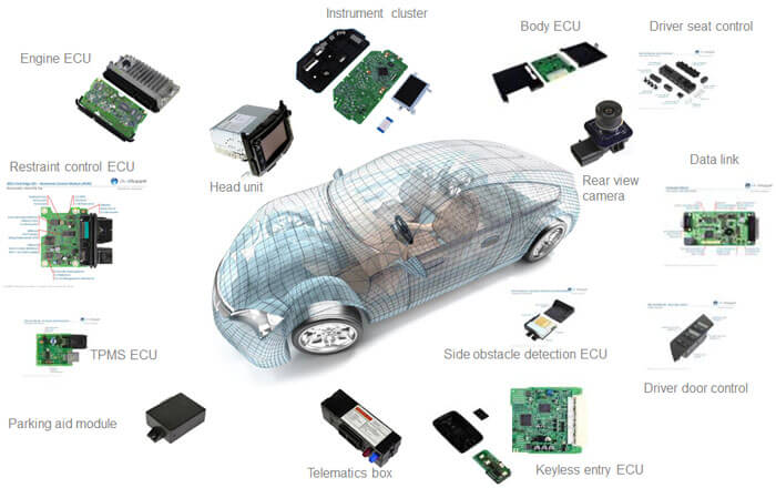
Automotive PCB Assembly covers the process from released PCB and component data to a populated, soldered, inspected, tested, and traceable assembly for an automotive electronic device. These steps include material planning, component sourcing, SMT and THT assembly, conformal coating, programming, testing of the assembled unit, and records of the production process.
Automotive electronics may be expected to be in use for 10 to 15 years, and they may be exposed to temperature extremes from −40 °C to above 125 °C. The long service life and temperature exposure mean automotive products must comply with specific automotive program requirements for components, assembly process, inspection, and testing records. These requirements do not guarantee that an automotive electronic device will function under every temperature extreme, or that its life exceeds the requirements for the parts it contains.
Automotive-Grade Assembly Requirements
Automotive PCB Assembly requirements are defined by controls established around the physical build of a product. The customer must release the BOM to the relevant parties, and the BOM must identify all approved components and approved alternate parts. The manufacturing or assembly process for each product must define soldering, inspection, testing, coating, programming, and review steps using qualified components. The unit must be identified with the associated inspection, test, rework, and change records for that product.
The assembly process or equipment used to manufacture a completed automotive electronic device is not a guarantee that the assembled unit will comply with the required specifications for the customer and the automotive program. The design of the board, solder joints, connections, coatings, and enclosures will all require review to ensure that the assembled unit meets the component and automotive program requirements.
Turnkey and Consigned Assembly
The terms "turnkey" and "consigned" refer to material responsibility in the assembly process for manufactured automotive electronic units. The turnkey assembly process gives suppliers responsibility for sourcing materials and managing assembly, while the consigned assembly process relies on the customer to provide components. In either case, rules should be established for material ownership, part liability, and responsibility for assembly process inspection. A hybrid approach may be used, where ownership is split between the supplier and customer based on the assembly process and part number.
Which Automotive PCB Technology Matches Each System?
Automotive PCBA technology must match the electrical load, thermal path, signal characteristics, package density, and operating environment. In addition to these criteria, the maximum number of layers or copper thickness alone cannot determine whether a manufacturing process can support PCB production, and the materials used to manufacture the PCB must be compatible with the required process. The choice of board technology limits the PCB manufacturing processes, as well as reflow profiles, tooling, and inspection access. When PCB fabrication and assembly are released under one package, the board-level technology choice directly affects the assembly methods used to manufacture those PCBAs; therefore, the manufacturing and assembly specifications cannot be treated as separate decisions.
| Automotive system | Design condition | Relevant capability | What to check |
|---|---|---|---|
| EV powertrain and BMS | High current and thermal dissipation | Heavy-copper PCB up to 10 oz and metal-core options | Stack-up, finished-copper definition, layer position, current/thermal assumptions, coupon or test proof |
| ADAS and sensors | High-speed or RF signal integrity, including 77 GHz radar context | HDI and high-frequency materials such as Rogers or PTFE | Material designation, impedance plan, RF verification method |
| ECU and control modules | Dense, compact and reliability-sensitive packaging | Rigid-flex and multilayer construction; up to 32 layers for ECU/control modules, with up to 64 layers retained as a broader multilayer capability pool | Stack-up review, assembly-process compatibility, flex constraints, via structure and inspection access |
| Lighting and body electronics | Mixed connectors, power devices and control ICs | SMT, THT and mixed-technology assembly | Placement list, selective/wave solder plan, electrical test concept |
| Infotainment and connectivity | High-speed digital interfaces and compact layout | Controlled impedance, HDI and fine-pitch assembly | Stack-up, loss target, X-ray/AOI coverage and functional test plan |
BMS and Power Electronics
Heavy-copper formation relies on the exact definition of the copper used in high-current paths. The success of a heavy-copper design in the context of BMS and powertrains depends on copper integrity and the following: layer stackup, trace geometry, current, temperature rise caused by current, and heat transfer through the device. The maximum thickness of copper defined as capable based on the application is 1000 μm and is available only for special applications, such as busbars and coin-embedded products; the typical claim of 1000 μm copper as a finished product is not supported by the majority of printed circuit boards and must be verified for a specific board type before quoting this capability.
The following may be used to support heat management of the BMS or powertrain design: related materials with a Tg above 170 °C (high-Tg FR-4), metal-core materials, intermediate means for heat transfer by thermal vias or copper thermal mass, and local hot spots managed by copper thermal mass. A separate isolation strategy must be created, and the engineering requirements must include an explicit definition of finished copper, base copper, creepage, clearance, and the path into the enclosure.
ADAS and Sensor Electronics
The 77 GHz radar board operates as an RF system and requires that the identified material, dielectric characteristics, controlled impedance, routing geometry, shielding, and connector transitions all have the same target operating condition, not a generic material name or a manufacturer's name. The operating target must drive the selection of materials, such as Rogers, PTFE, and other high-frequency materials.
Camera assemblies include fine-pitch packages with very limited access for inspection. HDI packaging may provide escape room, while X-ray for internal inspection and AOI for external inspection will need to consider very different groups of defect types. The inspection plan must reflect the actual package geometry and not be listed on a general equipment list.
ECU and Control Modules
ECU packaging may have high multilayer density, rigid-flex sections, heavy connectors and components, and harsh mechanical environments.
While the qualified build of an ECU will be based on the completed build and will not be determined solely by the number of layers in the board, the entirety of the build must be used to determine the qualified build. Inner trace and space can reach 1.8mil/1.8mil, while outer trace and space can reach 2mil/2mil. The available feature pool also includes a 3mil laser hole, a 0.1mm mechanical hole, and a maximum 40:1 aspect ratio — the 40:1 figure applies to high-layer-count backplane-style constructions and is not a default assumption for every ECU stack-up. Copper distribution, hole-wall plating uniformity, and reliability requirements narrow which of these features can combine on one board.
SMT, THT, or Mixed Assembly?
Automotive assemblies often place fine-pitch ICs beside relays, connectors, and power devices. Reflow handles the SMT population; selective or wave soldering may follow for through-hole parts. Mixed technology therefore needs compatible thermal exposure, tooling clearance, barrel-fill criteria, and inspection access.
Process order matters. A connector added after reflow can block X-ray access or require localized heating near a sensitive package.
Materials That Change Assembly Behavior
Rigid, flex, rigid-flex, metal-core, heavy-copper, HDI, and high-frequency constructions solve different problems. FR4, Arlon, Taconic, Nelco, Isola, halogen-free materials, Rogers, PTFE, and PI form a usable material pool. Microvias, blind and buried vias, via-in-via, via-in-pad, and stacked vias expand the interconnect options.
To choose component finish options, storage conditions, assembly methods, and acceptance techniques correctly, you must match them up with the requirements the PCBA design, component mix, and acceptance criteria will exhibit. OSP is best suited to use in very high-volume SMT-only builds, while ENIG or ENEPIG are preferable for PCBAs that have fine-pitch BGA or wire-bond pads and require a flat, long-shelf-life surface.
How Does the Automotive PCB Assembly Process Work?
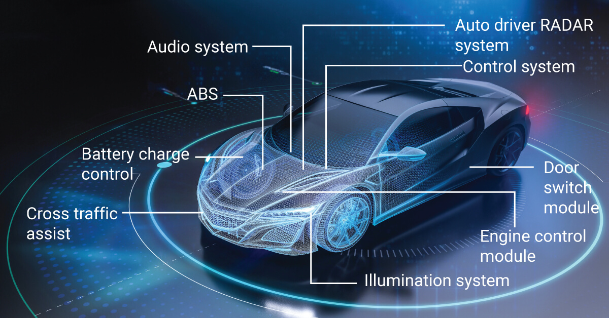
The PCBA process for the automotive industry uses a systematic approach to convert manufactured design files into manufactured hardware through the following succession steps: engineering review of the manufacturing files, board and component preparation, placement of parts on the board, soldering of parts, inspection of finished assembly, testing of finished assembly, optional coating, identification, and release. The exact sequence of steps will vary based on board design, the type of components used to make the board, and specific acceptance requirements for finished assemblies.
- Review manufacturing files and select materials required to complete the assembly. The build requirements are established from the manufacturing files (Gerber or ODB++), BOM, board drawings, and test intent.
- Fabricate circuit pattern based upon the approved stack-up.
- Drill and plate vias and holes identified by the via and hole designs.
- Prepare components for placing SMT parts based on the released BOM and feeder data.
- Solder all SMT and through-hole components based upon the approved process and tools.
- Inspect, test, and apply coatings to finished assemblies per the defined acceptance criteria.
- Ship all assemblies that pass inspection and test and provide product identification and records.
Engineering Review and Material Planning
The engineering review and material planning begins before materials are purchased. All fabrication data, stack-up, BOM, centroid data, assembly drawings, coating references, programming files, and test intent details must have the same revision level. Questions left open are recorded using assumptions that determine pricing, material selection, tooling, and time frame.
Also noted for the BOM are the approved manufacturer part numbers, DNI status, alternate rules, date-code constraints, and the sourcing ownership for each BOM part. If all of these assumptions are resolved before placing an order, it will help eliminate the possibility that a late substitution could change the electrical, thermal, or qualification requirements for a product.
For quoting purposes the following information is the most important:
- Gerber or ODB++ fabrication data.
- BOM with approved manufacturer part numbers and alternate manufacturers.
- Centroid data and assembly drawings.
- Coating, programming, or labelling notes if required.
- Electrical, functional, or inspection requirements.
- Quantity, target acceptance class, and delivery expectation.
PCB Fabrication and Component Preparation
The production of bare boards is based on the approved materials, layer stack-up, copper, via, finish, and dimensional measurements. During incoming verification, the board and components will be inspected against the released build requirements. Lot and revision identification starts at this manufacturing process step, not after assembly completion.
Component preparation includes kitting, polarity checking, moisture-sensitive handling, baking if required, making feeders, and confirming consigned quantities. Although both the board and kit may be correct, they could belong to different revisions.
Soldering Process for Mixed Assemblies
Typically, mixed assemblies follow the process of placement of surface mount components, reflow, automated optical inspection, through-hole component insertion, selective or wave soldering, X-ray, and electrical or functional testing. However, the actual assembly sequence is determined by many factors, including package geometry, thermal sensitivity, the weight added by connectors, board support, and inspection access.
The process plan should identify stencil openings, solder-paste requirements, profiles, tooling, polarity checks, barrel-fill expectations, and any manual operations that may be required. For assembly operators, all of the above information should be in a released set of instructions, rather than a collection of scattered assumptions in various emails.
Final Inspection and Release
For final inspection and release purposes, the inspections or tests performed should match what is important to the build for both defects and functions. X-rays are used to inspect hidden joints. Electrical and functional testing should have specified limits, defined access, defined fixtures, firmware, and expected results.
Cleaning, thickness or coverage, cure, and adhesion requirements are included when applying conformal coating. A product identification number should link each passed unit or lot to its associated records. Assembly units that have passed the inspection process will be shipped with the product identification number and associated records.
How Is Automotive PCBA Inspected and Traced?
The quality of automotive PCBA is proven by a quality chain composed of: the applicable quality system, qualified material inputs, controlled process steps, inspection/test coverage, traceability, and approved changes. A certificate of conformance, equipment list, or component grade alone cannot approve a finished assembly.
| Need | Control | Check | Program |
|---|---|---|---|
| Automotive quality planning | IATF 16949:2016 quality-system context and PPAP elements | Certificate coverage, project plan, approved submissions and change records | Certificate proof must match the actual production site, process coverage and customer approval path |
| Assembly defect control | AOI, X-ray and electrical/functional testing as applicable | Coverage definition, result record, defect disposition and unit/lot link | Any Class 3 or defect-detection statement needs defined inspection coverage, acceptance criteria and traceable result proof |
| Component | AEC grade selection and environmental verification | Approved BOM, component qualification proof and test requirement | AEC qualification applies to components; board-level suitability still requires validation |
| Process capability | Initial and ongoing characteristic monitoring | Submission proof using Cpk ≥1.67 for new characteristics and ≥1.33 ongoing | Thresholds must be contractually defined for the actual characteristic |
| Traceable production | Lot/revision identification and retained records | Traveler, inspection/test results, material lot and change history | Retention coverage and duration must be agreed per program |
IATF 16949 and Automotive Quality Planning
A quality certificate is issued to a company or organization and relates to a named organization, site, and certified process coverage. The planned build must fall inside that coverage. Automotive planning may also require APQP or PPAP-related deliverables, customer-specific submissions, process risk analysis, control plans, and change records.
For projects where PPAP is required, the PPAP documentation helps connect the PCBA manufactured to customer approval, traceability, and production approval.
| PPAP Record | Why for PCBA |
|---|---|
| Design Records | Released fabrication, assembly, BOM and released specification set |
| Process Flow Diagram | Sequence from incoming material through assembly, test and release |
| Process FMEA | Process failure modes, effects, controls and actions |
| Control Plan | Characteristics, method, frequency, reaction and record |
| Measurement System Analysis | Suitability of measurement methods used for controlled characteristics |
| Initial Process Capability | Capability data for defined characteristics; cites Cpk ≥1.67 new and ≥1.33 ongoing |
| Qualified Laboratory Documentation | Coverage and status of external or internal test resources |
| Sample Parts | Identified submission units linked to records |
| Part Submission Warrant | Submission summary and customer disposition |
IPC-A-610J, IPC J-STD-001J by the customer-defined acceptance class, and IPC-6012F for rigid printed boards are common standards that govern the production of automotive assemblies. Where required by procurement documentation, IPC J-STD-003D for solderability and automotive addenda apply. The governing contract and the customer specification define which document revision governs the work.
Component Qualification and Temperature Grades
AEC-Q100 grades support component selection for specific temperature ranges. The AEC-Q100 grade sets a tighter temperature window at the part level but does not take into consideration the performance of the joint, coating, or enclosure surrounding the component. The following table lists each AEC-Q100 grade mapped to a typical placement so that the assembly operations team may catch mismatches early. A situation where a Grade 3 component is indicated for use in an under-hood location should prompt the assembly operations team to perform a design review before reaching the BOM freeze.
| AEC-Q100 grade | Minimum | Maximum | Typical placement | Assembly implication |
|---|---|---|---|---|
| Grade 0 | −40 °C | +150 °C | Under-hood | Validate component, solder-joint and board-level thermal exposure |
| Grade 1 | −40 °C | +125 °C | Passenger/general ECU | Confirm mission profile and adjacent heat sources |
| Grade 2 | −40 °C | +105 °C | Interior, non-powertrain | Check enclosure temperature and cycling requirements |
| Grade 3 | −40 °C | +85 °C | Cabin/infotainment | Do not infer complete PCBA qualification from component grade |
Grade 4 is not added without a controlling component datasheet or AEC revision that requires it.
Special assembly conditions should be tied to a manufacturing risk, a process response, and a record to check:
- Under-hood thermal exposure: thermal fatigue risk should be managed with a project-qualified solder-alloy or process alternatives, along with a profile, alloy specification, and thermal-cycle results as applicable.
- BGA rework: package and board thermal stress should be managed through an approved rework instruction, selective heating if necessary, and post-rework inspection.
- Connector wave or selective solder: barrel fill and thermal demand should be managed through workstation or process settings based on defined cross-section or acceptance proof, as applicable.
- Conformal-coating adhesion: surface energy or residue risk should be managed through defined cleaning or no-clean compatibility with cleanliness, adhesion, and cure verification.
Assembly Inspection and Electrical Testing
Inspection coverage should be indicated in terms of accessible defects and functional test criteria. Visual inspection verifies visible workmanship. AOI verifies defined visible characteristics at production speed. X-ray verification may assess hidden solder joints but can only evaluate to the extent stated within the package geometry and inspection plan. Electrical and functional tests should have defined limits, fixtures, access, firmware, and reporting formats.
For claims of 100% compliance or 99.99% defect detection, there must be a defined measurement method, coverage, denominator, and a record maintained to support the claim. Ownership of equipment alone does not assure that coverage exists. Consider which defects or functions can be detected, which batches are tested, how the disposition of failed units will occur, and how the record will be linked back to the product.
Environmental Reliability Testing
Environmental factors are tested using a series of standard tests, typically determined by mission profiles. This includes thermal cycles, humidity, and vibration. Each environmental test is guided by the sample and fixture specifications. In addition, the exposure criteria and acceptance criteria have to be established, as well as a definition of what constitutes failure.
Qualification, design validation, and production screening are conducted for different reasons.
Use SAE J1211 as a guide for mission-profile thinking, but customers and their respective programs determine how vibration acceptance will be set. One test sequence or alloy cannot be used for all assemblies.
Traceability and Production Records
A traceability system links all released revisions, production lots, components, process batches, the unit or lot that the component came from, inspection and test results, any rework performed on the unit or lot, and any approved changes made to the unit or lot.
Traceability granularity can be determined per lot, panel, board, or unit; it can also determine how long the traceability should be retained, who should have access to it, and who is authorized to make any changes.
Where Are PCBs Used in Automotive Electronics?
Automobile electronic boards are generally located in close proximity to the components they control; therefore, the environment that each application operates in will produce different electrical conditions, including current, heat, signal integrity, vibration, moisture, and different access to testing. The board technology and assembly processes used to manufacture these electronic boards must accommodate these differences.
EV Battery Management PCB
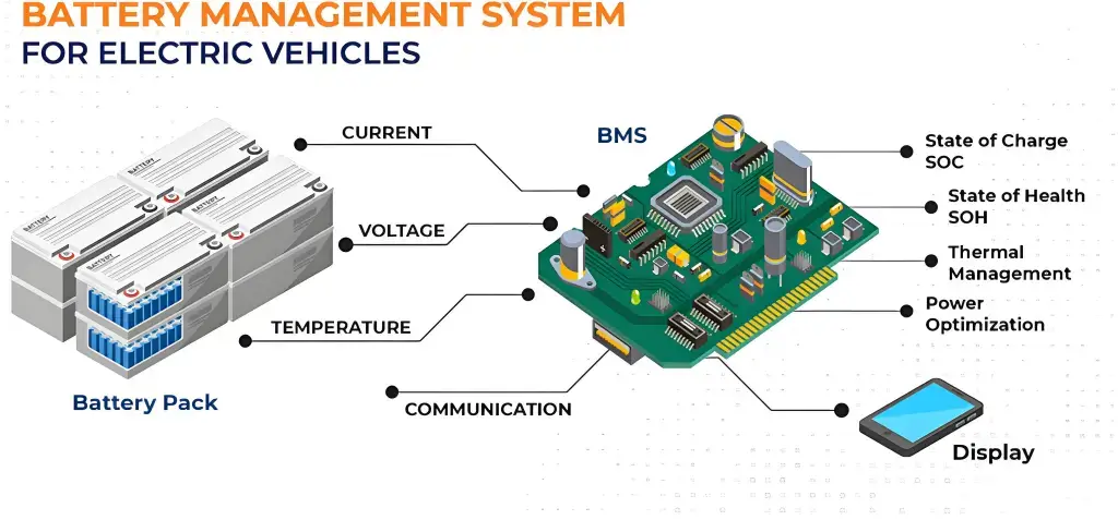
EV battery-management electronic boards perform functions including battery cell voltage sensing, battery cell balancing, battery cell protection switching, and battery pack communication. The 400 V / 800 V working voltage environment of this type of electronic board includes high- and low-voltage isolation zones, creepage and clearance, coating boundaries, connector retention, thermal paths that facilitate efficient operation of the board, and assembly procedures that maintain isolation between both high and low voltages while preserving traceability from the physical materials used to produce the board through to assembly. Balancing-resistor placement should maintain traceability and keep thermal drift from affecting low-voltage sense traces.
ADAS Radar and Camera PCB
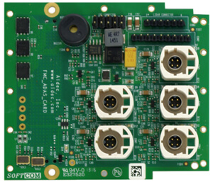
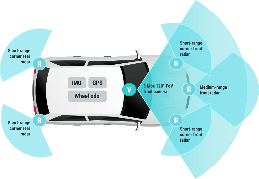
ADAS radar and camera PCBs combine RF or high-speed digital paths, image-processing packages, and dense connectors into one integrated package. The signal characteristics are determined by controlled impedance, RF material selection, high-density interconnect routing, shielding, and fine-pitch placement. X-ray, AOI, and functional tests identify various assembly risks before transitioning the design out of the prototype learning stage. A common failure mechanism on 77 GHz boards is crosstalk between the RF via fence and the adjacent digital escape route. While a design may pass controlled-impedance verification in isolation, once digital fanout is routed adjacent to the RF via fence, it may fail.
Engine and Powertrain Control PCB
Engine and powertrain controllers are subject to under-hood extreme temperature, vibration, power-device loading, and connector fatigue. High-temperature materials, strong solder-joint connections, the requirement for conformal coating, and lot traceability are more critical for these components than for most cabin-mounted modules. The placement of relays and drivers can impact both the thermal and mechanical loading on the assembly. The location of engine and powertrain controllers is generally aligned with AEC-Q100 Grade 0 (up to 150 °C). At this temperature range, solder-joint fatigue at the relay or connector interface, not at the relay or connector itself, is usually the first failure point during thermal cycling, which is why data related to joint inspection and thermal cycling is of greater importance than with cabin-mounted boards.
Infotainment and Connectivity PCB
Infotainment and connectivity PCBs include display interfaces, high-speed digital links, wireless modules, audio module interfaces, and dense board-to-board connectors. Impedance control, EMI management, fine-pitch visual inspection, connector durability, and functional coverage need to be addressed in the assembly process. High-speed links utilizing LVDS or MIPI technologies typically route controlled differential impedance in the 90-100 Ω range; connecting these links to board-to-board connectors within a few millimeters of each other without matching the transition is frequently the cause of intermittent display or camera-link malfunctions that only occur after the connectors are connected and subjected to vibration in the field.
Automotive Lighting PCB
Automotive lighting printed circuit boards support LED current, heat conduction, polarity, and exposure to moisture near optical components. The thermal path must be designed to ensure the board can conduct heat away from the components efficiently; in many cases, metal-core or thermal-via constructions are used for this purpose. The quality of solder joints, coatings, connector strain, and electrical test points will determine if an assembled PCB is capable of supporting the actual load it will be subjected to when it is used for lighting applications. For example, the LED forward voltage drops when the junction temperature of the LED increases; therefore, if a thermal path is marginally sufficient during bench testing, it can lead to thermal runaway for the LED string once it is sealed in a housing. Thus, the decision to use metal-core or thermal via must be validated at the enclosure level, not just on a bare printed circuit board.
Climate and Comfort Control PCB
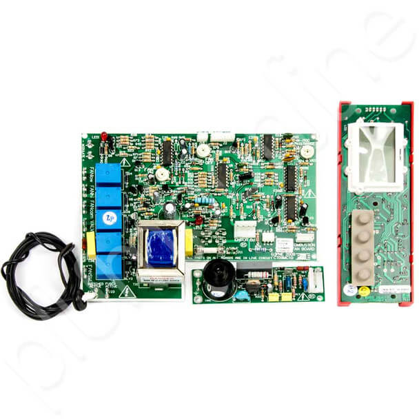
Climate and comfort-control printed circuit boards can comprise, among other things, motor drivers, relays, sensors, HMI inputs, and cabin-network interfaces. Assembly and testing plans must take into consideration conditions such as humidity, relay solder mass, connector wear, fan or actuator loads, firmware, and revision control. Motor-driver relays switching during a humidity cycle will fail faster than would be expected based solely on their pure current rating because condensation accumulates on the relay contact interface, causing accelerated surface degradation and associated failure modes.
Body Control and Door Electronics PCB
The body-control, door, window, mirror, seat, and keyless-entry PCBA includes motor drivers, sensors, relays, connectors, LIN or CAN communication, and other elements. Several variables exist in the assembly process that present practical assembly risk; some of these include humidity, vibration, connector strain, actuator current, and polarity. Repeated actuation cycles fatigue connector contacts through fretting corrosion long before the solder joint itself fails. As a result, many door-module test plans specify a separate cycle count on the connector interface for connector tests as opposed to electrical function tests.
Our Case
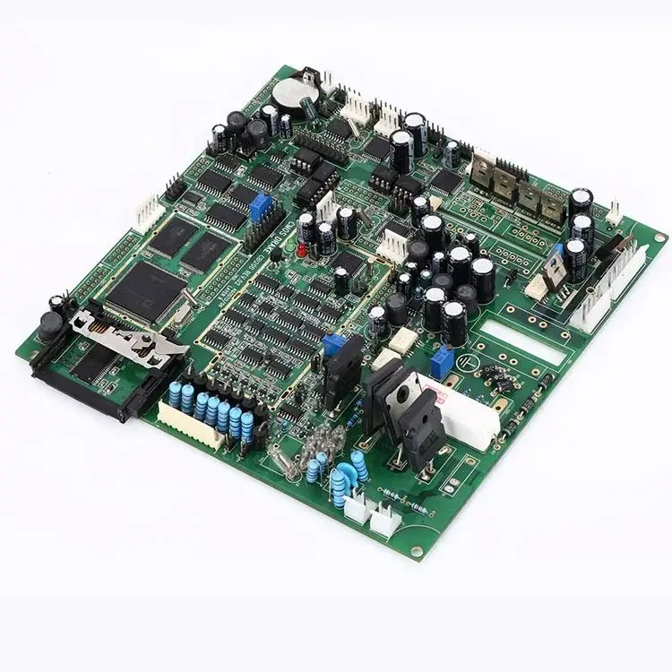
Examples of automotive PCB assembly illustrate how manufacturers use established starting points to create sound manufacturing processes. The examples in the following sections are anonymous examples of project assemblies; therefore, they should not be interpreted as claims about specific customers, yield improvements, or field performance for customer products.
EV BMS Assembly Pattern
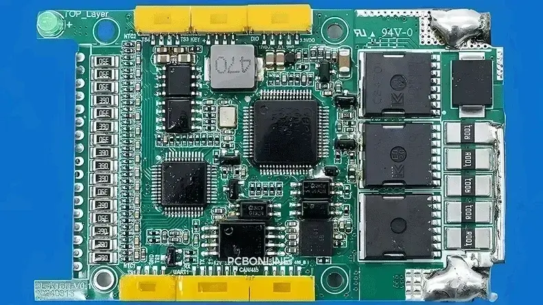
The BMS assembly pattern uses a six-layer BMS PCB with 3 oz thick copper. Its heat dissipation and electrical current path are the focus of the assembly design. Components that require soldering and inspection are affected by the thermal vias and embedded copper features.
ADAS Domain Controller Assembly
The ADAS domain controller pattern uses a 20-layer HDI domain controller with a BGA pitch of 0.3 mm. This assembly requires a coordinated approach to build-up, via, stencil application, and placement. In addition, inspection, impedance proof, and testing allow validation of whether this densely populated controller has been properly assembled and tested.
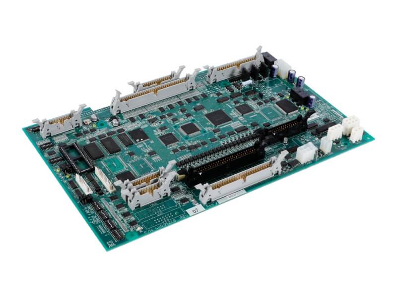
Engine Control Unit Assembly
One pattern of the ECU control board uses an eight-layer PCB that measures 1.8 mm thick, with a 3/3.5 mil line and space design, a minimum hole of 0.2 mm, hole-to-line spacing of 0.13 mm, outer copper of 1 oz, and immersion gold finish. The manufacturability and assembly-access checks will link to the lot and revision number.

Infotainment Display Assembly
The Infotainment Display assembly uses a 20-unit prototype that combines both SMT and THT and helps identify kitting, stencil-aperture, connector, and through-hole process issues before manufacturing. As a result, BOM verification and stencil optimization aid in providing additional information for determining potential process improvements. AOI, X-ray, or electrical checks at this prototype stage verify that the stencil and placement programs function properly on actual hardware; the results will not verify the long-term quality and consistency of solder paste or connectors until pilot-scale data is produced.
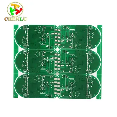
Automotive Lighting Control Assembly
An LED driver circuit board assembly includes thermal paths, polarity, connector types, and moisture limitations in addition to other factors affecting the selection of materials used to build the assembly, solder profiling, coating or masking techniques, and accessibility for test points. Current load, optical inspection or AOI, and functional inspections will support future changes to the lighting assembly itself.
Automotive PCB Failure Risks
When there are factors associated with the mission profile, mechanical loads, component density, or lack of component availability that create a situation where routine assembly controls are insufficient, additional review may be required during the automotive build.
Thermal and Environmental Stress
Automotive builds use PCBs that can be subjected to high temperature, heat produced by LEDs, high-current copper traces, components housed within sealed enclosures, or cyclic temperature change. Thermal and environmental stresses will impact the solder joints as well as the laminate; therefore, the entire assembly is reviewed based on both the mission profile and the means of dissipating the heat generated within the assembly.
The control decision may result in changes to the PCB design, the type of alloys or soldering processes utilized, the coating applied to the PCB, the method used to attach the components to the PCB, and the validation plan to ensure the integrity of the assembly.
Vibration and Mechanical Fatigue
Mechanical vibration and mechanical fatigue will place stresses on the solder joints and PCB due to heavy components, connectors, moving harnesses, and the enclosure transferring mechanical stress to the PCB. Therefore, any time an assembly lacks support structures located in close proximity to a connector, or if a connector is transferring vibration energy to the PCB, the risk associated with solder failure will be increased.
In addition, mechanical drawings, the current load limitations of the connectors, PCB support structures, fixtures used to secure the assemblies to the test equipment, and shock/vibration requirements should be collectively reviewed. Also, the results of inspections should be clearly marked with both the revision of the assembly that resulted in the inspection finding and the corrective action taken based on the inspection finding. The vibration station test should replicate the assembly as it would be expected to be installed and the actual circumstances in which it will be supported.
Density and Signal Integrity
The use of dense BGA packages and high-density interconnect structures, along with the use of high-speed links and RF paths, limits space for thermal relief features, inspection methods, test access opportunities, and rework options. Compact integration could solve an enclosure issue while creating an assembly or verification problem.
Your review should consider the stack-up, via strategy, package geometry, impedance plan, X-ray access, and the ability to test. In this case, you should verify the approved stack-up and the BGA data, as well as the inspection access and the interface or impedance limits used for testing.
Component Lifecycle and Traceability
An allocation, obsolescence, alternate part, date-code limit, or version change may all impact an approved build. The purchasing method you use may also change the electrical behavior, qualification status, thermal performance, and firmware compatibility of this build.
Your BOM should list approved parts as well as their approved alternates. Any substitution should follow the agreed-upon technical and customer approval process. The BOM approval, change history, lot record, and date show the materials used in each build. No alternate part should enter production based on availability alone.
From Automotive PCB Prototype to Production
Automotive PCB prototypes, pilot runs, and production of PCB assemblies all serve different purposes. Engineering clarification, validation, revision freeze, or approval for changes must not be replaced by speed during any of the assembly stages. Every stage should have specific inputs, outputs, and exit conditions to ensure that assembly knowledge carries over into the next stage.
Engineering Prototype
An engineering prototype is a learning build. It gives an opportunity to check assembly fit, material assumptions, component status, inspection access, programming, and selected functions. Preliminary files may be provided to initiate discussion, but a build must capture which assumptions remain to be validated.
Run timing depends on finished-part availability, BOM completeness, manufacturing complexity, test coverage, quantity, and expedite conditions. Any open questions, such as component substitutions, coatings that have not been tested, and test limits that have not been confirmed, must be resolved before the pilot run can commence.
Validation and Pilot Run
The pilot run tests production-intent materials, tooling, inspection, and final test. Before manufacturing the pilot run, all of the prototype test results should have been closed or assigned, and the purpose and acceptance criteria for the sample must be fully defined. A process-learning lot, design-validation sample, and customer submission are not to be treated similarly.
The exit requirement for the pilot run is to validate that the process for manufacturing can be successfully repeated at pilot scale. This information will be documented, such as issue closure, inspection and test results, tooling that is in good condition, and any process changes.
Production-Intent Release
Once a product has been released for production, the approved asset set, BOM and any alternate BOMs, assembly instructions, and revision information will be locked down for production. The asset released for production must be fully reproducible.
The clean release sets the approvals required for changes made after the release. Linking the data for fabricating the product to the BOM, centroid, drawings for the product, firmware, and test specifications will prevent conflicting revisions. No production should start from a folder of similar files.
Production Ramp and Change Control
During the ramp-up production, monitor output, capacity, and approved changes. If a facility has a capacity of 20,000 m² and there are a maximum of 60 million SMT solder joints manufactured each month, there still needs to be an actual production plan, allocation of lines, inspection and test procedures, and support of forecast production.
Any changes made to the material, process, tooling, documents, or firmware will follow the process and method of approval already established. All revision-linked records during production ramp-up will create a record of history and a usable record of the capacity growth rate.
How Do You Compare Automotive PCB Assembly Suppliers?
To analyse an automotive PCBA supplier, evaluate the quality management system, how the design process relates to its manufacturing process, coverage of inspection and testing, how traceable the product will be, what type of support it receives during different stages of manufacturing, and the response to change control. All certification, alignment to design and process, inspection and test coverage, traceability, production-stage support, and controlled changes must flow through the actual site and process plans where all manufacturing occurs.
| Evaluation area | Weak signal | Stronger proof | Next action |
|---|---|---|---|
| Quality-system coverage | Logo or unsupported certification statement | Current certificate coverage and relevant site/process proof | Confirm applicability to the planned production lot |
| Design-to-Process Alignment | Long capability list | Review tied to stack-up, BOM, packages, soldering and test needs | Request written assumptions and open issues |
| Test and traceability | Equipment names | Defined coverage, result format and product/lot link | Review a redacted example |
| Prototype and production support | “Fast” or “scalable” | Stage outputs, capacity context and controlled transfer | Agree stage exit criteria |
| Revision and change control | Price without technical context | Revision-aligned commercial response, exclusions, alternates and approval method | Compare on the same confirmed manufacturing information |
Which Quality System Covers the Production Site?
Verify which legal entity owns the certificate for the site, what processes are covered, and whether the proposed build uses that site. Also check the revision and status of the certification, and note that you cannot confirm that a particular site is applicable to your products just by seeing the logo on a website.
The methods of planning in the project still need to be used within a certified system. Determine which applicable APQP, PPAP-related, control plan, traceability, and change records apply to the program.
Can the Process Match the Board Technology?
A supplier response should tie together the actual stack-up, BOM, package types, soldering used, coatings used, programming done, inspections, and testing required. The response will also raise open questions and detail the known assumptions in writing.
A long list of capabilities alone is less conclusive proof. Ask what happens if the copper, material, BGA geometry, connector load, or test points change. The answer to that question will let you know if your supplier is looking at the project or if they are just trying to match a set of keywords.
How Are Test Results Linked to Each Lot?
When evaluating supplier performance, be sure to look at the equipment name and the defects and functions covered by each supplier. Be sure to ask which parts will be inspected, how they will be inspected, what limits will be put on each part, what will happen to parts that fail, and how the results of testing will link to each part, lot, and revision.
Using a redacted results format may expose gaps before the order is placed. Quality Assurance teams can assess whether the historical record for each lot will support incoming verification, customer submission, or future failure investigation.
Can Prototype Controls Scale to Production?
Compare stage outputs, material transfer, capacity allocation, ramp control, and prototype development. A fast prototype's value is limited if its material, tooling, and test process are not sufficient for the later project stages.
The claim "30 years of experience" is not enough context. You should request an audit report from the project site or a customer reference from a similar automotive project, in addition to documents proving that the site, team, automotive project type, and manufacturing plan are verifiably the same.
How Are Revisions and Changes Approved?
A revision control procedure must identify the manufacturing documentation being used for the manufacture of the part, all approved alternates and controlled processes, and who has been authorized to approve any changes made.
A response must also state how the supplier's material, process, documentation, firmware, and testing changes are proposed and approved. A quick pricing response without having these items documented will obscure these items until after the product has been released.
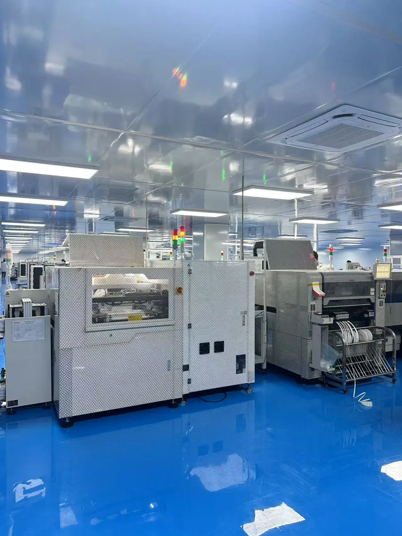
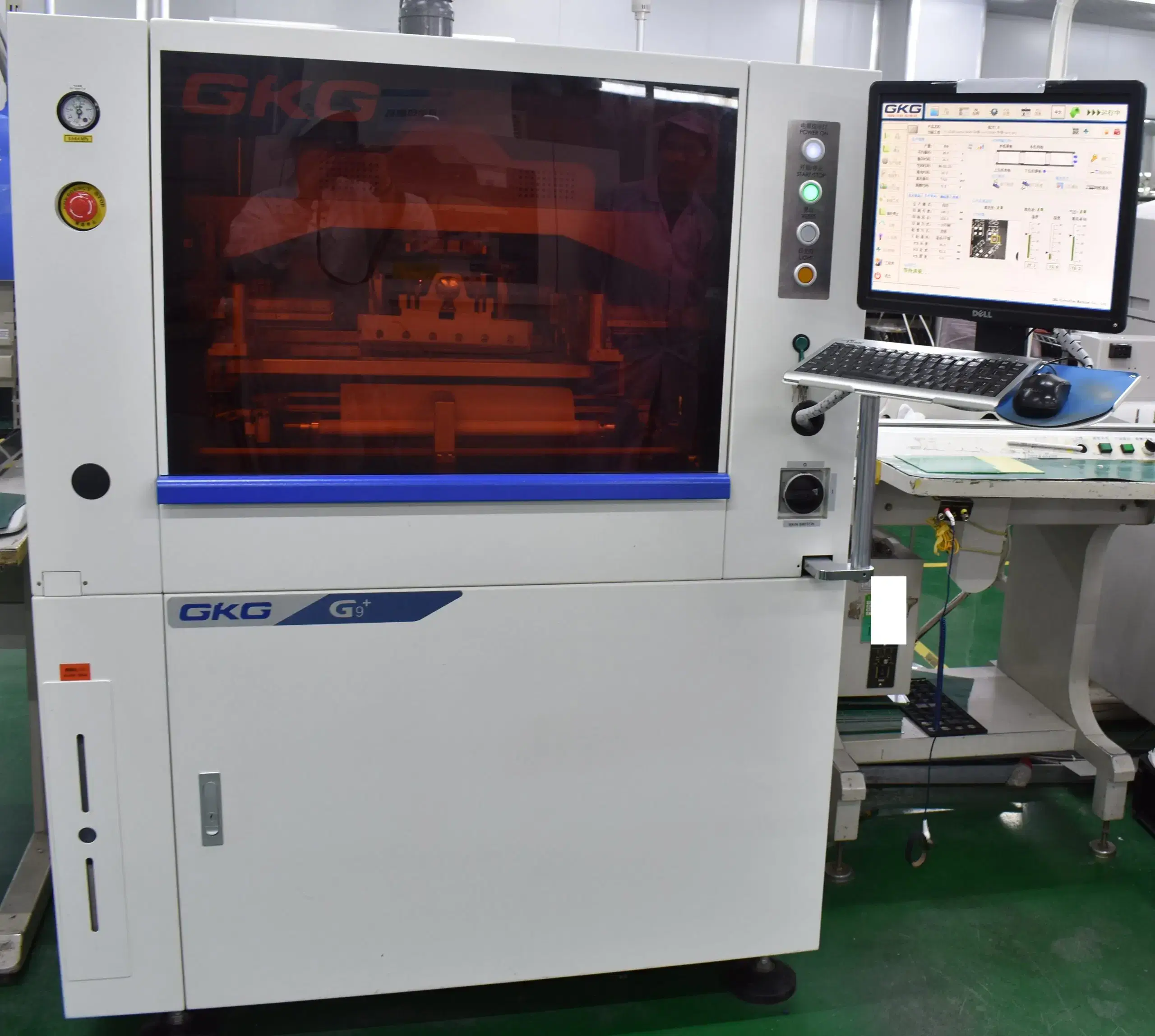
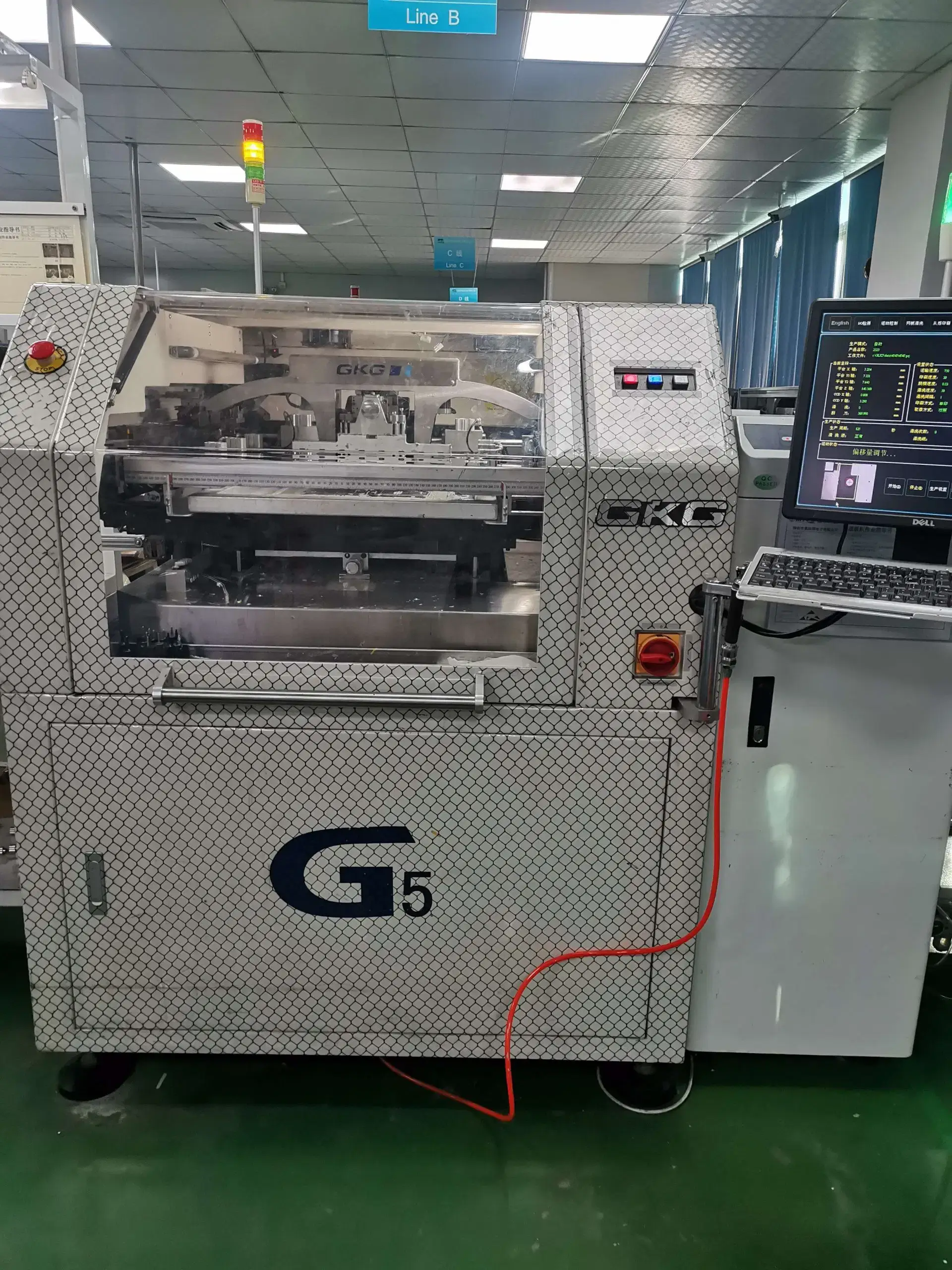
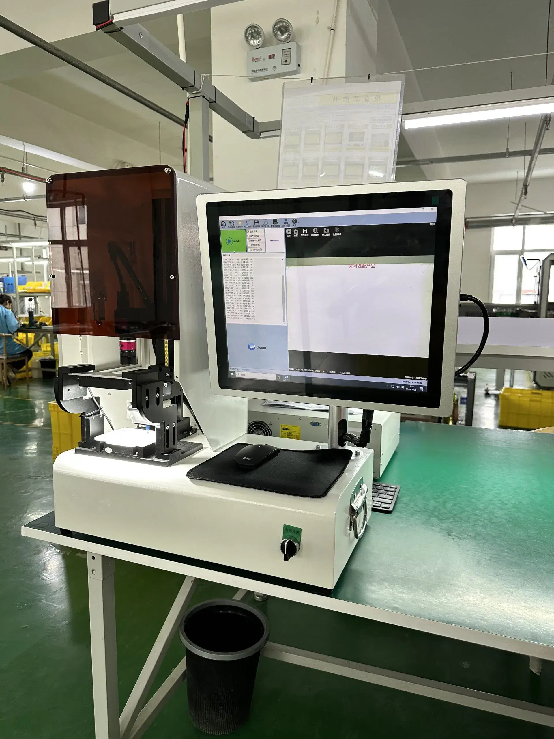
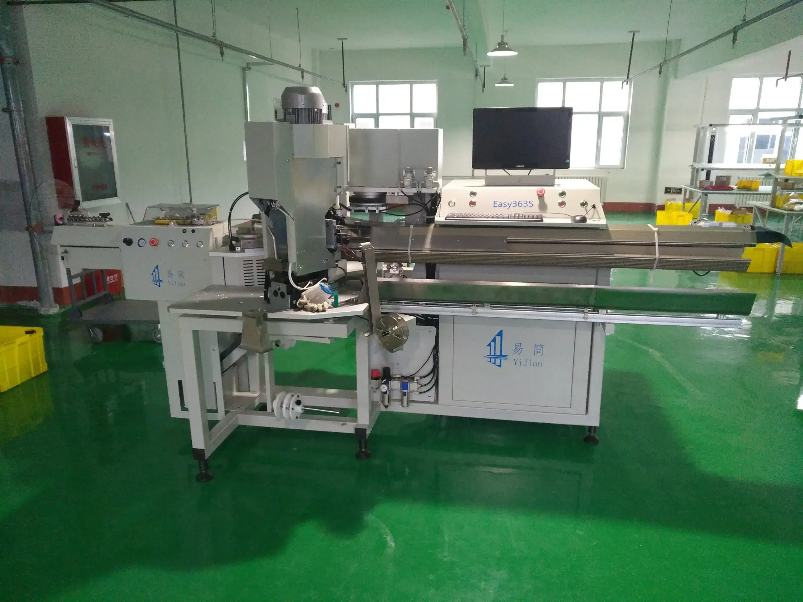
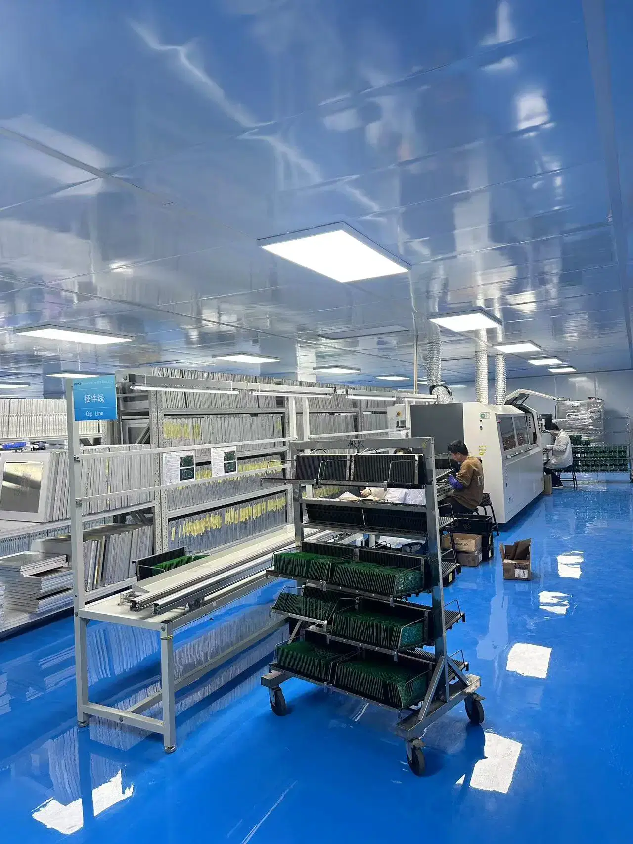
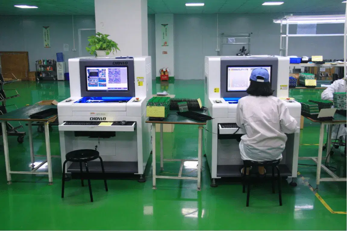
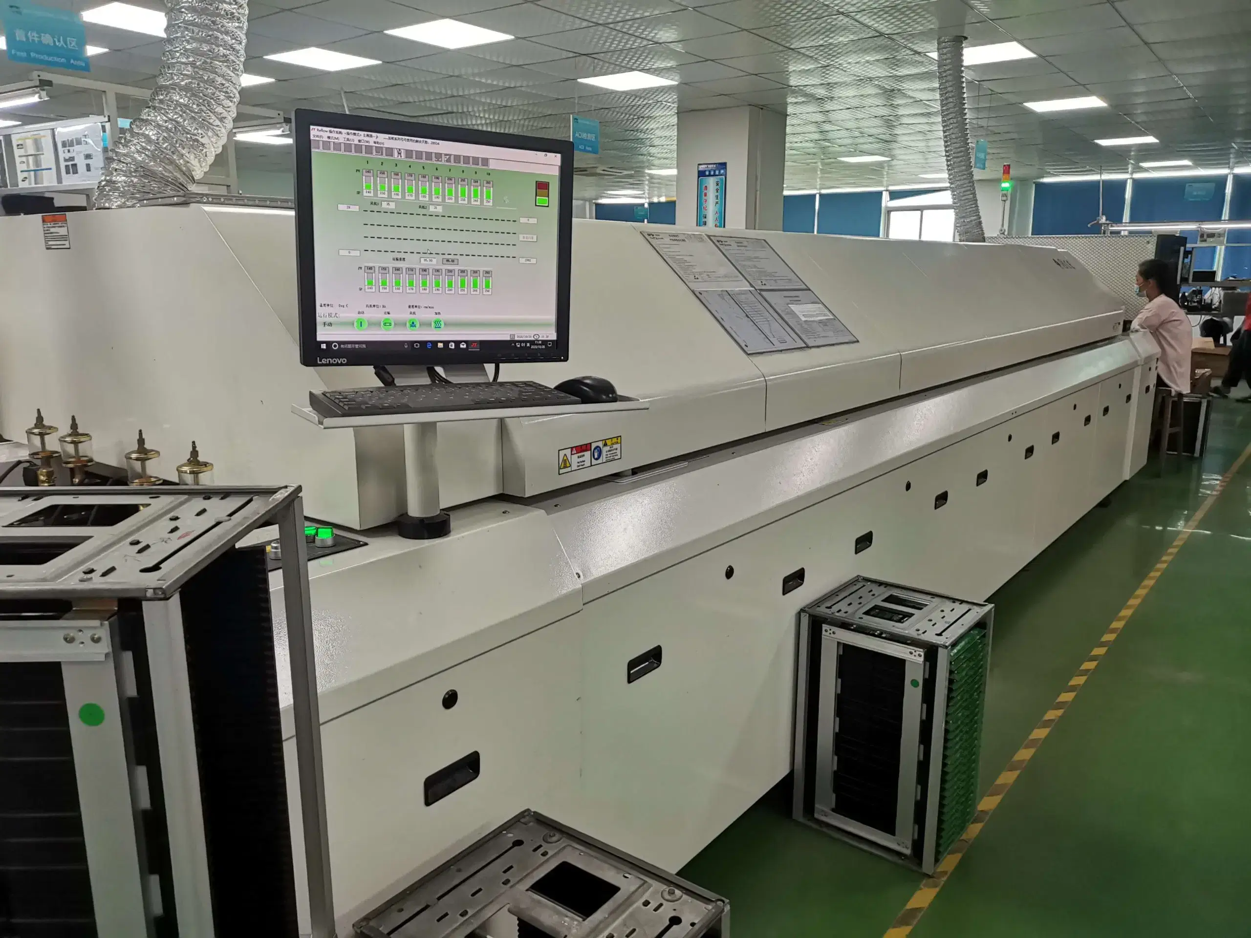
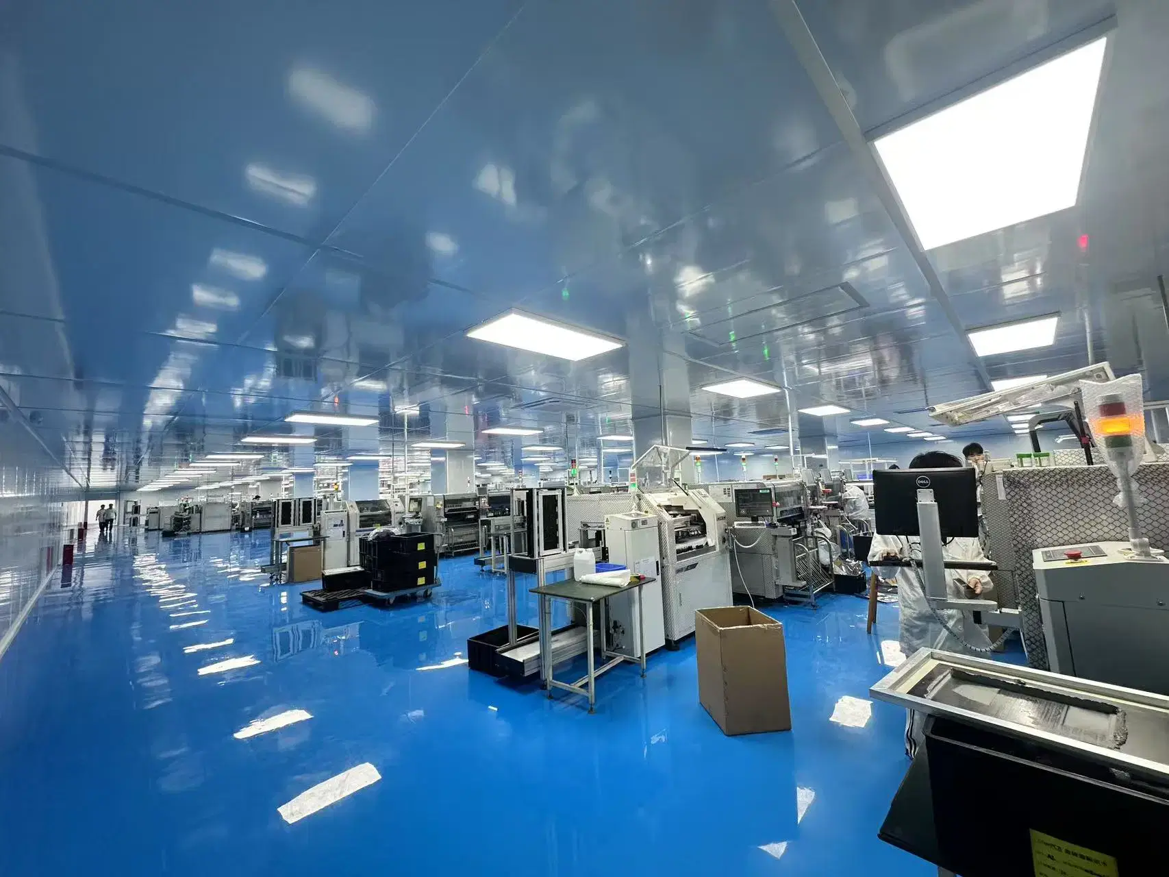
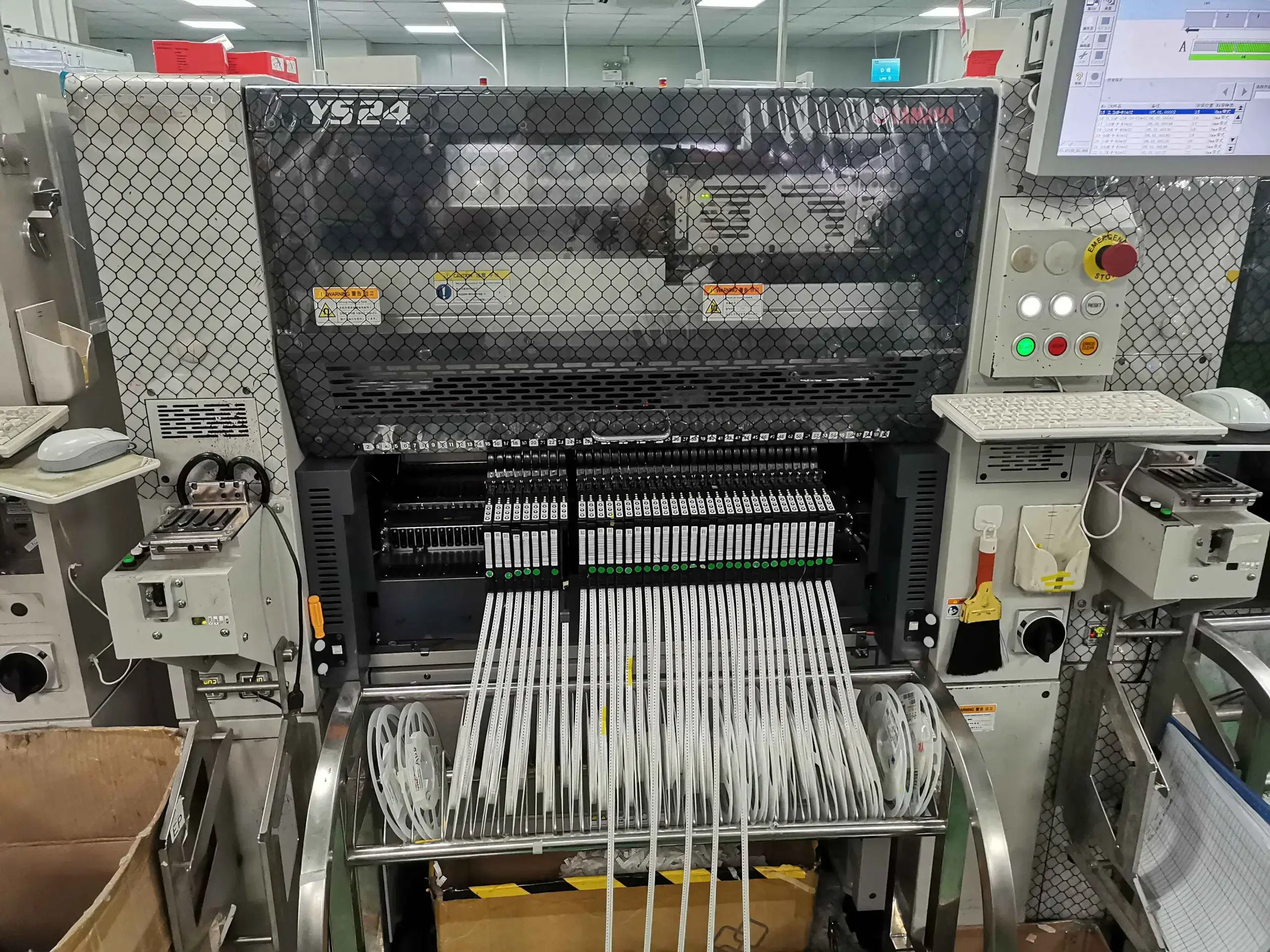
Our PCB Factory Gallery
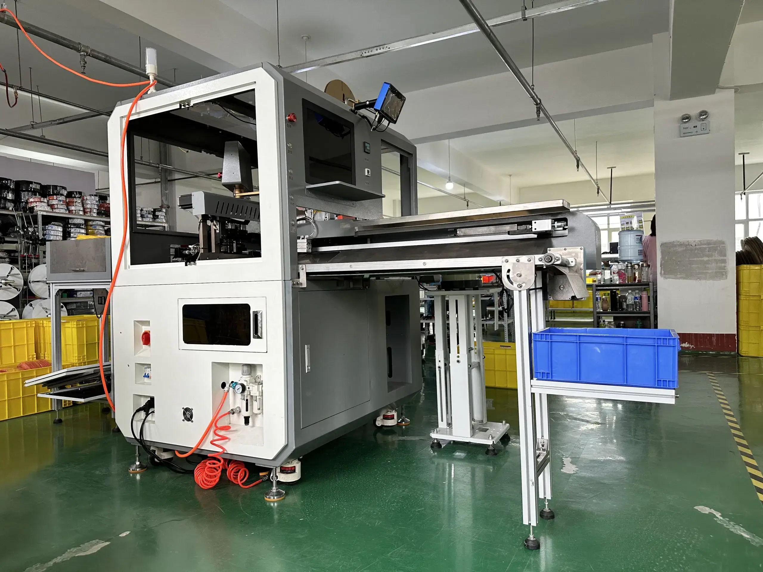
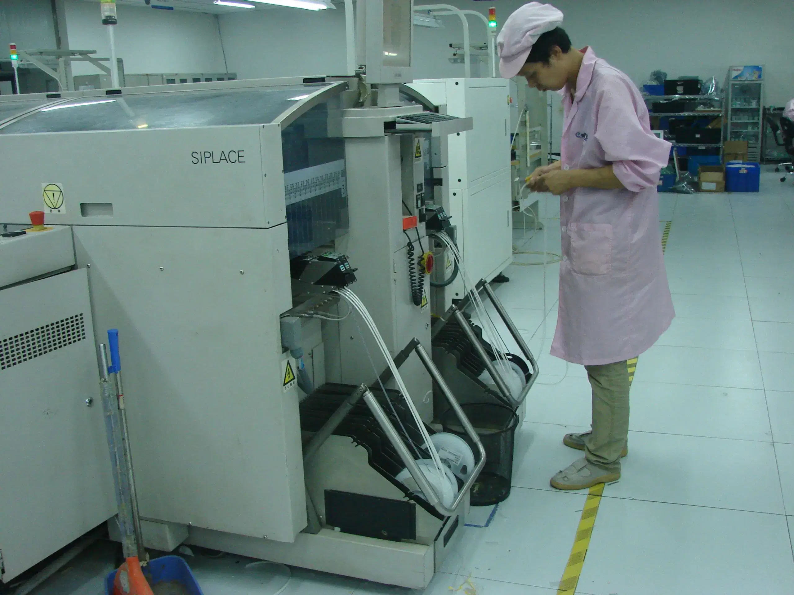
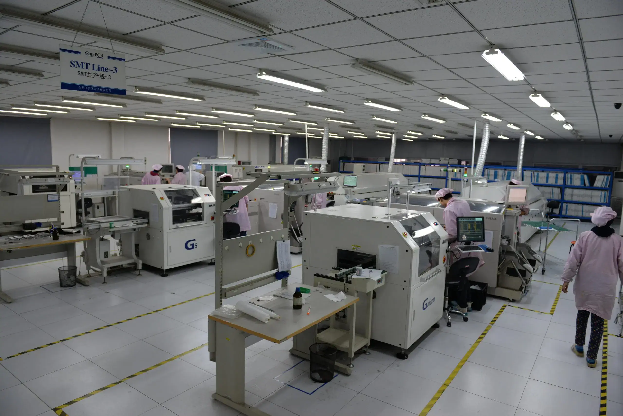
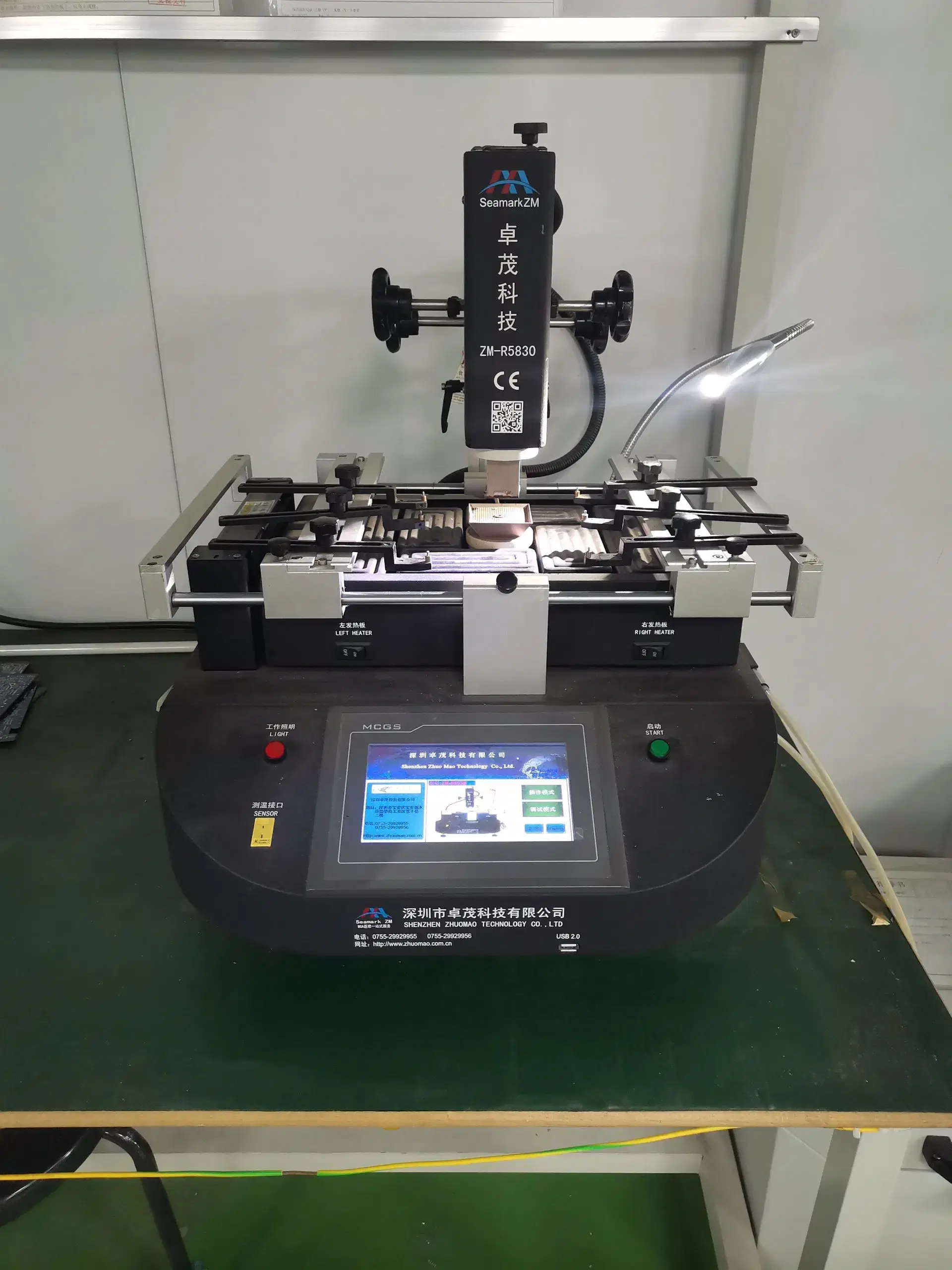
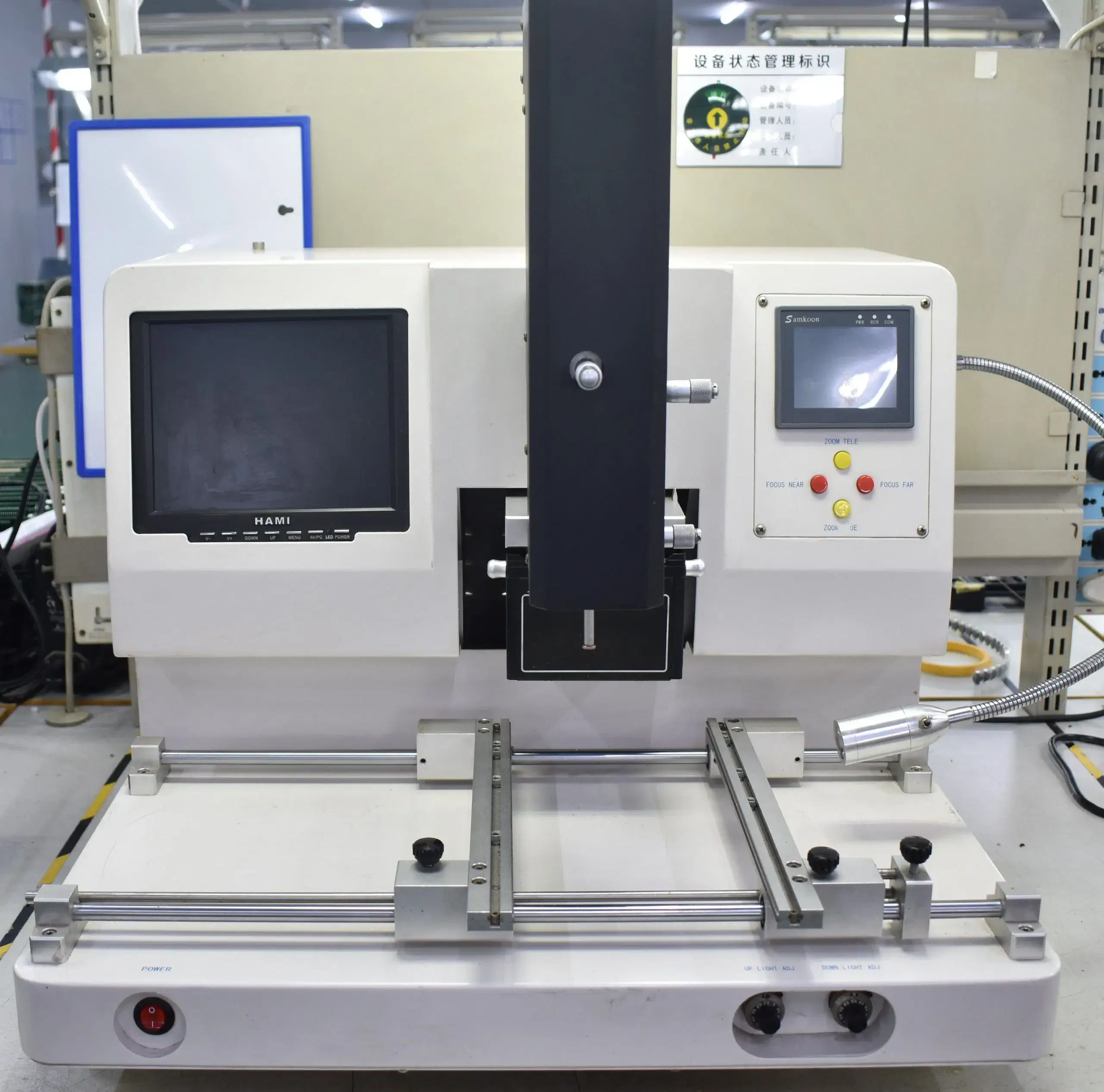
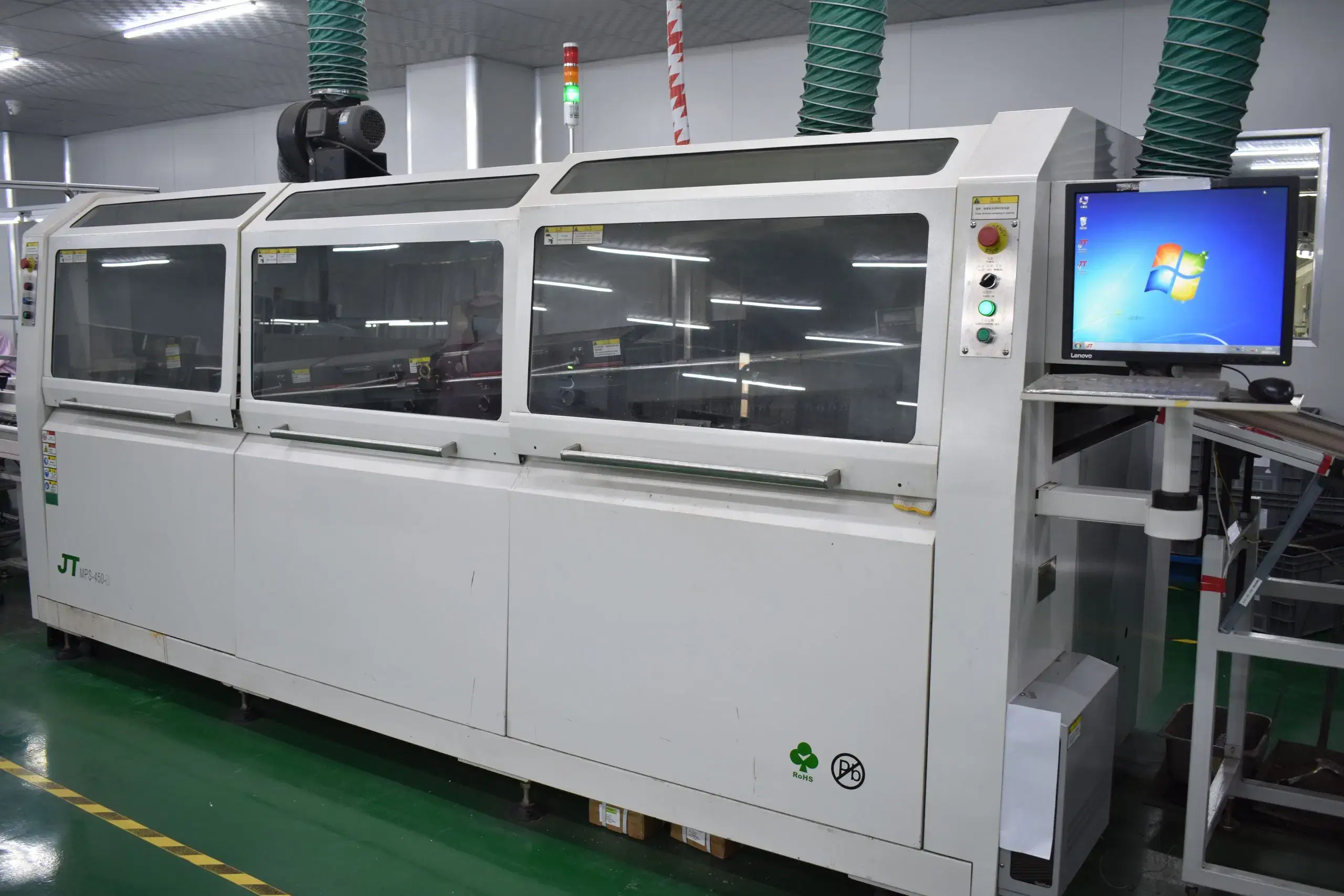
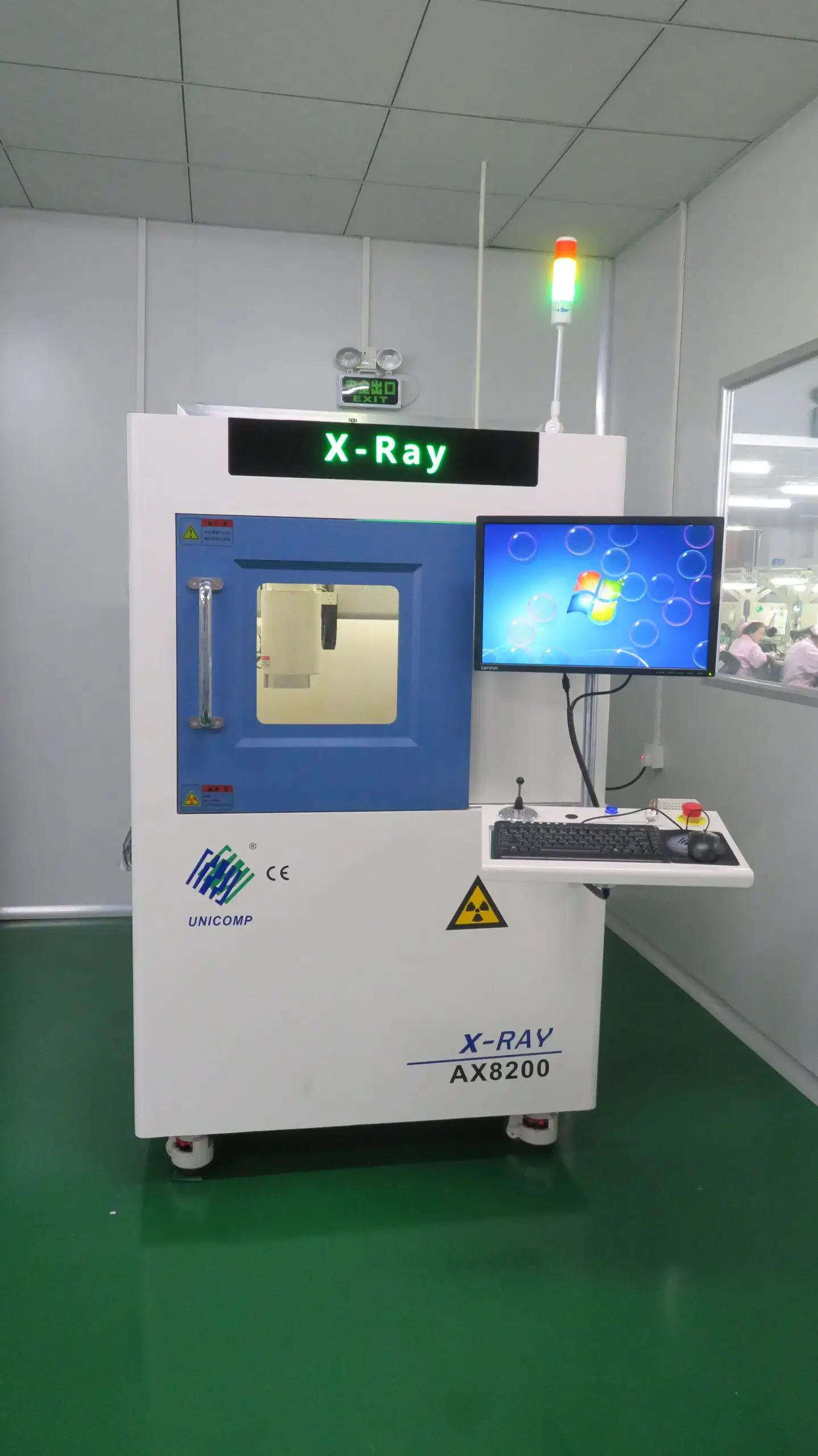
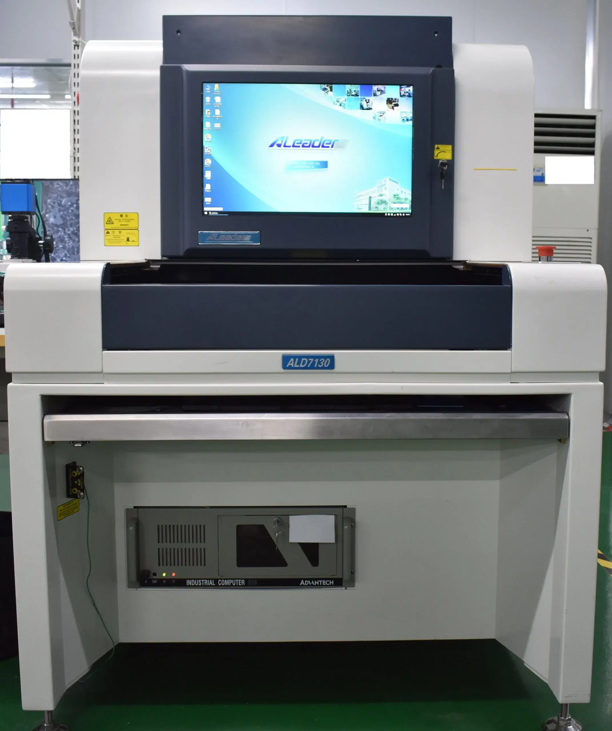
Frequently Asked Questions
Dimensional tolerance begins by monitoring materials as they are moved; using bend-zone geometry, datum strategy, panel design, and assembly tooling allows finished measurements to follow the drawings and qualified process capability for rigid-flex or flex construction.
Manufacturing information received from the customer will be the major determining factor on lead time; however, laminate and component availability, board construction, assembly process, test coverage, the number of lots produced, and the current stage of production all need to be considered separately when establishing a lead-time schedule.
Yes. Prototypes are used for engineering learning, assembly verification, and functional testing before the full qualification of the PCB assembly. An AEC-qualified component does not qualify the complete PCBA, and a prototype does not supplant the PPAP or production approval requirement.
The primary differences will typically be in four areas: temperature grade (AEC-Q100 Grade 0-3 as compared to the single rating of the consumer part), evidence of process capability (Cpk ≥1.67 initial / ≥1.33 ongoing vs. no formal capability requirement), granularity of traceability (lot, panel, or serialized unit vs. batch level), and change approvals (documented PPAP-linked vs. informal). A board could have all these controls but still fail if the underlying materials and processes do not meet the requirements of the mission profile; therefore, the label does not demonstrate anything.
There are three concrete advantages to using a properly specified automotive PCB. First, there will be fewer field failures, which can be traced back to thermal or vibration fatigue because validation of the construction was performed against the actual mission profile; secondly, root-cause analysis will be faster in the event of any failure due to lot-level or serialized traceability linking the failed unit back to material and process documentation; and thirdly, requalification costs are lower when an automotive PCB's component reaches its end of life because the approved alternate list and change-control procedures were established before the shortage, rather than after it occurred.